EP0280467A1 - Procédé de fabrication de soupapes à microstructure variable - Google Patents
Procédé de fabrication de soupapes à microstructure variable Download PDFInfo
- Publication number
- EP0280467A1 EP0280467A1 EP88301366A EP88301366A EP0280467A1 EP 0280467 A1 EP0280467 A1 EP 0280467A1 EP 88301366 A EP88301366 A EP 88301366A EP 88301366 A EP88301366 A EP 88301366A EP 0280467 A1 EP0280467 A1 EP 0280467A1
- Authority
- EP
- European Patent Office
- Prior art keywords
- temperature
- grain size
- valve
- head portion
- slug
- Prior art date
- Legal status (The legal status is an assumption and is not a legal conclusion. Google has not performed a legal analysis and makes no representation as to the accuracy of the status listed.)
- Ceased
Links
Images


Classifications
-
- C—CHEMISTRY; METALLURGY
- C21—METALLURGY OF IRON
- C21D—MODIFYING THE PHYSICAL STRUCTURE OF FERROUS METALS; GENERAL DEVICES FOR HEAT TREATMENT OF FERROUS OR NON-FERROUS METALS OR ALLOYS; MAKING METAL MALLEABLE, e.g. BY DECARBURISATION OR TEMPERING
- C21D8/00—Modifying the physical properties of ferrous metals or ferrous alloys by deformation combined with, or followed by, heat treatment
-
- B—PERFORMING OPERATIONS; TRANSPORTING
- B21—MECHANICAL METAL-WORKING WITHOUT ESSENTIALLY REMOVING MATERIAL; PUNCHING METAL
- B21K—MAKING FORGED OR PRESSED METAL PRODUCTS, e.g. HORSE-SHOES, RIVETS, BOLTS OR WHEELS
- B21K1/00—Making machine elements
- B21K1/20—Making machine elements valve parts
- B21K1/22—Making machine elements valve parts poppet valves, e.g. for internal-combustion engines
-
- F—MECHANICAL ENGINEERING; LIGHTING; HEATING; WEAPONS; BLASTING
- F01—MACHINES OR ENGINES IN GENERAL; ENGINE PLANTS IN GENERAL; STEAM ENGINES
- F01L—CYCLICALLY OPERATING VALVES FOR MACHINES OR ENGINES
- F01L3/00—Lift-valve, i.e. cut-off apparatus with closure members having at least a component of their opening and closing motion perpendicular to the closing faces; Parts or accessories thereof
- F01L3/02—Selecting particular materials for valve-members or valve-seats; Valve-members or valve-seats composed of two or more materials
-
- F—MECHANICAL ENGINEERING; LIGHTING; HEATING; WEAPONS; BLASTING
- F01—MACHINES OR ENGINES IN GENERAL; ENGINE PLANTS IN GENERAL; STEAM ENGINES
- F01L—CYCLICALLY OPERATING VALVES FOR MACHINES OR ENGINES
- F01L2303/00—Manufacturing of components used in valve arrangements
-
- Y—GENERAL TAGGING OF NEW TECHNOLOGICAL DEVELOPMENTS; GENERAL TAGGING OF CROSS-SECTIONAL TECHNOLOGIES SPANNING OVER SEVERAL SECTIONS OF THE IPC; TECHNICAL SUBJECTS COVERED BY FORMER USPC CROSS-REFERENCE ART COLLECTIONS [XRACs] AND DIGESTS
- Y10—TECHNICAL SUBJECTS COVERED BY FORMER USPC
- Y10T—TECHNICAL SUBJECTS COVERED BY FORMER US CLASSIFICATION
- Y10T29/00—Metal working
- Y10T29/49—Method of mechanical manufacture
- Y10T29/49229—Prime mover or fluid pump making
- Y10T29/49298—Poppet or I.C. engine valve or valve seat making
- Y10T29/49306—Valve seat making
Definitions
- This invention relates generally to a process for controlling microstructure of a value member and more particularly to a process for providing the head and stem portions of an engine valve member with different microstructure grain sizes and harnesses advantageously tailored for engine applications.
- Valve members for use in internal combustion engines, particularly diesel engines, are expected to perform for long periods of time under rigorous conditions.
- the head portion including the seat face and the combustion face of the valve member exposed to the combustion chamber, is required to resist a variety of factors including high temperature, high pressure, corrosion, fatigue, erosion and wear while the stem portion of the valve member is required to possess high strength, wear and fatigue characteristics at temperatures lower than the temperature to which the head portion combustion face is exposed.
- the aforementioned method relies upon selective solution heat treatment to enlarge the grain size only in the head portion requiring expensive apparatus to shield the stem portion from the solution head treating temperature whereas the present invention is operative to use less expensive more conventional equipment to provide the microstructure grain size characteristics desired as well as providing the seat face of the head portion with improved resistance to wear.
- the process of the invention is applicable to any metallic valve material that is suitable for the particular application involved and which is forgeable and possesses a microstructure that responds to solution heat treating.
- metallic valve material include the Austenitic steels of the S.A.E. EV series such as 21-2N; 21-4N; and 23-8N and similar compositions.
- the invention is also applicable to solution heat treatable steels of the S.A.E. HEV series, nickel base alloys such as those sold under the trade designations Inconel, Waspalloy, Nimonic and similar compositions all of which are hereinafter described generally as "metallic valve" compositions.
- FIGURE 1 Nomenclature commonly used to identify various locations on an engine valve is shown in FIGURE 1 in which the head portion includes: a "combustion face” that faces inwardly into the engine combustion chamber; a “seat face” which is likewise located in but faces away from the combustion chamber and is the peripheral surface about the head portion that engages the engine block or insert if such is included; and the "fillet” which commonly tapers concavely inwardly to join the head with the "stem” of the valve at the "stem - fillet blend” which is often extended into a longer stem which is a “friction” or “resistance welded thereto” and ends in a “tip” adjacent to which a "keeper groove” is commonly included for connecting the valve to an engine member operative to reciprocate the valve synchronously with the engine combustion sequence.
- a "combustion face” that faces inwardly into the engine combustion chamber
- a “seat face” which is likewise located in but faces away from the combustion chamber and is the peripheral surface
- valve stem is extended, it is the upper stem of FIGURE 1 that is provided by the process of the invention.
- the head and stem portions are generally cylindrical with the head portion having a diameter substantially greater than the stem portion.
- final diameter does not necessarily means “finished diameter” since subsequent machining may be employed to provide the finished diameter subsequent to making the valve by the process of the invention.
- FIGURE 2 The effect upon microstructure and hardness at various locations on a valve member 2 made from the compositions of Table I by the process of the invention is shown in FIGURE 2 for which the initial average A.S.T.M. grain size of slug 4 of FIGURE 3 was about 2-3 distributed substantially uniformly throughout.
- the process of the invention provides a valve made from the composition of Table I having: a generally uniformly equiaxed grain size of 2-3 and an ambient hardness of 28-36 Rc in the head portion beneath the combustion face; large elongated grains surrounded by smaller grains providing an A.S.T.M. grain size of 2-9 and an ambient hardness of 40-47 Rc at the seat face; a minority of elongated grains having an A.S.T.M. grain size of about 2 surrounded by smaller equiaxed grains having an A.S.T.M. grain size 6-8 and an ambient hardness of 31-37 Rc at the fillet; and small equiaxed grains in the stem portion having an A.S.T.M. grain size of 6-8 distributed substantially uniformly throughout the stem portion providing an ambient hardness of 30-34 Rc.
- the process of the invention hereinafter described also enables eliminating the problem of pitting on the valve head combustion face arising from carbonitride stringers commonly associated with valves made for example from 21-2N material having the composition shown in following Table II and illustrated in FIGURE 4 where combustion face 20 of a valve head having a seat face 22 and a fillet portion 24 includes pitting 28 arising from carbonitride stringers 26.
- composition of Table II includes carbon and nitrogen which characteristically promotes formation of carbonitride stringers in valves made by conventional prior art processes.
- Such stringers are commonly found in austenitic steel engine valves and lead to the pitting on the combustion face previously described for FIGURE 4.
- the face pitting may arise from tearing at the combustion face during forging or by entrapped forging lubricant forced between the carbonitride stringers and the metal matrix and which can be further enlarged by preferential oxidation during subsequent heat treating of the forged valve.
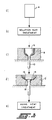
- FIGURE 3 enables economic production of valves made from commonly used metallic valve compositions having a coarse grain size of from about A.S.T.M. 1 to about 7 in the central region of the head portion beneath combustion face providing optimum high temperature fatigue and creep properties; a heavily cold worked grain structure at the valve seat providing optimum hot hardness and moderate to high temperature wear resistance; and a fine grain size of less than about A.S.T.M. 7 in the stem portion providing optimum moderate to low temperature fatigue, impact, and wear properties.
- the process of the invention further includes a step of heat aging subsequent to the forging of step (3) at a temperature and for a time and at a temperature predetermined to optimize hardness and strength and hardness for the grains associated with the head and stem portions.
- step (3) is preferably done in two steps shown as forge extrusion step (c) and forge upset step (d) in FIGURE 3 after which is preferably included the above described heat aging step.
- the reduction ratio between the slug and forge extrusion step (c) is about 3 to 1 and between forge extrusion step (c) and forge upset step (d) about 1.8 to 1.
- step (c) the solution heat treated slug 4 of step (b) is forged at a predetermined temperature in a first die 8 that is adapted to partially form the head portion of the valve but of smaller head diameter and only partially forming fillet portion 18 and seat face 16 whilst extruding the stem portion 10 therefrom in substantially its final form and thence in step (d) forging the partially forged product of step (c) in die 12 at a predetermined reduced temperature from the temperature of step (c) to decrease the diameter of head portion 14 to that desired whilst completing fillet portion 18 and seat face 16 and in particular cold working seat face 16 to provide the optimum properties thereat previously described.
- step (b) for super alloys such as Nimonic 80A is done at a temperature of from about 1800°F to about 2300°F for about 1 hour for metallic valve compositions at the low end of the temperature spectrum and for as little as one minute for those at the high end of the temperature spectrum.
- solution heat treating is preferably done at a temperature of from about 2100°F to about 2300°F for a period sufficient to dissolve the stringers.
- step (b) For valve compositions such as 21-2N previously described, it has been found solution heat treating in step (b) between 1900°F and 2125°F for a minimum of 30 minutes is highly effective in spherodizing the carbonitride stringers which greatly reduces combustion face pitting.
- the solution heat treating step can be conducted by heating the valve composition in either a suitable gaseous or liquid medium by conductive, inductive, radiative or other heating means well known to those skilled in the art of solution heat treating metallic compositions.
- the heat aging step after forging is preferably conducted in air for compositions such as 21-2N previously described at a temperature of about 1350°F to about 1550°F for about 10 to about 16 hours and for valve compositions such as Nimonic 80A in two steps as hereinafter described.
- valve made of Nimonic 80A shown in FIGURE 2 having the composition shown in Table I was made by the process of the invention by providing the wrought cylindrical slug of step (a) by slicing a wrought cylinder and then:
- the product of step (b) is air cooled to the temperature required for forge extrusion step (c) and cooled in vermiculite after step (d) to the air aging temperature described for step (e) and may also be air cooled after step (c) if desired.
Landscapes
- Engineering & Computer Science (AREA)
- Chemical & Material Sciences (AREA)
- Mechanical Engineering (AREA)
- Combustion & Propulsion (AREA)
- General Engineering & Computer Science (AREA)
- Physics & Mathematics (AREA)
- Thermal Sciences (AREA)
- Crystallography & Structural Chemistry (AREA)
- Materials Engineering (AREA)
- Metallurgy (AREA)
- Organic Chemistry (AREA)
- Forging (AREA)
Applications Claiming Priority (2)
| Application Number | Priority Date | Filing Date | Title |
|---|---|---|---|
| US07/017,293 US4741080A (en) | 1987-02-20 | 1987-02-20 | Process for providing valve members having varied microstructure |
| US17293 | 1987-02-20 |
Publications (1)
| Publication Number | Publication Date |
|---|---|
| EP0280467A1 true EP0280467A1 (fr) | 1988-08-31 |
Family
ID=21781802
Family Applications (1)
| Application Number | Title | Priority Date | Filing Date |
|---|---|---|---|
| EP88301366A Ceased EP0280467A1 (fr) | 1987-02-20 | 1988-02-18 | Procédé de fabrication de soupapes à microstructure variable |
Country Status (3)
| Country | Link |
|---|---|
| US (1) | US4741080A (fr) |
| EP (1) | EP0280467A1 (fr) |
| BR (1) | BR8800605A (fr) |
Cited By (4)
| Publication number | Priority date | Publication date | Assignee | Title |
|---|---|---|---|---|
| EP0526174A1 (fr) * | 1991-07-31 | 1993-02-03 | Trw Inc. | Procédé de fabrication d'une soupape d'échappement |
| WO1997047861A1 (fr) * | 1996-06-07 | 1997-12-18 | Man B & W Diesel A/S | Soupape d'echappement destinee a un moteur a combustion interne |
| EP1094202A3 (fr) * | 1999-10-20 | 2002-08-14 | Fuji Oozx Inc. | Procédé de durcissement d'une tete de soupape |
| EP2949766A1 (fr) * | 2014-05-21 | 2015-12-02 | Mahle International GmbH | Procédé destiné à la fabrication d'une soupape pour un moteur à combustion interne |
Families Citing this family (15)
| Publication number | Priority date | Publication date | Assignee | Title |
|---|---|---|---|---|
| DE3704948A1 (de) * | 1987-02-17 | 1988-08-25 | Sempell Armaturen Gmbh | Verfahren und vorrichtung zur herstellung eines tellerventilkopfes |
| DE3929534A1 (de) * | 1989-09-06 | 1991-03-28 | Daimler Benz Ag | Verfahren zur herstellung eines ventils |
| JPH0771717B2 (ja) * | 1990-03-26 | 1995-08-02 | 本田技研工業株式会社 | エンジンバルブの製造方法 |
| US5419791A (en) * | 1993-07-21 | 1995-05-30 | Folmer; Carroll W. | Method of heat assisted sheet metal forming in 360 degree shapes |
| JPH10219377A (ja) * | 1997-02-07 | 1998-08-18 | Daido Steel Co Ltd | ディーゼルエンジンの高耐食性吸排気バルブ用合金及び吸排気バルブの製造方法 |
| DE19705850C2 (de) * | 1997-02-15 | 2000-06-08 | Daimlerchrysler Aerospace Ag | Kryoventil |
| JPH1122427A (ja) * | 1997-07-03 | 1999-01-26 | Daido Steel Co Ltd | ディーゼルエンジンバルブの製造方法 |
| US6385847B1 (en) | 2000-09-13 | 2002-05-14 | Eaton Corporation | Seat faced engine valves and method of making seat faced engine valves |
| CN101305168B (zh) * | 2005-11-15 | 2010-05-12 | 日锻汽门株式会社 | 装入制冷剂空心提升阀及其制造方法 |
| FR2896514B1 (fr) * | 2006-01-26 | 2008-05-30 | Aubert & Duval Soc Par Actions | Acier martensitique inoxydable et procede de fabrication d'une piece en cet acier, telle qu'une soupape. |
| KR102285017B1 (ko) | 2018-03-20 | 2021-08-04 | 니탄 밸브 가부시키가이샤 | 배기용 중공 포핏 밸브 |
| CN112752895B (zh) | 2018-11-12 | 2023-10-13 | 日锻株式会社 | 发动机的提升阀的制造方法 |
| JP7329201B2 (ja) | 2020-03-30 | 2023-08-18 | 株式会社Nittan | エンジンのポペットバルブの製造方法 |
| RU2748370C1 (ru) * | 2020-11-20 | 2021-05-24 | Общество с ограниченной ответственностью Управляющая компания "Алтайский завод прецизионных изделий" | Матрица для выдавливания корпусов распылителей топливных форсунок |
| CN112756532A (zh) * | 2020-11-30 | 2021-05-07 | 沪东重机有限公司 | 一种船用低速柴油机排气阀阀杆的制造方法 |
Citations (6)
| Publication number | Priority date | Publication date | Assignee | Title |
|---|---|---|---|---|
| GB674723A (en) * | 1949-02-17 | 1952-07-02 | Rolls Royce | Improvements relating to processes of manufacturing engineering parts from heat resisting alloys |
| GB675809A (en) * | 1949-04-22 | 1952-07-16 | Electric Furnace Prod Co | Improvements in iron base alloys for high-temperature service |
| US2888373A (en) * | 1956-09-11 | 1959-05-26 | Thompson Ramo Wooldridge Inc | Method for differentially age hardening austenitic steels and products produced thereby |
| GB1169393A (en) * | 1966-01-13 | 1969-11-05 | Ugine Kuhlmann | Improvements in or relating to Steels. |
| FR2380420A2 (fr) * | 1977-02-15 | 1978-09-08 | Dervaux Ets | Procede de fabrication d'organes mecaniques tels que des soupapes pour moteurs thermiques |
| US4547229A (en) * | 1984-05-07 | 1985-10-15 | Eaton Corporation | Solution heat treating of engine poppet valves |
Family Cites Families (7)
| Publication number | Priority date | Publication date | Assignee | Title |
|---|---|---|---|---|
| US1351949A (en) * | 1918-11-15 | 1920-09-07 | Renault Louis | Process for forging valves and similar articles |
| US2162063A (en) * | 1936-02-29 | 1939-06-13 | Thompson Prod Inc | Valve and a method of making the same |
| US2637672A (en) * | 1950-08-22 | 1953-05-05 | Westinghouse Electric Corp | Process of producing bolts |
| US3319321A (en) * | 1964-01-10 | 1967-05-16 | Eaton Mfg Co | Method of making engine valve |
| US3795510A (en) * | 1968-11-21 | 1974-03-05 | Ford Motor Co | Valve components |
| JPS5222623A (en) * | 1975-08-15 | 1977-02-21 | Toyota Motor Corp | Popet valve body and its manufacturing process |
| US4657964A (en) * | 1985-07-03 | 1987-04-14 | Ici Americas Inc. | Aqueous-based urethane coating compositions |
-
1987
- 1987-02-20 US US07/017,293 patent/US4741080A/en not_active Expired - Lifetime
-
1988
- 1988-02-10 BR BR8800605A patent/BR8800605A/pt unknown
- 1988-02-18 EP EP88301366A patent/EP0280467A1/fr not_active Ceased
Patent Citations (6)
| Publication number | Priority date | Publication date | Assignee | Title |
|---|---|---|---|---|
| GB674723A (en) * | 1949-02-17 | 1952-07-02 | Rolls Royce | Improvements relating to processes of manufacturing engineering parts from heat resisting alloys |
| GB675809A (en) * | 1949-04-22 | 1952-07-16 | Electric Furnace Prod Co | Improvements in iron base alloys for high-temperature service |
| US2888373A (en) * | 1956-09-11 | 1959-05-26 | Thompson Ramo Wooldridge Inc | Method for differentially age hardening austenitic steels and products produced thereby |
| GB1169393A (en) * | 1966-01-13 | 1969-11-05 | Ugine Kuhlmann | Improvements in or relating to Steels. |
| FR2380420A2 (fr) * | 1977-02-15 | 1978-09-08 | Dervaux Ets | Procede de fabrication d'organes mecaniques tels que des soupapes pour moteurs thermiques |
| US4547229A (en) * | 1984-05-07 | 1985-10-15 | Eaton Corporation | Solution heat treating of engine poppet valves |
Cited By (6)
| Publication number | Priority date | Publication date | Assignee | Title |
|---|---|---|---|---|
| EP0526174A1 (fr) * | 1991-07-31 | 1993-02-03 | Trw Inc. | Procédé de fabrication d'une soupape d'échappement |
| EP0686442A3 (fr) * | 1991-07-31 | 1996-12-18 | Trw Inc | Procédé de fabrication de soupapes d'échappement |
| WO1997047861A1 (fr) * | 1996-06-07 | 1997-12-18 | Man B & W Diesel A/S | Soupape d'echappement destinee a un moteur a combustion interne |
| US6244234B1 (en) | 1996-06-07 | 2001-06-12 | Man B&W Diesel A/S | Exhaust valve for an internal combustion engine |
| EP1094202A3 (fr) * | 1999-10-20 | 2002-08-14 | Fuji Oozx Inc. | Procédé de durcissement d'une tete de soupape |
| EP2949766A1 (fr) * | 2014-05-21 | 2015-12-02 | Mahle International GmbH | Procédé destiné à la fabrication d'une soupape pour un moteur à combustion interne |
Also Published As
| Publication number | Publication date |
|---|---|
| BR8800605A (pt) | 1988-09-27 |
| US4741080A (en) | 1988-05-03 |
Similar Documents
| Publication | Publication Date | Title |
|---|---|---|
| US4741080A (en) | Process for providing valve members having varied microstructure | |
| EP0787815B1 (fr) | Contrôle de la dimension de grain de superalliages à base de nickel | |
| DE3445767C2 (fr) | ||
| EP0248757B1 (fr) | Articles en superalliage à base de nickel et procédé de production | |
| US5032189A (en) | Method for refining the microstructure of beta processed ingot metallurgy titanium alloy articles | |
| US5547523A (en) | Retained strain forging of ni-base superalloys | |
| EP0196447B1 (fr) | Procédé pour l'amélioration de la résistance à l'oxydation et à la corrosion par un traitement de surface d'un article en un superalliage renforcé par dispersion | |
| US7037389B2 (en) | Thin parts made of β or quasi-β titanium alloys; manufacture by forging | |
| US5328530A (en) | Hot forging of coarse grain alloys | |
| EP0526174B1 (fr) | Procédé de fabrication d'une soupape d'échappement | |
| US5492573A (en) | High-strength stainless steel for use as material of fuel injection nozzle or needle for internal combustion engine, fuel injection nozzle made of the stainless steel | |
| EP0726333A2 (fr) | Procédé pour la production de superalliages à base de Ni | |
| WO1998017836A1 (fr) | Procede de traitement d'alliages de titane et articles ainsi obtenus | |
| US5328527A (en) | Iron aluminum based engine intake valves and method of making thereof | |
| US6017274A (en) | Method of forming a fastener | |
| US4081295A (en) | Fabricating process for high strength, low ductility nickel base alloys | |
| US4453985A (en) | Process for the production of a fine-grained work piece as finished part from a heat resistant austenitic nickel based alloy | |
| EP3815809B1 (fr) | Ecrou a sertir aveugle et son procede de fabrication | |
| Bay | Cold forming of aluminium—state of the art | |
| EP1524325B1 (fr) | Procédé pour diminuer les tensions résiduelles des pièces en superalliage à base de nickel après un recuit de mise en solution | |
| CA1243513A (fr) | Fixation a prises multiples et methode de fabrication | |
| US2162063A (en) | Valve and a method of making the same | |
| DE102019112872A1 (de) | Leichtbau-einsätze für kolbenringe, verfahren zu ihrer herstellung und erzeugnisse, die diese enthalten | |
| JP3717294B2 (ja) | エンジン用排気弁の成形方法 | |
| DE10355892B4 (de) | Verfahren zur Herstellung von Ti, Zr, Hf enthaltenden Gesenkschmiedeteilen |
Legal Events
| Date | Code | Title | Description |
|---|---|---|---|
| PUAI | Public reference made under article 153(3) epc to a published international application that has entered the european phase |
Free format text: ORIGINAL CODE: 0009012 |
|
| AK | Designated contracting states |
Kind code of ref document: A1 Designated state(s): DE IT |
|
| 17P | Request for examination filed |
Effective date: 19881101 |
|
| R17P | Request for examination filed (corrected) |
Effective date: 19881101 |
|
| 17Q | First examination report despatched |
Effective date: 19900115 |
|
| STAA | Information on the status of an ep patent application or granted ep patent |
Free format text: STATUS: THE APPLICATION HAS BEEN REFUSED |
|
| 18R | Application refused |
Effective date: 19910718 |