EP0280478A2 - Système de freinage par récupération - Google Patents
Système de freinage par récupération Download PDFInfo
- Publication number
- EP0280478A2 EP0280478A2 EP88301420A EP88301420A EP0280478A2 EP 0280478 A2 EP0280478 A2 EP 0280478A2 EP 88301420 A EP88301420 A EP 88301420A EP 88301420 A EP88301420 A EP 88301420A EP 0280478 A2 EP0280478 A2 EP 0280478A2
- Authority
- EP
- European Patent Office
- Prior art keywords
- regenerative braking
- machine
- vehicle
- motor
- electronic switch
- Prior art date
- Legal status (The legal status is an assumption and is not a legal conclusion. Google has not performed a legal analysis and makes no representation as to the accuracy of the status listed.)
- Withdrawn
Links
Images
Classifications
-
- B—PERFORMING OPERATIONS; TRANSPORTING
- B60—VEHICLES IN GENERAL
- B60L—PROPULSION OF ELECTRICALLY-PROPELLED VEHICLES; SUPPLYING ELECTRIC POWER FOR AUXILIARY EQUIPMENT OF ELECTRICALLY-PROPELLED VEHICLES; ELECTRODYNAMIC BRAKE SYSTEMS FOR VEHICLES IN GENERAL; MAGNETIC SUSPENSION OR LEVITATION FOR VEHICLES; MONITORING OPERATING VARIABLES OF ELECTRICALLY-PROPELLED VEHICLES; ELECTRIC SAFETY DEVICES FOR ELECTRICALLY-PROPELLED VEHICLES
- B60L15/00—Methods, circuits, or devices for controlling the traction-motor speed of electrically-propelled vehicles
- B60L15/20—Methods, circuits, or devices for controlling the traction-motor speed of electrically-propelled vehicles for control of the vehicle or its driving motor to achieve a desired performance, e.g. speed, torque, programmed variation of speed
- B60L15/2009—Methods, circuits, or devices for controlling the traction-motor speed of electrically-propelled vehicles for control of the vehicle or its driving motor to achieve a desired performance, e.g. speed, torque, programmed variation of speed for braking
-
- B—PERFORMING OPERATIONS; TRANSPORTING
- B60—VEHICLES IN GENERAL
- B60L—PROPULSION OF ELECTRICALLY-PROPELLED VEHICLES; SUPPLYING ELECTRIC POWER FOR AUXILIARY EQUIPMENT OF ELECTRICALLY-PROPELLED VEHICLES; ELECTRODYNAMIC BRAKE SYSTEMS FOR VEHICLES IN GENERAL; MAGNETIC SUSPENSION OR LEVITATION FOR VEHICLES; MONITORING OPERATING VARIABLES OF ELECTRICALLY-PROPELLED VEHICLES; ELECTRIC SAFETY DEVICES FOR ELECTRICALLY-PROPELLED VEHICLES
- B60L7/00—Electrodynamic brake systems for vehicles in general
- B60L7/10—Dynamic electric regenerative braking
- B60L7/12—Dynamic electric regenerative braking for vehicles propelled by DC motors
-
- Y—GENERAL TAGGING OF NEW TECHNOLOGICAL DEVELOPMENTS; GENERAL TAGGING OF CROSS-SECTIONAL TECHNOLOGIES SPANNING OVER SEVERAL SECTIONS OF THE IPC; TECHNICAL SUBJECTS COVERED BY FORMER USPC CROSS-REFERENCE ART COLLECTIONS [XRACs] AND DIGESTS
- Y02—TECHNOLOGIES OR APPLICATIONS FOR MITIGATION OR ADAPTATION AGAINST CLIMATE CHANGE
- Y02T—CLIMATE CHANGE MITIGATION TECHNOLOGIES RELATED TO TRANSPORTATION
- Y02T10/00—Road transport of goods or passengers
- Y02T10/60—Other road transportation technologies with climate change mitigation effect
- Y02T10/64—Electric machine technologies in electromobility
-
- Y—GENERAL TAGGING OF NEW TECHNOLOGICAL DEVELOPMENTS; GENERAL TAGGING OF CROSS-SECTIONAL TECHNOLOGIES SPANNING OVER SEVERAL SECTIONS OF THE IPC; TECHNICAL SUBJECTS COVERED BY FORMER USPC CROSS-REFERENCE ART COLLECTIONS [XRACs] AND DIGESTS
- Y02—TECHNOLOGIES OR APPLICATIONS FOR MITIGATION OR ADAPTATION AGAINST CLIMATE CHANGE
- Y02T—CLIMATE CHANGE MITIGATION TECHNOLOGIES RELATED TO TRANSPORTATION
- Y02T10/00—Road transport of goods or passengers
- Y02T10/60—Other road transportation technologies with climate change mitigation effect
- Y02T10/72—Electric energy management in electromobility
Definitions
- This invention relates to regenerative braking systems, and is concerned particularly although not exclusively with such systems as used in battery electric vehicles.
- a battery electric vehicle will typically employ a d.c. motor which, in normal motoring mode, draws its current from the vehicle battery. To achieve braking, it is common to control the energisation of the d.c. motor so as to cause it to act temporarily as a generator rather than a motor. During such "regenerative braking ⁇ , energy is fed back to the battery by the motor, which is caused to slow down.
- Regenerative braking can be very powerful. Thus, it is usually necessary to control carefully the motor current during braking, to reduce the risk of excessively fierce braking. This is usually achieved in practice by limiting the motor current to a fairly low level to ensure that, whatever the conditions, braking is sufficiently gentle.
- the present invention aims to provide battery electric vehicles with regenerative braking systems, which may be improved in the foregoing respects.
- a regenerative braking system comprising: a d.c. machine; an energy source for the d.c. machine, which source is capable of both supplying and absorbing energy; control means for controlling energisation of the d.c. machine in either a motoring or a regenerative braking mode; and monitoring means for monitoring a retardation rate actually achieved by the d.c. machine during regenerative braking: wherein the control means is operative, in regenerative braking mode, to respond to the output of the monitoring means and control energisation of the d.c. machine so as to maintain said retardation rate at a predetermined level or in accordance with a predetermined variation with time.
- control means comprises: an electronic switch for connecting the energy source to the d.c. machine; and a controller for the electronic switch, which controller is operative so to control the switch as to energise the machine in either a motoring or a regenerative braking mode.
- the said monitoring means may comprise a current measurement device connected to measure the current supplied to the d.c. machine and to supply to the controller a corresponding current measurement signal; and the controller is operative, in regenerative braking mode, to output to the electronic switch a series of control pulses, the mark/space ratio of which is so varied as to maintain the motor current at a predetermined level, or in accordance with a predetermined variation with time.
- the invention is particularly applicable to a battery electric vehicle having such a regenerative braking system, wherein the d.c. machine is a traction motor of the vehicle and the energy source is a battery of the vehicle.
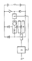
- the illustrated drive system comprises a d.c. series motor 4, which is arranged to be supplied by a battery 1.
- the motor 4 is connected to a vehicle drive wheel 8 via a gear box 7, or other suitable coupling device.
- An electronic switch 6 controls the supply of current to the motor 4, and is itself controlled by a control unit 3, which receives a brake demand signal from a pedal 2, and a current measurement signal from a current measurement device 5.
- a switch 9 controls motor and braking modes.
- the switch 9 is closed, and the d.c. motor 4 is supplied with electrical energy from the battery 1, to drive the vehicle drive wheel 8 via the gear box 7, in a more or less conventional manner.
- the control unit 3 controls the speed of the motor 4, via the electronic switch 6.
- the switch 9 is opened and the control unit 3 regulates the retardation rate of the vehicle, by altering the mark/space ratio of the electronic switch 6.
- the control unit 3 controls the mark/space ratio of the electronic switch 6, to keep the motor current Im at a constant level.
- the rate of change of mark/space ratio required to keep the current Im at the constant level indicates the retardation rate of the vehicle.
- control unit 3 If the control unit 3 detects that the retardation rate of the vehicle is either too high or too low, then the mark/space ratio of the electronic switch 6 is modified accordingly, until the desired retardation rate is achieved.
- the control unit 3 may control the mark/space ratio of the electronic switch 6 in a number of ways. For example, it may modify the demand represented by the brake demand signal from the pedal 2, so as to keep the rate of retardation approximately constant, for a given value of the brake demand signal. Alternatively, it may cause the rate of retardation to follow a predetermined variation with time.
- the illustrated system is operative to so control regenerative braking as to provide a predetermined retardation rate, largely irrespective of any changes in mass of the associated vehicle, any variations in gradient upon which the vehicle is operating, and any effects of wheel spin or skid.
Landscapes
- Engineering & Computer Science (AREA)
- Power Engineering (AREA)
- Transportation (AREA)
- Mechanical Engineering (AREA)
- Electric Propulsion And Braking For Vehicles (AREA)
Applications Claiming Priority (2)
| Application Number | Priority Date | Filing Date | Title |
|---|---|---|---|
| GB8704014 | 1987-02-20 | ||
| GB08704014A GB2201309A (en) | 1987-02-20 | 1987-02-20 | Regenerative braking systems |
Publications (2)
| Publication Number | Publication Date |
|---|---|
| EP0280478A2 true EP0280478A2 (fr) | 1988-08-31 |
| EP0280478A3 EP0280478A3 (fr) | 1989-08-16 |
Family
ID=10612651
Family Applications (1)
| Application Number | Title | Priority Date | Filing Date |
|---|---|---|---|
| EP88301420A Withdrawn EP0280478A3 (fr) | 1987-02-20 | 1988-02-19 | Système de freinage par récupération |
Country Status (2)
| Country | Link |
|---|---|
| EP (1) | EP0280478A3 (fr) |
| GB (1) | GB2201309A (fr) |
Cited By (10)
| Publication number | Priority date | Publication date | Assignee | Title |
|---|---|---|---|---|
| EP0330402A3 (fr) * | 1988-02-20 | 1990-09-05 | Fki Cableform Limited | Freinage des moteurs électriques |
| EP0459998A4 (en) * | 1989-01-19 | 1993-01-27 | Curtis Instruments, Inc. | Method and apparatus for dc motor speed control |
| EP0457594A3 (en) * | 1990-05-16 | 1993-12-22 | Honda Motor Co Ltd | A regenerative brake device for electric motor vehicles |
| EP0570934A3 (en) * | 1992-05-19 | 1994-06-01 | Toshiba Kk | Method and apparatus for controlling a battery car |
| US5362135A (en) * | 1994-02-14 | 1994-11-08 | General Motors Corporation | Brake system with adaptive offset compensation |
| US5366281A (en) * | 1994-02-14 | 1994-11-22 | General Motors Corporation | Method of initializing a brake actuator |
| US5366280A (en) * | 1994-02-14 | 1994-11-22 | General Motors Corporation | Method of adaptively homing brake actuators |
| US5423600A (en) * | 1994-02-14 | 1995-06-13 | General Motors Corporation | Brake system with brake gain shifting |
| US5539641A (en) * | 1994-02-14 | 1996-07-23 | General Motors Corporation | Brake control system method and apparatus |
| US10720860B2 (en) | 2018-01-03 | 2020-07-21 | Milwaukee Electric Tool Corporation | Electronic braking in a power tool |
Families Citing this family (4)
| Publication number | Priority date | Publication date | Assignee | Title |
|---|---|---|---|---|
| SE9100612L (sv) * | 1991-02-06 | 1992-08-07 | Lauzun Corp | Hybriddrivsystem foer motorfordon |
| EP0508367B1 (fr) * | 1991-04-09 | 1997-08-27 | Honda Giken Kogyo Kabushiki Kaisha | Système de commande de freinage pour un véhicule électrique |
| EP0531200B1 (fr) * | 1991-09-03 | 1997-03-12 | Honda Giken Kogyo Kabushiki Kaisha | Groupe de propulsion de véhicule à moteur |
| DE102007022511B4 (de) * | 2007-05-14 | 2009-07-30 | Repower Systems Ag | Windenergieanlage mit einer Verstelleinrichtung für die Rotorblätter |
Family Cites Families (10)
| Publication number | Priority date | Publication date | Assignee | Title |
|---|---|---|---|---|
| GB318231A (en) * | 1928-08-31 | 1930-07-03 | Marion Steam Shovel Co | Improvements relating to regenerative braking |
| GB1460741A (fr) * | 1973-09-10 | 1977-01-06 | Lan | |
| US4095153A (en) * | 1976-07-29 | 1978-06-13 | Westinghouse Electric Corp. | Transit vehicle electrical brake control apparatus and method |
| IN147639B (fr) * | 1977-02-11 | 1980-05-10 | Cableform Ltd | |
| US4284936A (en) * | 1979-05-02 | 1981-08-18 | General Electric Company | Chopper type propulsion system with low speed electrical braking capability for traction vehicles |
| GB2062380A (en) * | 1979-10-26 | 1981-05-20 | Cableform Ltd | Regenerative braking systems for D.C. motors |
| GB2074404B (en) * | 1980-04-11 | 1983-10-19 | Hitachi Ltd | Chopper controller for a dc motor |
| JPS56148102A (en) * | 1980-04-16 | 1981-11-17 | Hitachi Ltd | Control equipment of electric rolling stock |
| CA1173494A (fr) * | 1981-05-29 | 1984-08-28 | Canadian General Electric Company Limited | Limiteur de vitesse pour chariot electrique |
| US4468599A (en) * | 1981-12-23 | 1984-08-28 | General Electric Company | Plug current regulator |
-
1987
- 1987-02-20 GB GB08704014A patent/GB2201309A/en active Pending
-
1988
- 1988-02-19 EP EP88301420A patent/EP0280478A3/fr not_active Withdrawn
Cited By (15)
| Publication number | Priority date | Publication date | Assignee | Title |
|---|---|---|---|---|
| EP0330402A3 (fr) * | 1988-02-20 | 1990-09-05 | Fki Cableform Limited | Freinage des moteurs électriques |
| EP0459998A4 (en) * | 1989-01-19 | 1993-01-27 | Curtis Instruments, Inc. | Method and apparatus for dc motor speed control |
| US5377791A (en) * | 1990-05-16 | 1995-01-03 | Honda Giken Kogyo Kabushiki Kaisha | Regenerative brake device and a power transmission device for electric motor vehicles |
| EP0457594A3 (en) * | 1990-05-16 | 1993-12-22 | Honda Motor Co Ltd | A regenerative brake device for electric motor vehicles |
| US5446365A (en) * | 1992-05-19 | 1995-08-29 | Kabushiki Kaisha Toshiba | Method and apparatus for controlling a battery car |
| EP0570934A3 (en) * | 1992-05-19 | 1994-06-01 | Toshiba Kk | Method and apparatus for controlling a battery car |
| US5366281A (en) * | 1994-02-14 | 1994-11-22 | General Motors Corporation | Method of initializing a brake actuator |
| US5366280A (en) * | 1994-02-14 | 1994-11-22 | General Motors Corporation | Method of adaptively homing brake actuators |
| US5362135A (en) * | 1994-02-14 | 1994-11-08 | General Motors Corporation | Brake system with adaptive offset compensation |
| US5423600A (en) * | 1994-02-14 | 1995-06-13 | General Motors Corporation | Brake system with brake gain shifting |
| US5539641A (en) * | 1994-02-14 | 1996-07-23 | General Motors Corporation | Brake control system method and apparatus |
| US10720860B2 (en) | 2018-01-03 | 2020-07-21 | Milwaukee Electric Tool Corporation | Electronic braking in a power tool |
| US11075594B2 (en) | 2018-01-03 | 2021-07-27 | Milwaukee Electric Tool Corporation | Electronic braking in a power tool |
| US11695352B2 (en) | 2018-01-03 | 2023-07-04 | Milwaukee Electric Tool Corporation | Electronic braking in a power tool |
| US12166447B2 (en) | 2018-01-03 | 2024-12-10 | Milwaukee Electric Tool Corporation | Electronic braking in a power tool |
Also Published As
| Publication number | Publication date |
|---|---|
| EP0280478A3 (fr) | 1989-08-16 |
| GB2201309A (en) | 1988-08-24 |
| GB8704014D0 (en) | 1987-03-25 |
Similar Documents
| Publication | Publication Date | Title |
|---|---|---|
| EP0280478A2 (fr) | Système de freinage par récupération | |
| EP0130980B1 (fr) | Circuit de commande de freinage electrique par contre-courant | |
| US5992950A (en) | Controlled stop function for locomotives | |
| AU700435B2 (en) | Speed control system for an AC locomotive | |
| CA1292051C (fr) | Systeme d'entrainement pour vehicule automoteur | |
| JP3954145B2 (ja) | 駆動システム | |
| US4482813A (en) | Regulator system for a diesel electric locomotive | |
| JP4028015B2 (ja) | ハイブリッド式自動車用の駆動システムおよびそれを制御する方法 | |
| HU217388B (hu) | Jármű | |
| US4463289A (en) | Wheel slip control using differential signal | |
| US4668872A (en) | Electronic control system for a diesel engine, generator and electric motor power train | |
| CA2065868C (fr) | Dispositif de regulation du freinage rheostatique d'une locomotive | |
| US4392091A (en) | Vehicle propulsion control apparatus and method | |
| JPH04248301A (ja) | 電気車の制御装置 | |
| US5061883A (en) | Braking system for electric railcars including means for controlling electric brake force | |
| JPH05161208A (ja) | 電気自動車の回生制動力調整装置 | |
| JPH0654415A (ja) | 電気自動車のトルク制御装置 | |
| KR0174182B1 (ko) | 자동차의 휠 스피드 센서 진단장치 | |
| JP3488894B2 (ja) | 電動車両の電気モータ制御装置 | |
| SU670695A1 (ru) | Устройство дл управлени электроприводом поворота одноковшового экскаватора | |
| JPH0255590A (ja) | モータ制御装置 | |
| JP2004304909A (ja) | ハイブリッド車両用インバータの回生吸収システム | |
| JP3160308B2 (ja) | 電動式車両の制御装置 | |
| JPS6139886A (ja) | インバ−タ制御装置 | |
| US2214571A (en) | Electric supply system |
Legal Events
| Date | Code | Title | Description |
|---|---|---|---|
| PUAI | Public reference made under article 153(3) epc to a published international application that has entered the european phase |
Free format text: ORIGINAL CODE: 0009012 |
|
| AK | Designated contracting states |
Kind code of ref document: A2 Designated state(s): DE FR IT |
|
| PUAL | Search report despatched |
Free format text: ORIGINAL CODE: 0009013 |
|
| AK | Designated contracting states |
Kind code of ref document: A3 Designated state(s): DE FR IT |
|
| 17P | Request for examination filed |
Effective date: 19900320 |
|
| STAA | Information on the status of an ep patent application or granted ep patent |
Free format text: STATUS: THE APPLICATION IS DEEMED TO BE WITHDRAWN |
|
| 18D | Application deemed to be withdrawn |
Effective date: 19910903 |