EP0280501A1 - Detektor für momentanen Spannungsrückgang - Google Patents
Detektor für momentanen Spannungsrückgang Download PDFInfo
- Publication number
- EP0280501A1 EP0280501A1 EP88301510A EP88301510A EP0280501A1 EP 0280501 A1 EP0280501 A1 EP 0280501A1 EP 88301510 A EP88301510 A EP 88301510A EP 88301510 A EP88301510 A EP 88301510A EP 0280501 A1 EP0280501 A1 EP 0280501A1
- Authority
- EP
- European Patent Office
- Prior art keywords
- detection signal
- voltage drop
- instantaneous voltage
- output
- drop detector
- Prior art date
- Legal status (The legal status is an assumption and is not a legal conclusion. Google has not performed a legal analysis and makes no representation as to the accuracy of the status listed.)
- Granted
Links
- 238000001514 detection method Methods 0.000 claims abstract description 26
- 239000003990 capacitor Substances 0.000 claims description 4
- 230000000630 rising effect Effects 0.000 claims 1
- 230000001276 controlling effect Effects 0.000 description 1
- 238000010586 diagram Methods 0.000 description 1
- 230000000694 effects Effects 0.000 description 1
- 238000000034 method Methods 0.000 description 1
- 230000001105 regulatory effect Effects 0.000 description 1
Images

Classifications
-
- H—ELECTRICITY
- H04—ELECTRIC COMMUNICATION TECHNIQUE
- H04B—TRANSMISSION
- H04B1/00—Details of transmission systems, not covered by a single one of groups H04B3/00 - H04B13/00; Details of transmission systems not characterised by the medium used for transmission
- H04B1/38—Transceivers, i.e. devices in which transmitter and receiver form a structural unit and in which at least one part is used for functions of transmitting and receiving
- H04B1/40—Circuits
- H04B1/44—Transmit/receive switching
-
- H—ELECTRICITY
- H02—GENERATION; CONVERSION OR DISTRIBUTION OF ELECTRIC POWER
- H02H—EMERGENCY PROTECTIVE CIRCUIT ARRANGEMENTS
- H02H3/00—Emergency protective circuit arrangements for automatic disconnection directly responsive to an undesired change from normal electric working condition with or without subsequent reconnection ; integrated protection
- H02H3/24—Emergency protective circuit arrangements for automatic disconnection directly responsive to an undesired change from normal electric working condition with or without subsequent reconnection ; integrated protection responsive to undervoltage or no-voltage
- H02H3/247—Emergency protective circuit arrangements for automatic disconnection directly responsive to an undesired change from normal electric working condition with or without subsequent reconnection ; integrated protection responsive to undervoltage or no-voltage having timing means
Definitions
- the present invention relates to an instantaneous voltage drop detector, and more particularly to a detector for detecting an instantaneous voltage drop in a battery used for a mobile radiotelephone and the like.
- a mobile radiotelephone when a voltage drop occurs in a battery during a telephone conversation which the battery supplies power to the telephone, its transmitter/receiver section is controlled depending on the period of voltage drop. More specifically, if the battery voltage is restored to a normal level within a predetermined period of time, for example, three seconds from the voltage drop no control is conducted on the transmitter/receiver section and the telephone conversation is maintained. On the other hand, if the normal voltage level is restored later than three seconds after the voltage drop, the telephone is forced to be returned to waiting state. Unless the normal voltage level is restored even after the lapse of three seconds from the voltage drop, the mobile radiotelephone stays in an inoperable state.
- the battery output is supplied respectively to a reset circuit and to a regulator of which output is connected to an RC time constant circuit.
- the outputs from the reset circuit and the RC time constant circuit are used for logically judging whether the radiotelephone should keep the conversation or should shift to the waiting state.
- the RC time constant circuit provides a time, e.g., three seconds to make this judgment.
- the conventional instantaneous voltage drop detector is inconvenient in that a detection delay occurs because the regulator output is used for the above-mentioned judgment. Moreover, when the battery output voltage is lowered only to the median voltage level, which is somewhere between the uppermost and lowermost levels, the detector often cannot detect such a drop due to the effect of the RC time constant circuit connected to the regulator output. Therefore, the conventional detector cannot correctly detect the instantaneous voltage drop.
- An object of the present invention is to provide an instantaneous voltage drop detector which has no delay in the detection of instantaneous voltage drop without resorting to a specific additional circuit element.
- Another object of this invention is to provide an instantaneous voltage drop detector which can detect an instantaneous voltage drop even when a voltage drop due to the failure falls only below a median voltage level.
- an instantaneous voltage drop detector comprising: power supply means for supplying power at least to an utilization circuit, first detecting means for detecting a drop in an output voltage of the power supply means which falls below a first predetermined level, and supplying a first detection signal having a second predetermined level different from the first predetermined level, second detecting means for judging whether or not the first detection signal continues for more than a predetermined time period and if it continues beyond the predetermined time period, producing a second detection signal, and control means responsive to the first and second detection signals for controlling the utilization circuit.
- an output voltage from a battery 1 (for example +13 V) is regulated to be at a predetermined level (for instance +6 V) by a regulator 2, and supplied to a comparator 4 and a transmitter/receiver (TX/RX) 7.
- the TX/RX 7 includes a handset unit (not shown).
- the output voltage from the battery 1 is also supplied to a reset circuit 3.
- the reset circuit 3 can detect not only a voltage drop to the lowermost level, i.e., zero volts but a drop to only a median level in the output of the battery 1, and changes its output level from high to low when it detects such drops. When the output voltage from the battery 1 has been restored to the normal level, the reset circuit 3 changes its output level from low to high.
- the output from the reset circuit 3 is supplied to a control unit 6 for logical judgement in order to control the TX/RX 7 after the voltage drop as well as to the comparator 4 through a CR time constant circuit comprising a capacitor C1 and a resistor R1.
- the CR time constant circuit provides a judgement time (three seconds in this instance) to determine whether or not the conversation should be maintained.
- the comparator 4 compares an input voltage thereto with a predetermined reference level Vref, and only when the input voltage exceeds Vref, supplies an output voltage to an input/output (I/O) port.
- the I/O port 5 supplies a high-level signal when it receives an input voltage, and supplies a low-level signal when it receives no input voltage, to the control unit 6.
- the control unit 6 Based on the outputs from the reset circuit 3 and the I/O port 5 during the conversation, the control unit 6 logically judges whether the TX/RX 7 is maintained at the present conversation mode or should be shifted to the waiting mode. The logical judgment will be described in more detail referring to FIG. 5 later.
- FIG. 2 is a circuit showing the reset circuit 3 shown in FIG. 1.
- the battery output voltage supplied, through an input terminal 21, to a CR time constant circuit comprising a capacitor C2 and a resistor R2.
- the battery output voltage is also supplied to a resistor R3 and a diode D1 connected between a base and a collector of a switching transistor Tr1.
- the detectable level in battery voltage drop can be determined by the voltage between the base and the emitter of the transistor Tr1.
- the detectable level represents a median level somewhere between the uppermose and lowermost voltages of battery 1.
- the CR time constant circuit absorbs minute fluctuations in input voltages.
- the reset output is obtained from a terminal 22 via an inverter I1 connected to the collector of the transistor Tr1.
- the detectable level may be changed.
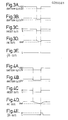
- FIGS. 3A to 3E and 4A to 4E are time charts showing waveforms at various sections in the detector of FIG. 1, and representatives of power failures which continue a predetermined time period (three seconds here) and less than this period, respectively.
- the output from the reset circuit 3 is changed from a high level to a low level, and then to a high level as shown in FIG. 3C.
- the circuit 3 produces a reset output.
- the output from the RC time constant circuit becomes a waveform shown in FIG. 3D due to the time constant thereof, and does not drop below the predetermined rererence level Vref. Therefore, the output from the I/O port 5 stays at a low level as shown in FIG. 3E.
- the output from the reset circuit 3 is shifted from the high level to the low level, and then to the high level. In other words, it supplies a reset output.
- the output from the RC time constant circuit becomes a waveform shown in FIG. 4D due to the time constant thereof, and when it drops below the predetermined reference level Vref, the I/O port 5 outputs a high level pulse as shown in FIG. 4E.
- the reset output as shown in FIGS. 3C and 4C is naturally obtained from the terminal 22, and when it lowers only to the median voltage level as shown in FIGS. 3B and 4B, the reset output as shown in FIGS. 3C and 4C can be obtained from the terminal 22 so far as it is above the threshold level between the base and the emitter of the transistor Tr1.
- the detector of the present invention there occurs no delay in detection from the start of the drop of the battery output voltage.
- the present detector can also detect power drop only to a median level.
- the conversation state is maintained if an instantaneous power failure is for less than three seconds, but the mode goes into the waiting state if the voltage is restored after three seconds.
- Step 43 the process does not proceed to the next step.
- the absence of a reset output means either that the battery output is normal or that the power is cut off, and indicates that there is no necessity of control.
- the output from the I/O port 5 is judged whether it is at a high level or not at Step 44. If it is at the high level, it means that the voltage is restored to the normal voltage after three seconds, and thus the TX/RX 7 is controlled to go into the waiting state at Step 45. If it is not at the high level, it means that the power drop is restored within three seconds, the TX/RX 7 is controlled to maintain the current speech state at Step 46.
- a regulator output is not used for detection of instantaneous voltage drop, the battery voltage drops can be detected without any delay from the start of actual drop. It further detects battery voltage drop even if it does not drop to the 0 V level but to the median level by directly connecting the reset circuit with the CR time constant circuit to thereby enable precise detection of instantaneous voltage drop.
Landscapes
- Engineering & Computer Science (AREA)
- Computer Networks & Wireless Communication (AREA)
- Signal Processing (AREA)
- Measurement Of Current Or Voltage (AREA)
- Emergency Protection Circuit Devices (AREA)
Applications Claiming Priority (2)
| Application Number | Priority Date | Filing Date | Title |
|---|---|---|---|
| JP1987025058U JPS63137527U (de) | 1987-02-23 | 1987-02-23 | |
| JP25058/87U | 1987-02-23 |
Publications (2)
| Publication Number | Publication Date |
|---|---|
| EP0280501A1 true EP0280501A1 (de) | 1988-08-31 |
| EP0280501B1 EP0280501B1 (de) | 1994-01-12 |
Family
ID=12155325
Family Applications (1)
| Application Number | Title | Priority Date | Filing Date |
|---|---|---|---|
| EP88301510A Expired - Lifetime EP0280501B1 (de) | 1987-02-23 | 1988-02-23 | Detektor für momentanen Spannungsrückgang |
Country Status (3)
| Country | Link |
|---|---|
| US (1) | US4912774A (de) |
| EP (1) | EP0280501B1 (de) |
| JP (1) | JPS63137527U (de) |
Cited By (4)
| Publication number | Priority date | Publication date | Assignee | Title |
|---|---|---|---|---|
| EP0439319A1 (de) * | 1990-01-23 | 1991-07-31 | Nec Corporation | Autotelefonapparat mit einer Detektionseinrichrung für ein Absinken der Versorgungsspannung |
| EP0488240A1 (de) * | 1990-11-30 | 1992-06-03 | Hitachi, Ltd. | Wechselrichter versehen mit einem Kreis zur Regelung der elektrischen Entladung eines Gleichstrom-Glättungskondensators und Verfahren zur Regelung desselben |
| EP0607919A3 (de) * | 1993-01-20 | 1994-11-17 | Mitsubishi Electric Corp | Tragbares Fernsprechgerät. |
| EP1429442A3 (de) * | 2002-12-11 | 2005-06-08 | Curitel Communications, Inc. | Schaltungsanordnung und Verfahren zur Vermeidung des unbeabsichtigten Ausschaltens eines mobilen Endgerätes |
Families Citing this family (7)
| Publication number | Priority date | Publication date | Assignee | Title |
|---|---|---|---|---|
| JP3015443B2 (ja) * | 1990-10-11 | 2000-03-06 | 株式会社東芝 | 無線電話装置 |
| US5175871A (en) * | 1991-08-08 | 1992-12-29 | Ericsson/Ge Mobile Communication Holding Inc. | Power amplifier for a cellular telephone |
| US6571091B1 (en) * | 1995-05-30 | 2003-05-27 | Motorola, Inc. | Power control method and apparatus suitable for use in a radio communication device |
| JP2002287832A (ja) * | 2001-03-27 | 2002-10-04 | Sharp Corp | 送信装置 |
| JP4849884B2 (ja) * | 2005-12-19 | 2012-01-11 | セイコーインスツル株式会社 | 生体情報送信機 |
| KR101688144B1 (ko) * | 2010-06-16 | 2016-12-20 | 엘지전자 주식회사 | 이동통신 단말기 및 그의 전원 관리 방법 |
| CN112415294B (zh) * | 2019-08-22 | 2024-11-19 | 上海中兴软件有限责任公司 | 电压瞬间下降的检测电路及车载诊断系统 |
Citations (3)
| Publication number | Priority date | Publication date | Assignee | Title |
|---|---|---|---|---|
| US3670246A (en) * | 1970-03-16 | 1972-06-13 | Forbro Design Corp | Under-voltage monitoring device having time delay means for regulated power supplies |
| GB1424550A (en) * | 1971-11-16 | 1976-02-11 | Addressograph Multigraph | Power-fail detection system |
| EP0203781A1 (de) * | 1985-05-23 | 1986-12-03 | Nec Corporation | Batteriegespeistes mobiles Kommunikationsgerät mit Senderrückstellfunktion |
Family Cites Families (2)
| Publication number | Priority date | Publication date | Assignee | Title |
|---|---|---|---|---|
| JPS59170921A (ja) * | 1983-03-18 | 1984-09-27 | Hitachi Ltd | 停電検出回路 |
| DE3534574C3 (de) * | 1984-09-29 | 1998-05-20 | Pioneer Electronic Corp | Informationswiedergabeeinrichtung in einem Kraftfahrzeug |
-
1987
- 1987-02-23 JP JP1987025058U patent/JPS63137527U/ja active Pending
-
1988
- 1988-02-22 US US07/158,610 patent/US4912774A/en not_active Expired - Lifetime
- 1988-02-23 EP EP88301510A patent/EP0280501B1/de not_active Expired - Lifetime
Patent Citations (3)
| Publication number | Priority date | Publication date | Assignee | Title |
|---|---|---|---|---|
| US3670246A (en) * | 1970-03-16 | 1972-06-13 | Forbro Design Corp | Under-voltage monitoring device having time delay means for regulated power supplies |
| GB1424550A (en) * | 1971-11-16 | 1976-02-11 | Addressograph Multigraph | Power-fail detection system |
| EP0203781A1 (de) * | 1985-05-23 | 1986-12-03 | Nec Corporation | Batteriegespeistes mobiles Kommunikationsgerät mit Senderrückstellfunktion |
Non-Patent Citations (1)
| Title |
|---|
| ELECTRONICS, vol. 42, no. 25, 12th December 1974, pages 109,111; K.C. SEINO: "Power-failure detector is good for short lapses" * |
Cited By (8)
| Publication number | Priority date | Publication date | Assignee | Title |
|---|---|---|---|---|
| EP0439319A1 (de) * | 1990-01-23 | 1991-07-31 | Nec Corporation | Autotelefonapparat mit einer Detektionseinrichrung für ein Absinken der Versorgungsspannung |
| AU638530B2 (en) * | 1990-01-23 | 1993-07-01 | Nec Corporation | Automobile radio telephone apparatus capable of detecting a drop of power source voltage |
| US6173170B1 (en) | 1990-01-23 | 2001-01-09 | Nec Corporation | Radio telephone apparatus capable of detecting a drop of power source voltage |
| EP0488240A1 (de) * | 1990-11-30 | 1992-06-03 | Hitachi, Ltd. | Wechselrichter versehen mit einem Kreis zur Regelung der elektrischen Entladung eines Gleichstrom-Glättungskondensators und Verfahren zur Regelung desselben |
| EP0607919A3 (de) * | 1993-01-20 | 1994-11-17 | Mitsubishi Electric Corp | Tragbares Fernsprechgerät. |
| US5551077A (en) * | 1993-01-20 | 1996-08-27 | Mitsubishi Denki Kabushiki Kaisha | Portable telephone equipment with condition restoration |
| EP1429442A3 (de) * | 2002-12-11 | 2005-06-08 | Curitel Communications, Inc. | Schaltungsanordnung und Verfahren zur Vermeidung des unbeabsichtigten Ausschaltens eines mobilen Endgerätes |
| US7205683B2 (en) | 2002-12-11 | 2007-04-17 | Curitel Communications, Inc | Circuit for preventing unintentional power off of mobile terminal and method thereof |
Also Published As
| Publication number | Publication date |
|---|---|
| EP0280501B1 (de) | 1994-01-12 |
| JPS63137527U (de) | 1988-09-09 |
| US4912774A (en) | 1990-03-27 |
Similar Documents
| Publication | Publication Date | Title |
|---|---|---|
| EP0280501A1 (de) | Detektor für momentanen Spannungsrückgang | |
| EP0192832B1 (de) | Fehlerdetektor mit Mehrfachfunktion für einen Drehstromgenerator | |
| JPH0927836A (ja) | 停電検出機能を備えたコードレス電話機 | |
| US5440220A (en) | Battery discharge control circuit | |
| US5142165A (en) | Power off/on delay circuit to prevent lockout | |
| US5027328A (en) | Memory drive device and method | |
| US4982443A (en) | Instantaneous voltage drop detector for DC power source | |
| US4618780A (en) | Power-off detection circuit for an electronic apparatus | |
| US6667604B2 (en) | Power supply circuit with continued power generation after switch turn-off | |
| US4392121A (en) | Receiver for A.C. electrical supply signalling arrangement | |
| US4184053A (en) | Ringing signal detector | |
| US6535405B2 (en) | Power supply device having two AC power inputs | |
| US6944003B2 (en) | Semiconductor integrated circuit with voltage-detecting circuit and signal transmitting and receiving system | |
| EP0385781A2 (de) | Detektionsschaltung für Radiofrequenzenergie | |
| US5701240A (en) | Apparatus for powering a transmitter from a switched leg | |
| JPH0728532A (ja) | 安定化電源の過負荷保護回路 | |
| JPH08274795A (ja) | バスを介して電圧レベルの変化した形態で伝送された信号を受信するための回路装置 | |
| JPH0413941B2 (de) | ||
| JP3057930B2 (ja) | 端末網制御装置 | |
| US4309623A (en) | Power source device for electronic counting system | |
| EP0186740B1 (de) | Netzfrequenzdetektorsystem | |
| US6223024B1 (en) | Intermittent control reception circuit for low consumptive current sake | |
| US6445721B1 (en) | Laser diode light emission sensing circuit | |
| JPH0477326B2 (de) | ||
| JP2006506861A (ja) | データ伝送ユニットへのエネルギー供給装置 |
Legal Events
| Date | Code | Title | Description |
|---|---|---|---|
| PUAI | Public reference made under article 153(3) epc to a published international application that has entered the european phase |
Free format text: ORIGINAL CODE: 0009012 |
|
| 17P | Request for examination filed |
Effective date: 19880317 |
|
| AK | Designated contracting states |
Kind code of ref document: A1 Designated state(s): GB NL SE |
|
| 17Q | First examination report despatched |
Effective date: 19910313 |
|
| GRAA | (expected) grant |
Free format text: ORIGINAL CODE: 0009210 |
|
| AK | Designated contracting states |
Kind code of ref document: B1 Designated state(s): GB NL SE |
|
| PG25 | Lapsed in a contracting state [announced via postgrant information from national office to epo] |
Ref country code: NL Effective date: 19940112 |
|
| PG25 | Lapsed in a contracting state [announced via postgrant information from national office to epo] |
Ref country code: GB Effective date: 19940412 |
|
| NLV1 | Nl: lapsed or annulled due to failure to fulfill the requirements of art. 29p and 29m of the patents act | ||
| PLBE | No opposition filed within time limit |
Free format text: ORIGINAL CODE: 0009261 |
|
| STAA | Information on the status of an ep patent application or granted ep patent |
Free format text: STATUS: NO OPPOSITION FILED WITHIN TIME LIMIT |
|
| GBPC | Gb: european patent ceased through non-payment of renewal fee |
Effective date: 19940412 |
|
| 26N | No opposition filed | ||
| EAL | Se: european patent in force in sweden |
Ref document number: 88301510.9 |
|
| PGFP | Annual fee paid to national office [announced via postgrant information from national office to epo] |
Ref country code: SE Payment date: 19980205 Year of fee payment: 11 |
|
| PG25 | Lapsed in a contracting state [announced via postgrant information from national office to epo] |
Ref country code: SE Free format text: LAPSE BECAUSE OF NON-PAYMENT OF DUE FEES Effective date: 19990224 |
|
| EUG | Se: european patent has lapsed |
Ref document number: 88301510.9 |