EP0280759B1 - Agencement de câbles de puissance électriques pour la protection contre les explosions de gaz et/ou de mélanges poussière/air, en particulier pour l'exploitation au fond - Google Patents
Agencement de câbles de puissance électriques pour la protection contre les explosions de gaz et/ou de mélanges poussière/air, en particulier pour l'exploitation au fond Download PDFInfo
- Publication number
- EP0280759B1 EP0280759B1 EP87105308A EP87105308A EP0280759B1 EP 0280759 B1 EP0280759 B1 EP 0280759B1 EP 87105308 A EP87105308 A EP 87105308A EP 87105308 A EP87105308 A EP 87105308A EP 0280759 B1 EP0280759 B1 EP 0280759B1
- Authority
- EP
- European Patent Office
- Prior art keywords
- short
- circuit
- arrangement according
- isolating
- switches
- Prior art date
- Legal status (The legal status is an assumption and is not a legal conclusion. Google has not performed a legal analysis and makes no representation as to the accuracy of the status listed.)
- Expired - Lifetime
Links
- 239000000203 mixture Substances 0.000 title claims description 12
- 238000004880 explosion Methods 0.000 title claims description 6
- 239000000428 dust Substances 0.000 title description 2
- 239000004020 conductor Substances 0.000 claims description 10
- 238000001514 detection method Methods 0.000 claims description 10
- 239000003990 capacitor Substances 0.000 claims description 6
- 238000005065 mining Methods 0.000 claims description 3
- 230000005520 electrodynamics Effects 0.000 claims description 2
- 230000001939 inductive effect Effects 0.000 claims description 2
- 238000012544 monitoring process Methods 0.000 claims description 2
- 238000002592 echocardiography Methods 0.000 claims 1
- 230000007935 neutral effect Effects 0.000 claims 1
- 238000000926 separation method Methods 0.000 claims 1
- 230000001960 triggered effect Effects 0.000 claims 1
- 230000006378 damage Effects 0.000 description 12
- 230000004907 flux Effects 0.000 description 8
- VNWKTOKETHGBQD-UHFFFAOYSA-N methane Chemical compound C VNWKTOKETHGBQD-UHFFFAOYSA-N 0.000 description 8
- 230000005540 biological transmission Effects 0.000 description 7
- 239000002360 explosive Substances 0.000 description 7
- 238000010586 diagram Methods 0.000 description 5
- 230000004913 activation Effects 0.000 description 4
- 230000000903 blocking effect Effects 0.000 description 4
- 239000007789 gas Substances 0.000 description 4
- 238000009413 insulation Methods 0.000 description 4
- 238000000034 method Methods 0.000 description 4
- 230000001681 protective effect Effects 0.000 description 4
- 230000008901 benefit Effects 0.000 description 3
- 230000008859 change Effects 0.000 description 3
- 239000003245 coal Substances 0.000 description 3
- 238000002955 isolation Methods 0.000 description 3
- 238000004804 winding Methods 0.000 description 3
- 230000001133 acceleration Effects 0.000 description 2
- 238000013461 design Methods 0.000 description 2
- 238000009434 installation Methods 0.000 description 2
- 230000008569 process Effects 0.000 description 2
- 125000006850 spacer group Chemical group 0.000 description 2
- XLYOFNOQVPJJNP-UHFFFAOYSA-N water Substances O XLYOFNOQVPJJNP-UHFFFAOYSA-N 0.000 description 2
- 229910000831 Steel Inorganic materials 0.000 description 1
- 239000004566 building material Substances 0.000 description 1
- 238000004891 communication Methods 0.000 description 1
- 230000001419 dependent effect Effects 0.000 description 1
- 238000006073 displacement reaction Methods 0.000 description 1
- 230000000694 effects Effects 0.000 description 1
- 238000010891 electric arc Methods 0.000 description 1
- 238000004146 energy storage Methods 0.000 description 1
- 238000005516 engineering process Methods 0.000 description 1
- 238000011156 evaluation Methods 0.000 description 1
- 230000006870 function Effects 0.000 description 1
- 238000005259 measurement Methods 0.000 description 1
- 230000007246 mechanism Effects 0.000 description 1
- 238000003801 milling Methods 0.000 description 1
- 238000005457 optimization Methods 0.000 description 1
- 230000036961 partial effect Effects 0.000 description 1
- 230000000149 penetrating effect Effects 0.000 description 1
- 230000035515 penetration Effects 0.000 description 1
- 230000000737 periodic effect Effects 0.000 description 1
- 230000009993 protective function Effects 0.000 description 1
- 230000009257 reactivity Effects 0.000 description 1
- 230000002787 reinforcement Effects 0.000 description 1
- 230000002040 relaxant effect Effects 0.000 description 1
- 239000010959 steel Substances 0.000 description 1
- 239000000126 substance Substances 0.000 description 1
- 230000001360 synchronised effect Effects 0.000 description 1
- 230000036962 time dependent Effects 0.000 description 1
- 238000011144 upstream manufacturing Methods 0.000 description 1
- 238000009423 ventilation Methods 0.000 description 1
Images




Classifications
-
- H—ELECTRICITY
- H01—ELECTRIC ELEMENTS
- H01H—ELECTRIC SWITCHES; RELAYS; SELECTORS; EMERGENCY PROTECTIVE DEVICES
- H01H33/00—High-tension or heavy-current switches with arc-extinguishing or arc-preventing means
- H01H33/60—Switches wherein the means for extinguishing or preventing the arc do not include separate means for obtaining or increasing flow of arc-extinguishing fluid
- H01H33/66—Vacuum switches
- H01H33/666—Operating arrangements
-
- H—ELECTRICITY
- H02—GENERATION; CONVERSION OR DISTRIBUTION OF ELECTRIC POWER
- H02H—EMERGENCY PROTECTIVE CIRCUIT ARRANGEMENTS
- H02H3/00—Emergency protective circuit arrangements for automatic disconnection directly responsive to an undesired change from normal electric working condition with or without subsequent reconnection ; integrated protection
- H02H3/02—Details
- H02H3/021—Details concerning the disconnection itself, e.g. at a particular instant, particularly at zero value of current, disconnection in a predetermined order
- H02H3/023—Details concerning the disconnection itself, e.g. at a particular instant, particularly at zero value of current, disconnection in a predetermined order by short-circuiting
-
- H—ELECTRICITY
- H02—GENERATION; CONVERSION OR DISTRIBUTION OF ELECTRIC POWER
- H02H—EMERGENCY PROTECTIVE CIRCUIT ARRANGEMENTS
- H02H7/00—Emergency protective circuit arrangements specially adapted for specific types of electric machines or apparatus or for sectionalised protection of cable or line systems, and effecting automatic switching in the event of an undesired change from normal working conditions
- H02H7/22—Emergency protective circuit arrangements specially adapted for specific types of electric machines or apparatus or for sectionalised protection of cable or line systems, and effecting automatic switching in the event of an undesired change from normal working conditions for distribution gear, e.g. bus-bar systems; for switching devices
- H02H7/222—Emergency protective circuit arrangements specially adapted for specific types of electric machines or apparatus or for sectionalised protection of cable or line systems, and effecting automatic switching in the event of an undesired change from normal working conditions for distribution gear, e.g. bus-bar systems; for switching devices for switches
-
- H—ELECTRICITY
- H01—ELECTRIC ELEMENTS
- H01H—ELECTRIC SWITCHES; RELAYS; SELECTORS; EMERGENCY PROTECTIVE DEVICES
- H01H3/00—Mechanisms for operating contacts
- H01H3/22—Power arrangements internal to the switch for operating the driving mechanism
- H01H3/222—Power arrangements internal to the switch for operating the driving mechanism using electrodynamic repulsion
Definitions
- the invention relates to an arrangement for electrical power supply systems for preventing explosions of gas and / or dust-air mixtures according to the preamble of claim 1.
- the invention can be used, for example, in the chemical industry, where explosive mixtures consisting of different gases also occur in the area of power supply systems, or in the milling industry, where explosive dust-air mixtures are found in the area of electrical power supply systems, it is used in the following their main area of application, which is the underground operation.
- explosive methane-air mixtures and coal dust-air mixtures occur in underground coal mining.
- electrical energy must also be transmitted under external circumstances, which may lead to mechanical damage to the lines. This applies, for example, to trailing cables from shearer loaders during dismantling. It also strives for high-voltage power transmission where it was previously excluded for safety reasons and low-voltage power supply is mandatory.
- the advantages of high-voltage energy transmission lie in the good building material economy of the lines and cables.
- the invention is based on the fact that the increase in the mechanical strength of the electrical lines, for example through multi-layer reinforcement of steel wire as line protection, has its natural limit, on the one hand, in the technical effort and manageability, but, on the other hand, in the finally great strength, so that there is a sufficiently strong damage effect on the line removes their protective functions.
- three-phase networks with frequencies between 50 to 60 Hz can be assumed with the extensive use of networks with an ungrounded star point.
- the invention has for its object to provide an arrangement of the type mentioned, which prevents electrical lines lying outside the area of intrinsic safety from becoming the ignition source of explosive gases, vapors, mists or dusts.
- the invention enables the blocking of any further energy supply to the fault location. This happens from the infeed side and from the end on the load side when the load is reactive (motors, transformers, capacitor batteries as phase shifters). According to the invention this becomes created a line protection system with the help of the fast-acting disconnector and short-circuiter, in which the current flowing to a source of error in the line is limited and switched off so quickly that the ignition of a gas, in particular methane or dust-air mixture is excluded.
- This source of error can be caused by mechanical damage to the line, e.g.
- the source of the fault is determined using the earth fault detection system, which, however, operates so quickly that it responds before a gas-air mixture is ignited or a line end that has become free can whip up and ignite dust or an electric arc is generated.
- the fast-acting short-circuiters with their resistances before the start of the disconnection process serve to limit the voltage drop at the disconnectors to voltage values below the arc voltage. Since the line to the fault location is low-induction - and this applies to the lines in power engineering - the isolating switches open without ionizing their switching paths, which prevents arcing. With their resistances, the short-circuiters load the network and the load formed, for example, by a motor with the respective short-circuit current, but the isolating switches are so fast that they open, for example, within a current half-oscillation. As a result, the activation of the short-circuiters can be limited to this time, so that they automatically switch to the blocking state when the current crosses zero.
- a disconnector is obtained, whose linear drive is either designed according to the type and mode of operation of a transformer, whereby a coil with a pulsed current in a disc made of electrically conductive material induces currents as a single-winded short-circuited secondary winding, or consists of two coils with a pulsed current and opposing magnetic field.
- a switch drive enables a compact design with a high switching speed and axial acceleration forces of the order of ten to five newtons (initial value) or ten to four newtons (average value).
- the linear drives are fed from capacitors as energy storage.
- This type of supply enables the optimization of the drive by the fact that the coil or coils of the drive together with the assigned capacitor form a resonant circuit, the parameters of which are optimized to achieve a maximum acceleration force of the drives.
- This feeding method of the linear drives is also independent of the short-circuit currents occurring in the network.
- the embodiment according to claim 6 provides for the combination of a disconnector with an upstream electronic short-circuiter in the energy flow direction (based on the fault).
- the switching elements of the short-circuiter are actuated inductively via the supply circuits of the linear drives of the isolating switch, so that when the isolating switch is actuated, the short-circuiting device is inevitably actuated and the inevitably arcing-free opening of the isolating switch elements and thus the instantaneous interruption of the current via the isolating switch elements are ensured.
- the activation of the thyristors of the short-circuiter can be limited to a short period of time.
- the thyristors remain conductive until approximately zero current and then automatically switch to the blocking state.
- the duration of the short-circuit current caused by the short-circuiter is therefore also with about 10 to 15 milliseconds on the order of so-called current-limiting switching devices and about a factor of 5 below the opening time of conventional circuit breakers.
- Short-circuiters and disconnectors are expediently grouped together structurally.
- Such a switch can then also be used according to claim 7. Due to the inevitable activation of the switching elements of the short-circuiting device, the time limitation of the conductive state of these switching elements and the short mechanical intrinsic time of the isolating switch, the combination of short-circuiting device and isolating switch fulfills the requirements placed on circuit breakers (disconnection of short-circuit currents). Due to the omission of a special circuit breaker, there are considerable advantages, particularly in tight spaces.
- the remote-controlled switch-on device of the circuit breaker operated with external energy enables the operation of this circuit breaker as a contactor.
- the earth fault detection in the embodiment according to claim 9 provides a solution for the three-phase systems which are largely common in mining with an ungrounded star point. Every mechanical damage causes a time-dependent ohmic fault resistance between one or more outer conductors and the protective conductor, which is then prone to reactivity at the beginning of the damage. This shift in voltage conditions generates three magnetic fluxes via voltage converters and a differential transformer in the event of a fault in the network, which are asymmetrical in the differential transformer. The resulting magnetic flux provides a secondary voltage signal at the output of the differential transformer.
- each individual line can also be achieved according to the invention.
- the means specified in claim 10 are used for this purpose.
- Periodic, rectangular-like pulses of suitable rise time and pulse width are fed in at one end of the line and the echo pulses received here are continuously compared with the echo pulses of the undamaged line. Any mechanical damage to the line and any ground fault caused by insulation faults cause a change in the wave resistance of the affected line wire and thus a change in the structure of the echograms.
- the error detection time of this method can be reduced to twice the signal propagation time over the entire length of the line. This value is also the Lower limit for the pulse interval of the injected rectangular-like pulses.
- the advantage of such a design is the selective protection of each individual line that belongs to a common network district.
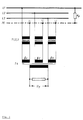
- Arcing on the switching paths of the isolating switches (Q1 and Q2) can be prevented if the electronic short-circuiters (K1 and K2) with their resistances (R1 and R2) before the start of the Isolation process in (Q1 and Q2) limit the voltage drop at (Q1 and Q2) to a few volts. If the line to the fault location is low-induction, which is the case here, open (Q1 and Q2) without ionizing the switching path and thus without arcing.
- Short-circuiters K1, K2 and isolating switching sections (Q1, Q2) are structurally combined to form high-speed switches (T1 and T2).
- Such a disconnector is shown in FIG. 2. It consists of the three thyristors (V1, V2 and V3) in a delta connection and the downstream vacuum switching tubes (Q1, Q2 and Q3).
- the switching tubes are opened by electrodynamic linear drives (ed A1, ed A2 and ed A3), whereby the capacitors (C1, C2 and C3) discharge via thyristors (V4, V5 and V6) onto the drive coils of the linear drives.
- the existing disc is accelerated from the coil as a "short-circuit ring" and serves as a switching tube drive.
- the repulsive force is of the order of ten to five newtons (initial value) or ten to four newtons as the mean.
- the thyristors (V1 to V3) are ignited by the discharge current of the linear drives (or by their time differential) via the inductive converters (T1, T2 and T3).
- FIG. 3 shows a line monitor for a symmetrical three-phase system with an ungrounded star point (N).
- N ungrounded star point
- a system shows equally large voltages between (N) and the outer conductors (L1, L2 and L3).
- RF ohmic fault resistance
- PE protective conductor
- the outer conductors (L1, L2 and L3) therefore assume unequal voltages against (PE).
- this shift in the voltage conditions in the faulty three-phase system leads to an electrical signal.
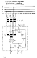
- FIG. 4 An earth fault detection unit is shown in FIG. 4. It works according to the principle described above in connection with the explanation of FIG. 3 with a differential transformer (T4) fed by voltage transformers (T1 to T3), the resulting magnetic flux of which results in zero when the network is undisturbed. If the network is faulty, the non-zero magnetic flux in (T4) generates a voltage signal via the Graetz bridge (G2).
- the three vacuum tubes (10 to 12) are arranged between a base plate (13) and an intermediate plate (14). Spacer bolts, e.g. shown at (15), hold the intermediate plate (14) via spacer rings (16 and 17). A vacuum tube is provided for each outer conductor of the three-phase system.
- the assigned parts are identical in all three cases.
- a shift linkage (19) passes through a transformer, which has a primary winding (20).
- the secondary winding of the transformer consists of the disc (21), which acts on the shift linkage (19) via a nut (22).
- the upper end of the shift linkage (19) is a rod (24) with a round cross section, which has a chamfer of a cylindrical recess (27) shown at (25 and 26).
- the rod (24) runs in a sleeve (28), the upper end of which is provided with a thread (29) for the cover cap (23).
- the sleeve is surrounded by a helical spring (30) which is supported with its upper end on the inside (31) of the cap (23) and with its lower end loads the upper cylindrical part (32) of a locking ring (33).
- the ring has a flange (34) which separates the upper cylindrical part (32) from a lower cylindrical section (35).
- the ring has an inner cylindrical recess (36) for receiving balls (37) which serve as locking bodies.
- the flange serves for the axial displacement of an actuating ring (40) with which auxiliary switches (38) can be actuated which are seated on a mounting plate (39).
- the locking mechanism described in FIGS. 6 and 8 functions as follows: In the closed state of the Switch the balls (37) are above the cylindrical recess (27) of the rod (24). As soon as the linear drive accelerates the shift linkage (19) upwards, the balls (37) are guided inwards as a result of the recess (36) and the prestressed spring (30) until they come into the recess (27) via the chamfer (26) . This releases the locking ring (33) which the relaxing spiral spring (30) leads downwards, whereby the balls (37) are held in the recess (27) of the rod (24). As a result, the rod (24) can no longer be returned downwards if there is no drive force.
- the switch can be closed as soon as the locking ring (33) is pressed upwards over the flange (34) while simultaneously compressing the coil spring (30). This can be done manually, but also electrically, pneumatically or hydraulically.
- a fault location device consisting of a pulse generator and an evaluation unit, hereinafter referred to as electronics, continuously monitors a line in operation at the network end.
- Mechanical damage eg penetrating foreign bodies
- the switch-off command to the line-side circuit breaker follows from the deviation of the echogram.
- the message is sent from a receiver to the local circuit breaker. Since control lines between the network and load side are not to be used, the load-side receiver must obtain the switch-off command from a suitable coding of the pulses fed in on the network side.
- One possibility for this is the polarity reversal of that of the pulse generator emitted pulses after detection of the faulty state.
- the pulse rate of the location pulses should be above 10 kHz if possible, so that a maximum of 100 mü are required to detect / report an error. Conversely, twice the signal transit time on the line represents the lower limit for the spacing of the transmission pulses.
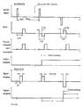
- the control of the load-side receiver is shown schematically in FIG. 10.
- the fault location device installed on the network side (“device side”) feeds positive pulses at 10 kHz; After reflection at the high-frequency open end of the line, the echo appears after double the signal delay t on the fault location device with positive polarity. If an error occurs, for example as a final wire shield, the echo reaches the fault locator after the time 2 xt ⁇ 2 xt ; the echo also changes its polarity. If the line is intact, echo pulses only occur at certain times (2 xt after the transmit pulse).
- Echo pulses fall within these time slots. Echo pulses outside of this time window signal errors on the line.
- the fault location device obtains the distance to the fault, controls the line-side circuit breaker at the same time, and changes the polarity of the transmit pulses (which causes all other echo signals to arrive with positive polarity).
- a synchronized time window can be seen on the receiver side (time offset to the transmission pulse: t). Only polarity jumps within this time window or even the absence of a positive pulse within the time window are then recognized as a trigger criterion.
- Damage to a line or its insulation faults cause a jump in the wave resistance and can also result from the ongoing comparison of the structure of the echograms when the line is intact and damaged be recognized.
- the echogram recorded after installation - if the line is proven to be intact - must be stored in a fail-safe manner in the fault location device.
Landscapes
- Driving Mechanisms And Operating Circuits Of Arc-Extinguishing High-Tension Switches (AREA)
Claims (10)
- Disposition pour des câbles d'alimentation électrique, afin d'empêcher des explosions de mélanges gaz-air et/ou poussière-air, de préférence dans un fonctionnement au fond, où le câble d'alimentation relie un réseau de distribution avec une charge, et où entre réseau et câble d'alimentation et, dans le cas d'une charge reactive, entre câble d'alimentation et charge, ils existent également des sectionneurs, caractérisée an ce que les sectionneurs sont des sectionneurs à action rapide (Q1, Q2), agissant de concert - pour limiter la chute de tension sur la distance de sectionnement - avec un contact respectif de court-circuit à action rapide (K1, K2), lequel dans le cas d'un défaut de câble est disposé dans le sens de circulation de l'énergie électrique en amont du sectionneur (Q1, Q2), et qu'un système de détection de mise à la terre est prévu pour la commande du sectionneur de réseau (Q1) et, dans le cas d'une charge reactive, il commande également le sectionneur côté-charge (Q2) agissant de concert avec les contacts de court-circuit (K1, K2).
- Disposition selon la revendication 1 caracterisée en ce que le sectionneur (Q1, Q2) dispose d'éléments de commutation réalisés en tube à vide (10 jusqu'à 12) avec une traction linéaire à commande électrique (20 jusqu'à 22) et un encliquetage mécanique (23 jusqu'à 38).
- Disposition selon l'une des revendications 1 à 2 caracterisée en ce que la traction linéaire est soit réalisée par un transformateur (20, 21) qui est constitué d'une bobine à courant pulsé (20) et d'une baque de court-circuit (21) ou soit d'une paire de bobines à courant pulsé (20, 21).
- Disposition selon l'une des revendications 1 à 3 caracterisée en ce qu'une barre de contact évidée (24) agissant de concert avec des billes (37) prévues pour l'encliquetage du sectionneur en cas d'ouverture des contacts du sectionneur. Ces billes qui sont soumises à la précontrainte du ressort s'appuyant sur la barre de contact (24) et qui lors de son actionnement à l'aide d'une traction linéaire (20 jusqu'à 22) va se loger dans sa partie évidée.
- Disposition selon l'une des revendications 1 à 4 caracterisée en ce que des condensateurs (C1, C2, C3) sont utilisés pour manoeuvrer les tractions linéaires à commande électrodynamique (ed A1, ed A2, ed A3) du sectionneur. Ces condensateurs se déchargent sur les bobines des tractions linéaires à travers leurs thyristors correspondants (V4, V5, V6).
- Disposition selon l'une des revendications 1 à 5 caracterisée en ce que le contact de court-circuit contient trois thyristors (V1, V2, V3) à connexion en delta et qui sont obligatoirement amorcés par le courant de décharge des condensateurs (C1, C2, C3) à travers des convertisseurs (T1, T2, T3).
- Disposition selon l'une des revendications 1 à 6 caracterisée en ce que les sectionneurs à action rapide (Q1, Q2) et les contacts de court-circuit (K1, K2) servent comme disjoncteur dans le cas où le disjoncteur en amont est manquant.
- Dispositon selon l'une des revendications 1 à 7 caracterisée en ce qu'une traction est contenue dans les sectionneurs (Q1, Q2) qui sert d'appareil d'enclenchement et que les sectionneurs (Q1, Q2) remplacent un contacteur en aval, mais seulement si leur mécanisme d'enclenchement est alimenté par une énergie extérieure (électrique, pneumatique, hydraulique).
- Disposition selon l'une des revendications 1 à 8 caracterisée en ce que les convertisseurs de tension (T1, T2, T3) raccordés a un système symétrique à courant triphasé avec un conducteur neutre (N) non mis à la terre avec les lignes (L1, L2, L3) et le transformateur differentiel (T4) servent comme système de détection de mise à la terre.
- Disposition selon l'une des revendications 1 à 8 caracterisée en ce que les échogrammes d'impulsions avec d'un temps de montée approprié et une largeur d'impulsions appropriée servent comme système de détection de mise à la terre. Ces impulsions qui servent à la surveillance sont continuellement imprégnées dans chaque ligne (L1, L2, L3) du système à courant triphasé de la charge du réseau. L'écart entre deux impulsions doit être choisi de telle façon que cet écart soit supérieur au double de la durée de transmission d'une impulsion sur le câble soumis à la surveillance.
Applications Claiming Priority (2)
| Application Number | Priority Date | Filing Date | Title |
|---|---|---|---|
| DE3707185 | 1987-03-06 | ||
| DE3707185 | 1987-03-06 |
Publications (2)
| Publication Number | Publication Date |
|---|---|
| EP0280759A1 EP0280759A1 (fr) | 1988-09-07 |
| EP0280759B1 true EP0280759B1 (fr) | 1993-10-13 |
Family
ID=6322399
Family Applications (1)
| Application Number | Title | Priority Date | Filing Date |
|---|---|---|---|
| EP87105308A Expired - Lifetime EP0280759B1 (fr) | 1987-03-06 | 1987-04-10 | Agencement de câbles de puissance électriques pour la protection contre les explosions de gaz et/ou de mélanges poussière/air, en particulier pour l'exploitation au fond |
Country Status (2)
| Country | Link |
|---|---|
| EP (1) | EP0280759B1 (fr) |
| DE (1) | DE3787798D1 (fr) |
Cited By (32)
| Publication number | Priority date | Publication date | Assignee | Title |
|---|---|---|---|---|
| US6261437B1 (en) | 1996-11-04 | 2001-07-17 | Asea Brown Boveri Ab | Anode, process for anodizing, anodized wire and electric device comprising such anodized wire |
| US6279850B1 (en) | 1996-11-04 | 2001-08-28 | Abb Ab | Cable forerunner |
| US6357688B1 (en) | 1997-02-03 | 2002-03-19 | Abb Ab | Coiling device |
| US6369470B1 (en) | 1996-11-04 | 2002-04-09 | Abb Ab | Axial cooling of a rotor |
| US6376775B1 (en) | 1996-05-29 | 2002-04-23 | Abb Ab | Conductor for high-voltage windings and a rotating electric machine comprising a winding including the conductor |
| US6396187B1 (en) | 1996-11-04 | 2002-05-28 | Asea Brown Boveri Ab | Laminated magnetic core for electric machines |
| US6417456B1 (en) | 1996-05-29 | 2002-07-09 | Abb Ab | Insulated conductor for high-voltage windings and a method of manufacturing the same |
| US6429563B1 (en) | 1997-02-03 | 2002-08-06 | Abb Ab | Mounting device for rotating electric machines |
| US6465979B1 (en) | 1997-02-03 | 2002-10-15 | Abb Ab | Series compensation of electric alternating current machines |
| US6525504B1 (en) | 1997-11-28 | 2003-02-25 | Abb Ab | Method and device for controlling the magnetic flux in a rotating high voltage electric alternating current machine |
| US6525265B1 (en) | 1997-11-28 | 2003-02-25 | Asea Brown Boveri Ab | High voltage power cable termination |
| US6577487B2 (en) | 1996-05-29 | 2003-06-10 | Asea Brown Boveri Ab | Reduction of harmonics in AC machines |
| US6646363B2 (en) | 1997-02-03 | 2003-11-11 | Abb Ab | Rotating electric machine with coil supports |
| US6801421B1 (en) | 1998-09-29 | 2004-10-05 | Abb Ab | Switchable flux control for high power static electromagnetic devices |
| US6822363B2 (en) | 1996-05-29 | 2004-11-23 | Abb Ab | Electromagnetic device |
| US6825585B1 (en) | 1997-02-03 | 2004-11-30 | Abb Ab | End plate |
| US6828701B1 (en) | 1997-02-03 | 2004-12-07 | Asea Brown Boveri Ab | Synchronous machine with power and voltage control |
| US6831388B1 (en) | 1996-05-29 | 2004-12-14 | Abb Ab | Synchronous compensator plant |
| US6867674B1 (en) | 1997-11-28 | 2005-03-15 | Asea Brown Boveri Ab | Transformer |
| US6873080B1 (en) | 1997-09-30 | 2005-03-29 | Abb Ab | Synchronous compensator plant |
| US6885273B2 (en) | 2000-03-30 | 2005-04-26 | Abb Ab | Induction devices with distributed air gaps |
| US6891303B2 (en) | 1996-05-29 | 2005-05-10 | Abb Ab | High voltage AC machine winding with grounded neutral circuit |
| US6970063B1 (en) | 1997-02-03 | 2005-11-29 | Abb Ab | Power transformer/inductor |
| US6972505B1 (en) | 1996-05-29 | 2005-12-06 | Abb | Rotating electrical machine having high-voltage stator winding and elongated support devices supporting the winding and method for manufacturing the same |
| US6995646B1 (en) | 1997-02-03 | 2006-02-07 | Abb Ab | Transformer with voltage regulating means |
| US7019429B1 (en) | 1997-11-27 | 2006-03-28 | Asea Brown Boveri Ab | Method of applying a tube member in a stator slot in a rotating electrical machine |
| US7045704B2 (en) | 2000-04-28 | 2006-05-16 | Abb Ab | Stationary induction machine and a cable therefor |
| US7046492B2 (en) | 1997-02-03 | 2006-05-16 | Abb Ab | Power transformer/inductor |
| US7061133B1 (en) | 1997-11-28 | 2006-06-13 | Abb Ab | Wind power plant |
| US7141908B2 (en) | 2000-03-01 | 2006-11-28 | Abb Ab | Rotating electrical machine |
| CN105280445A (zh) * | 2014-06-18 | 2016-01-27 | 大众汽车有限公司 | 电子机械式继电器 |
| DE102014016738A1 (de) * | 2014-09-18 | 2016-03-24 | Dehn + Söhne Gmbh + Co. Kg | Anordnung zum Anlagen- und Personenschutz in mehrphasigen Niederspannungs-Versorgungseinrichtungen |
Families Citing this family (8)
| Publication number | Priority date | Publication date | Assignee | Title |
|---|---|---|---|---|
| PL334344A1 (en) * | 1996-12-17 | 2000-02-28 | Asea Brown Boveri | Apparatus and method related to protection of a facility against overcurrent including overcurrent reduction |
| SE515671C2 (sv) * | 1996-12-17 | 2001-09-24 | Abb Ab | Anordning och förfarande för att skydda ett objekt mot felrelaterade överströmmar (Fall 1) |
| CA2275619A1 (fr) * | 1996-12-17 | 1998-07-09 | Jan Isberg | Dispositif et procede relatif a la protection d'un objet contre les surintensites faisant intervenir une reduction de surintensite et une limitation du courant |
| SE9802182L (sv) * | 1998-06-17 | 2000-02-21 | Abb Ab | Anordning för koppling |
| AU4816099A (en) * | 1998-06-17 | 2000-01-10 | Asea Brown Boveri Ab | A protection device and method |
| SE9802202L (sv) * | 1998-06-18 | 2000-02-21 | Abb Ab | Skyddsanordning |
| CN107769161A (zh) * | 2017-10-23 | 2018-03-06 | 李孝杰 | 一种快速断电的电气防爆方法 |
| CN115274320B (zh) * | 2021-12-07 | 2024-11-26 | 中国电力科学研究院有限公司 | 一种真空有载的分接开关单电阻过渡电路及控制方法 |
Family Cites Families (4)
| Publication number | Priority date | Publication date | Assignee | Title |
|---|---|---|---|---|
| DE1144378B (de) * | 1959-08-27 | 1963-02-28 | Calor Emag Elektrizitaets Ag | Schutzeinrichtung fuer explosions-bzw. schlagwettergefaehrdete Betriebe |
| GB1196418A (en) * | 1966-09-26 | 1970-06-24 | English Electric Co Ltd | Improvements relating to Electro-Magnetic Devices |
| DE2734498A1 (de) * | 1977-07-30 | 1979-02-15 | Westfaelische Berggewerkschaft | Einrichtung zum abschalten elektrischer anlagen, vorzugsweise des berg- und tunnelbaus, beim auftreten von fehlern in elektrischen, betriebsmaessig funken erzeugenden und daher in ein druckfestes gehaeuse eingesetzten betriebsmitteln |
| US4184186A (en) * | 1977-09-06 | 1980-01-15 | General Electric Company | Current limiting device for an electric power system |
-
1987
- 1987-04-10 EP EP87105308A patent/EP0280759B1/fr not_active Expired - Lifetime
- 1987-04-10 DE DE87105308T patent/DE3787798D1/de not_active Expired - Fee Related
Cited By (39)
| Publication number | Priority date | Publication date | Assignee | Title |
|---|---|---|---|---|
| US6919664B2 (en) | 1996-05-29 | 2005-07-19 | Abb Ab | High voltage plants with electric motors |
| US6906447B2 (en) | 1996-05-29 | 2005-06-14 | Abb Ab | Rotating asynchronous converter and a generator device |
| US6940380B1 (en) | 1996-05-29 | 2005-09-06 | Abb Ab | Transformer/reactor |
| US6972505B1 (en) | 1996-05-29 | 2005-12-06 | Abb | Rotating electrical machine having high-voltage stator winding and elongated support devices supporting the winding and method for manufacturing the same |
| US6376775B1 (en) | 1996-05-29 | 2002-04-23 | Abb Ab | Conductor for high-voltage windings and a rotating electric machine comprising a winding including the conductor |
| US6822363B2 (en) | 1996-05-29 | 2004-11-23 | Abb Ab | Electromagnetic device |
| US6891303B2 (en) | 1996-05-29 | 2005-05-10 | Abb Ab | High voltage AC machine winding with grounded neutral circuit |
| US6894416B1 (en) | 1996-05-29 | 2005-05-17 | Abb Ab | Hydro-generator plant |
| US6831388B1 (en) | 1996-05-29 | 2004-12-14 | Abb Ab | Synchronous compensator plant |
| US6936947B1 (en) | 1996-05-29 | 2005-08-30 | Abb Ab | Turbo generator plant with a high voltage electric generator |
| US6417456B1 (en) | 1996-05-29 | 2002-07-09 | Abb Ab | Insulated conductor for high-voltage windings and a method of manufacturing the same |
| US6577487B2 (en) | 1996-05-29 | 2003-06-10 | Asea Brown Boveri Ab | Reduction of harmonics in AC machines |
| US6261437B1 (en) | 1996-11-04 | 2001-07-17 | Asea Brown Boveri Ab | Anode, process for anodizing, anodized wire and electric device comprising such anodized wire |
| US6279850B1 (en) | 1996-11-04 | 2001-08-28 | Abb Ab | Cable forerunner |
| US6396187B1 (en) | 1996-11-04 | 2002-05-28 | Asea Brown Boveri Ab | Laminated magnetic core for electric machines |
| US6369470B1 (en) | 1996-11-04 | 2002-04-09 | Abb Ab | Axial cooling of a rotor |
| US6646363B2 (en) | 1997-02-03 | 2003-11-11 | Abb Ab | Rotating electric machine with coil supports |
| US6828701B1 (en) | 1997-02-03 | 2004-12-07 | Asea Brown Boveri Ab | Synchronous machine with power and voltage control |
| US6995646B1 (en) | 1997-02-03 | 2006-02-07 | Abb Ab | Transformer with voltage regulating means |
| US6825585B1 (en) | 1997-02-03 | 2004-11-30 | Abb Ab | End plate |
| US6970063B1 (en) | 1997-02-03 | 2005-11-29 | Abb Ab | Power transformer/inductor |
| US7046492B2 (en) | 1997-02-03 | 2006-05-16 | Abb Ab | Power transformer/inductor |
| US6465979B1 (en) | 1997-02-03 | 2002-10-15 | Abb Ab | Series compensation of electric alternating current machines |
| US6429563B1 (en) | 1997-02-03 | 2002-08-06 | Abb Ab | Mounting device for rotating electric machines |
| US6357688B1 (en) | 1997-02-03 | 2002-03-19 | Abb Ab | Coiling device |
| US6873080B1 (en) | 1997-09-30 | 2005-03-29 | Abb Ab | Synchronous compensator plant |
| US7019429B1 (en) | 1997-11-27 | 2006-03-28 | Asea Brown Boveri Ab | Method of applying a tube member in a stator slot in a rotating electrical machine |
| US6525504B1 (en) | 1997-11-28 | 2003-02-25 | Abb Ab | Method and device for controlling the magnetic flux in a rotating high voltage electric alternating current machine |
| US6867674B1 (en) | 1997-11-28 | 2005-03-15 | Asea Brown Boveri Ab | Transformer |
| US6525265B1 (en) | 1997-11-28 | 2003-02-25 | Asea Brown Boveri Ab | High voltage power cable termination |
| US7061133B1 (en) | 1997-11-28 | 2006-06-13 | Abb Ab | Wind power plant |
| US6801421B1 (en) | 1998-09-29 | 2004-10-05 | Abb Ab | Switchable flux control for high power static electromagnetic devices |
| US7141908B2 (en) | 2000-03-01 | 2006-11-28 | Abb Ab | Rotating electrical machine |
| US6885273B2 (en) | 2000-03-30 | 2005-04-26 | Abb Ab | Induction devices with distributed air gaps |
| US7045704B2 (en) | 2000-04-28 | 2006-05-16 | Abb Ab | Stationary induction machine and a cable therefor |
| CN105280445A (zh) * | 2014-06-18 | 2016-01-27 | 大众汽车有限公司 | 电子机械式继电器 |
| CN105280445B (zh) * | 2014-06-18 | 2018-01-12 | 大众汽车有限公司 | 电子机械式继电器 |
| DE102014016738A1 (de) * | 2014-09-18 | 2016-03-24 | Dehn + Söhne Gmbh + Co. Kg | Anordnung zum Anlagen- und Personenschutz in mehrphasigen Niederspannungs-Versorgungseinrichtungen |
| DE102014016738B4 (de) * | 2014-09-18 | 2018-10-11 | DEHN + SÖHNE GmbH + Co. KG. | Anordnung zum Anlagen- und Personenschutz in einer mehrphasigen Niederspannungs-Versorgungseinrichtung |
Also Published As
| Publication number | Publication date |
|---|---|
| DE3787798D1 (de) | 1993-11-18 |
| EP0280759A1 (fr) | 1988-09-07 |
Similar Documents
| Publication | Publication Date | Title |
|---|---|---|
| EP0280759A1 (fr) | Agencement de câbles de puissance électriques pour la protection contre les explosions de gaz et/ou de mélanges poussière/air, en particulier pour l'exploitation au fond | |
| DE2743755C2 (de) | Vorrichtung zur Lecküberwachung für Vakuum-Leistungsschalter | |
| DE60003584T2 (de) | Integrales lastanschlussmodul | |
| DE69216179T2 (de) | Elektrisches Leistungsversorgungssystem | |
| DE4235329C2 (de) | Kurzschlußeinrichtung, insbesondere zum Löschen von Störlichtbögen in Niederspannungs-Schaltanlagen zur Verteilung elektrischer Energie, Anordnung und Verwendung hierfür | |
| EP1260823B1 (fr) | Circuit d'essai synthétique pour vérifier la capacité de fermeture/coupure des disjoncteurs à haute tension à courant alternatif | |
| DE102011050346B4 (de) | Verfahren und Schaltungsanordnung zur Fehlerdiagnose in isolierten Hoch- und Mittelspannungsnetzen | |
| EP2668514B1 (fr) | Procédé et dispositif de localisation de défaut | |
| DE3708005C2 (fr) | ||
| DE69213082T2 (de) | Gasisolierter Trennschalter und Schaltvorrichtung | |
| DE2208432B2 (de) | Leistungsschalteinrichtung | |
| DE1965504B2 (de) | Metallumschlossene elektrische trennvorrichtung fuer hohe spannung | |
| EP0576395A1 (fr) | Dispositif de protection pour la protection d'in dispositif électrique contre la surtension sur le réseau électrique | |
| DE3784682T2 (de) | Wechselstromleistungsschaltkreis und sicherung dafuer. | |
| EP2122647B1 (fr) | Réseau électrique à courant continu pour navires et installations en mer présentant une sécurité de coupure accrue | |
| DE69731381T2 (de) | Transformator mit schutzeinrichtung | |
| DE3004521C2 (fr) | ||
| DE19944680C2 (de) | Vorrichtung zur Phasenfehler-Erkennung | |
| DE2604312A1 (de) | Schutzrelaiseinrichtung fuer kraftstrom-uebertragungsleitung | |
| DE1613718A1 (de) | Stromrichteranordnung mit mindestens zwei auf ihrer Gleichstromseite in Reihe geschalteten Teilstromrichtern | |
| CH653472A5 (de) | Trennschalteranordnung. | |
| DE3038561A1 (de) | Hochspanungsschalter mit mindestens zwei unterschiedlich beschalteten schaltstrecken | |
| DE949358C (de) | Einrichtung zum Pruefen des Abschaltvermoegens von Wechselstromunterbrechern, insbesondere von Hochspannungs-Hochleistungsschaltern | |
| DE3639742C2 (de) | Mit Gas isolierter elektrischer Apparat | |
| DE957245C (de) | Schutzschaltung, insbesondere fuer Untertagebetriebe |
Legal Events
| Date | Code | Title | Description |
|---|---|---|---|
| PUAI | Public reference made under article 153(3) epc to a published international application that has entered the european phase |
Free format text: ORIGINAL CODE: 0009012 |
|
| AK | Designated contracting states |
Kind code of ref document: A1 Designated state(s): AT BE CH DE ES FR GB GR IT LI LU NL SE |
|
| 17P | Request for examination filed |
Effective date: 19880930 |
|
| 17Q | First examination report despatched |
Effective date: 19910220 |
|
| RAP1 | Party data changed (applicant data changed or rights of an application transferred) |
Owner name: GROH, HEINRICH, DR. |
|
| RBV | Designated contracting states (corrected) |
Designated state(s): DE ES FR GB |
|
| GRAA | (expected) grant |
Free format text: ORIGINAL CODE: 0009210 |
|
| AK | Designated contracting states |
Kind code of ref document: B1 Designated state(s): DE ES FR GB |
|
| PG25 | Lapsed in a contracting state [announced via postgrant information from national office to epo] |
Ref country code: FR Effective date: 19931013 |
|
| REF | Corresponds to: |
Ref document number: 3787798 Country of ref document: DE Date of ref document: 19931118 |
|
| PG25 | Lapsed in a contracting state [announced via postgrant information from national office to epo] |
Ref country code: ES Free format text: LAPSE BECAUSE OF FAILURE TO SUBMIT A TRANSLATION OF THE DESCRIPTION OR TO PAY THE FEE WITHIN THE PRESCRIBED TIME-LIMIT Effective date: 19940124 |
|
| EN | Fr: translation not filed | ||
| GBT | Gb: translation of ep patent filed (gb section 77(6)(a)/1977) |
Effective date: 19940216 |
|
| PLBE | No opposition filed within time limit |
Free format text: ORIGINAL CODE: 0009261 |
|
| STAA | Information on the status of an ep patent application or granted ep patent |
Free format text: STATUS: NO OPPOSITION FILED WITHIN TIME LIMIT |
|
| 26N | No opposition filed | ||
| PGFP | Annual fee paid to national office [announced via postgrant information from national office to epo] |
Ref country code: GB Payment date: 19970318 Year of fee payment: 11 |
|
| PG25 | Lapsed in a contracting state [announced via postgrant information from national office to epo] |
Ref country code: GB Free format text: LAPSE BECAUSE OF NON-PAYMENT OF DUE FEES Effective date: 19980410 |
|
| GBPC | Gb: european patent ceased through non-payment of renewal fee |
Effective date: 19980410 |
|
| PGFP | Annual fee paid to national office [announced via postgrant information from national office to epo] |
Ref country code: DE Payment date: 19990122 Year of fee payment: 12 |
|
| PG25 | Lapsed in a contracting state [announced via postgrant information from national office to epo] |
Ref country code: DE Free format text: LAPSE BECAUSE OF NON-PAYMENT OF DUE FEES Effective date: 20000201 |