EP0280879A2 - Régulation du patinage d'entraînement - Google Patents
Régulation du patinage d'entraînement Download PDFInfo
- Publication number
- EP0280879A2 EP0280879A2 EP88101288A EP88101288A EP0280879A2 EP 0280879 A2 EP0280879 A2 EP 0280879A2 EP 88101288 A EP88101288 A EP 88101288A EP 88101288 A EP88101288 A EP 88101288A EP 0280879 A2 EP0280879 A2 EP 0280879A2
- Authority
- EP
- European Patent Office
- Prior art keywords
- speed
- driven
- wheel
- traction control
- speeds
- Prior art date
- Legal status (The legal status is an assumption and is not a legal conclusion. Google has not performed a legal analysis and makes no representation as to the accuracy of the status listed.)
- Granted
Links
- 230000003750 conditioning effect Effects 0.000 description 2
- 230000003321 amplification Effects 0.000 description 1
- 239000003990 capacitor Substances 0.000 description 1
- 230000004069 differentiation Effects 0.000 description 1
- 230000000694 effects Effects 0.000 description 1
- 238000013213 extrapolation Methods 0.000 description 1
- 239000000446 fuel Substances 0.000 description 1
- 238000002347 injection Methods 0.000 description 1
- 239000007924 injection Substances 0.000 description 1
- 238000003199 nucleic acid amplification method Methods 0.000 description 1
- 238000009987 spinning Methods 0.000 description 1
- XLYOFNOQVPJJNP-UHFFFAOYSA-N water Substances O XLYOFNOQVPJJNP-UHFFFAOYSA-N 0.000 description 1
Images
Classifications
-
- B—PERFORMING OPERATIONS; TRANSPORTING
- B60—VEHICLES IN GENERAL
- B60T—VEHICLE BRAKE CONTROL SYSTEMS OR PARTS THEREOF; BRAKE CONTROL SYSTEMS OR PARTS THEREOF, IN GENERAL; ARRANGEMENT OF BRAKING ELEMENTS ON VEHICLES IN GENERAL; PORTABLE DEVICES FOR PREVENTING UNWANTED MOVEMENT OF VEHICLES; VEHICLE MODIFICATIONS TO FACILITATE COOLING OF BRAKES
- B60T8/00—Arrangements for adjusting wheel-braking force to meet varying vehicular or ground-surface conditions, e.g. limiting or varying distribution of braking force
- B60T8/17—Using electrical or electronic regulation means to control braking
- B60T8/175—Brake regulation specially adapted to prevent excessive wheel spin during vehicle acceleration, e.g. for traction control
-
- B—PERFORMING OPERATIONS; TRANSPORTING
- B60—VEHICLES IN GENERAL
- B60K—ARRANGEMENT OR MOUNTING OF PROPULSION UNITS OR OF TRANSMISSIONS IN VEHICLES; ARRANGEMENT OR MOUNTING OF PLURAL DIVERSE PRIME-MOVERS IN VEHICLES; AUXILIARY DRIVES FOR VEHICLES; INSTRUMENTATION OR DASHBOARDS FOR VEHICLES; ARRANGEMENTS IN CONNECTION WITH COOLING, AIR INTAKE, GAS EXHAUST OR FUEL SUPPLY OF PROPULSION UNITS IN VEHICLES
- B60K28/00—Safety devices for propulsion-unit control, specially adapted for, or arranged in, vehicles, e.g. preventing fuel supply or ignition in the event of potentially dangerous conditions
- B60K28/10—Safety devices for propulsion-unit control, specially adapted for, or arranged in, vehicles, e.g. preventing fuel supply or ignition in the event of potentially dangerous conditions responsive to conditions relating to the vehicle
- B60K28/16—Safety devices for propulsion-unit control, specially adapted for, or arranged in, vehicles, e.g. preventing fuel supply or ignition in the event of potentially dangerous conditions responsive to conditions relating to the vehicle responsive to, or preventing, spinning or skidding of wheels
-
- B—PERFORMING OPERATIONS; TRANSPORTING
- B60—VEHICLES IN GENERAL
- B60T—VEHICLE BRAKE CONTROL SYSTEMS OR PARTS THEREOF; BRAKE CONTROL SYSTEMS OR PARTS THEREOF, IN GENERAL; ARRANGEMENT OF BRAKING ELEMENTS ON VEHICLES IN GENERAL; PORTABLE DEVICES FOR PREVENTING UNWANTED MOVEMENT OF VEHICLES; VEHICLE MODIFICATIONS TO FACILITATE COOLING OF BRAKES
- B60T2210/00—Detection or estimation of road or environment conditions; Detection or estimation of road shapes
- B60T2210/10—Detection or estimation of road conditions
- B60T2210/13—Aquaplaning, hydroplaning
-
- B—PERFORMING OPERATIONS; TRANSPORTING
- B60—VEHICLES IN GENERAL
- B60T—VEHICLE BRAKE CONTROL SYSTEMS OR PARTS THEREOF; BRAKE CONTROL SYSTEMS OR PARTS THEREOF, IN GENERAL; ARRANGEMENT OF BRAKING ELEMENTS ON VEHICLES IN GENERAL; PORTABLE DEVICES FOR PREVENTING UNWANTED MOVEMENT OF VEHICLES; VEHICLE MODIFICATIONS TO FACILITATE COOLING OF BRAKES
- B60T2270/00—Further aspects of brake control systems not otherwise provided for
- B60T2270/20—ASR control systems
- B60T2270/206—Monitoring, e.g. parameter monitoring, plausibility check
-
- B—PERFORMING OPERATIONS; TRANSPORTING
- B60—VEHICLES IN GENERAL
- B60T—VEHICLE BRAKE CONTROL SYSTEMS OR PARTS THEREOF; BRAKE CONTROL SYSTEMS OR PARTS THEREOF, IN GENERAL; ARRANGEMENT OF BRAKING ELEMENTS ON VEHICLES IN GENERAL; PORTABLE DEVICES FOR PREVENTING UNWANTED MOVEMENT OF VEHICLES; VEHICLE MODIFICATIONS TO FACILITATE COOLING OF BRAKES
- B60T2270/00—Further aspects of brake control systems not otherwise provided for
- B60T2270/20—ASR control systems
- B60T2270/211—Setting or adjusting start-control threshold
-
- B—PERFORMING OPERATIONS; TRANSPORTING
- B60—VEHICLES IN GENERAL
- B60W—CONJOINT CONTROL OF VEHICLE SUB-UNITS OF DIFFERENT TYPE OR DIFFERENT FUNCTION; CONTROL SYSTEMS SPECIALLY ADAPTED FOR HYBRID VEHICLES; ROAD VEHICLE DRIVE CONTROL SYSTEMS FOR PURPOSES NOT RELATED TO THE CONTROL OF A PARTICULAR SUB-UNIT
- B60W2510/00—Input parameters relating to a particular sub-units
- B60W2510/06—Combustion engines, Gas turbines
- B60W2510/0638—Engine speed
Definitions
- the invention relates to traction control according to the type of the main claim.
- the traction control system according to the invention with the characterizing features of claim 1 has the advantage that the special conditions that occur when the vehicle gets into the so-called aquaplaning state on wet roads are taken into account.
- the instantaneous value of the rotational speed of a non-driven wheel is then recorded in order to avoid faulty controls which can arise from the fact that the non-driven wheel which is in the aquaplaning state simulates an incorrect driving speed.
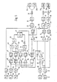
- 10, 11, 12, 13 indicate speed sensors for the front left wheel VL, the front right wheel VR, the rear left wheel HL and the rear right wheel HR.
- This Brehuntergeber 10, 11, 12, 13 are and circuits for amplification and signal conditioning 14, 15, 16, 17 is closed.
- the signals corresponding to the front wheels VL and VR are fed to a circuit for minimum value selection 18, the output of which is connected via a sample-and-hold stage 54 to an input of a comparator 19.
- the signals corresponding to the rear wheels HL and HR are connected to input resistors 20, 21 of an operational amplifier 22, which is fed back with a resistor 23.
- the output of the operational amplifier 22 is connected to the other input of the comparator 19.
- the outputs of the AND gates 48, 49 are connected to an OR gate 50 and the outputs of the threshold value stages 45, 47 are connected to a further OR gate 51 with an inverter 52 which has been resharpened.
- the OR gate 50 leads to the set input and the inverter 52 to the reset input a flip-flop 53, the non-inverted output of which controls the sample-and-hold stage 54, which is arranged between the minimum value selection 18 and the comparator 19.
- the non-inverted output of the flip-flop 53 leads to an inverter 55, the output of which leads to the inputs of the AND gates 56, 57.
- the signals corresponding to the speeds of the left front wheel VL or the right front wheel VR are processed in the circuit for the minimum value selection 18 in such a way that the speed signal which corresponds to the slower rotating wheel is passed. This signal is the best approximation of the actual driving speed of the motor vehicle.
- the speed signals of the left rear wheel HL and the right rear wheel HR are processed in the operational amplifier 22, namely by appropriately dimensioning the resistor 20, 21, 23 in such a way that a signal arises at the output of the operational amplifier 22 which corresponds to the arithmetic mean of the rear wheel speed, that is an average rear axle speed.
- This average rear axle speed is compared in the comparator 19 with the speed of the slowest rotating front wheel, ie approximately the driving speed.
- the one input of the AND gate 25 is driven, the other input of which is driven when the engine speed n M is above one predetermined threshold, which is defined by the threshold level 27. This is preferably the case when the engine speed is above the idling speed. Since this will generally be the case in the driving mode of the motor vehicle, the AND gate 25 is released at the upper input and the output signal of the threshold value stage 24 reaches the actuator 29 via the amplifier 28 and influences the drive machine via the fuel supply or the ignition or the like in its torque until the output signal of the comparator 19 falls below the value specified in the threshold 24.
- the actuator 29 is activated immediately and the engine torque is reduced until the driven rear wheels turn a certain amount faster than the slowest undriven front wheel .
- this difference is due to the threshold level 24 and corresponds to the optimal slip when starting off.
- the output of operational amplifier 22 is connected to comparators 30, 34, in which the average rear axle speed is compared with the speeds of the individual wheels.
- the speeds of the rear wheels HL, HR can differ considerably under certain circumstances because of the rear axle differential, for example when one wheel is on a dry surface and the other wheel is on an ice plate. In this case the wheel on the ice plate will spin and the wheel standing on a dry surface will stop so that the vehicle cannot start.
- this deviation from the average rear axle speed is recognized and results in the brake of the faster rotating wheel, in the example mentioned, that of the wheel on the ice plate, being applied. Since the wheel standing on a dry surface is not braked, starting with such a situation is possible with a device according to the invention.
- sample-and-hold stage 54 thus effects an extrapolation of the assumed driving speed, so that no false reaction can occur due to the fact that the front wheels which have come into the aquaplaning state simulate an incorrect driving speed. It understands It further becomes clear that the sample-and-hold stage 54 can be represented by various circuits known per se, in the simplest case by a discharge capacitor.
- the further embodiment of the invention provides for the actuation of the actuators 33, 37 to be blocked via the AND gates 56, 57 which are supplied with an O signal at their one inputs when the flip-flop 53 is set via the inverter 55, so that the output signals of the threshold value stages 31, 35 are not passed on.
Landscapes
- Engineering & Computer Science (AREA)
- Chemical & Material Sciences (AREA)
- Combustion & Propulsion (AREA)
- Transportation (AREA)
- Mechanical Engineering (AREA)
- Control Of Vehicle Engines Or Engines For Specific Uses (AREA)
- Regulating Braking Force (AREA)
- Control Of Driving Devices And Active Controlling Of Vehicle (AREA)
Applications Claiming Priority (4)
| Application Number | Priority Date | Filing Date | Title |
|---|---|---|---|
| DE3117104 | 1981-04-30 | ||
| DE3117104 | 1981-04-30 | ||
| DE3205627 | 1982-02-17 | ||
| DE19823205627 DE3205627A1 (de) | 1981-04-30 | 1982-02-17 | Antriebsschlupfregelung |
Related Parent Applications (1)
| Application Number | Title | Priority Date | Filing Date |
|---|---|---|---|
| EP82103596.1 Division | 1982-04-28 |
Publications (3)
| Publication Number | Publication Date |
|---|---|
| EP0280879A2 true EP0280879A2 (fr) | 1988-09-07 |
| EP0280879A3 EP0280879A3 (en) | 1988-10-12 |
| EP0280879B1 EP0280879B1 (fr) | 1990-07-25 |
Family
ID=25792957
Family Applications (2)
| Application Number | Title | Priority Date | Filing Date |
|---|---|---|---|
| EP88101288A Expired - Lifetime EP0280879B1 (fr) | 1981-04-30 | 1982-04-28 | Régulation du patinage d'entraînement |
| EP82103596A Expired EP0064669B1 (fr) | 1981-04-30 | 1982-04-28 | Régulation du patinage d'entraînement |
Family Applications After (1)
| Application Number | Title | Priority Date | Filing Date |
|---|---|---|---|
| EP82103596A Expired EP0064669B1 (fr) | 1981-04-30 | 1982-04-28 | Régulation du patinage d'entraînement |
Country Status (2)
| Country | Link |
|---|---|
| EP (2) | EP0280879B1 (fr) |
| DE (3) | DE3205627A1 (fr) |
Families Citing this family (35)
| Publication number | Priority date | Publication date | Assignee | Title |
|---|---|---|---|---|
| EP0128583B1 (fr) * | 1983-06-14 | 1988-12-14 | Robert Bosch Gmbh | Véhicule à traction sur les quatre roues |
| DE3416292A1 (de) * | 1984-05-03 | 1985-11-07 | Bosch Gmbh Robert | Regelschaltung fuer die angetriebenen raeder eines fahrzeugs |
| DE3417089A1 (de) * | 1984-05-09 | 1985-11-14 | Robert Bosch Gmbh, 7000 Stuttgart | Vortriebsregeleinrichtung |
| JPS6160331A (ja) * | 1984-09-03 | 1986-03-28 | Toyota Motor Corp | 車両スリツプ制御装置 |
| DE3586868T2 (de) * | 1984-09-21 | 1993-06-17 | Toyota Motor Co Ltd | Radschlupfregelsystem fuer ein fahrzeug. |
| EP0176785B1 (fr) * | 1984-09-28 | 1992-12-02 | Toyota Jidosha Kabushiki Kaisha | Système de réglage de glissage des roues |
| DE3435869A1 (de) * | 1984-09-29 | 1986-04-10 | Robert Bosch Gmbh, 7000 Stuttgart | Antriebsschlupfregelsystem |
| JPS61108040A (ja) * | 1984-10-30 | 1986-05-26 | Toyota Motor Corp | 車輪スリツプ制御装置 |
| JPH0626945B2 (ja) * | 1984-10-30 | 1994-04-13 | トヨタ自動車株式会社 | 車両用スリツプ制御装置 |
| US4757870A (en) * | 1985-02-20 | 1988-07-19 | Nissan Motor Co., Ltd. | Four wheel drive system having driving force distribution control responsive to front and rear wheel speed difference |
| DE3508879A1 (de) * | 1985-03-13 | 1986-09-25 | Zahnräderfabrik Renk AG, 8900 Augsburg | Steuerschaltung fuer kraftfahrzeuge |
| US4765430A (en) * | 1985-10-24 | 1988-08-23 | Volkswagen Ag | Method and arrangement for propulsion regulation of an automobile |
| DE3635095A1 (de) * | 1985-10-24 | 1987-04-30 | Volkswagen Ag | Verfahren und einrichtung zur vortriebsregelung eines kraftfahrzeugs im sinne des verhinderns eines unerwuenschten durchdrehens der angetriebenen fahrzeugraeder |
| DE3540708A1 (de) * | 1985-11-16 | 1987-05-21 | Bosch Gmbh Robert | Antriebsschlupfregelsystem |
| JP2545810B2 (ja) * | 1986-10-27 | 1996-10-23 | トヨタ自動車株式会社 | 車両の加速スリツプ制御装置 |
| JPS63112254A (ja) * | 1986-10-30 | 1988-05-17 | Sumitomo Electric Ind Ltd | 車輪スピン制御装置 |
| SE466143B (sv) * | 1987-04-17 | 1992-01-07 | Honda Motor Co Ltd | Traktionsregleranordning foer fordon |
| DE3883875T2 (de) * | 1987-06-11 | 1994-01-05 | Honda Motor Co Ltd | Antriebsrad-Schlupfsteuersystem für Fahrzeuge. |
| JPH0790715B2 (ja) * | 1987-09-29 | 1995-10-04 | 日産自動車株式会社 | 差動制限力制御装置 |
| JPH0725249B2 (ja) * | 1987-10-02 | 1995-03-22 | 日産自動車株式会社 | ロール剛性・差動制限力総合制御装置 |
| JP2527204B2 (ja) * | 1987-10-09 | 1996-08-21 | 日産自動車株式会社 | 四輪駆動車の駆動力配分制御装置 |
| DE3740433A1 (de) * | 1987-11-28 | 1989-06-08 | Bayerische Motoren Werke Ag | Regeleinrichtung zur regelung des antriebsdrehmomentes einer brennkraftmaschine eines kraftfahrzeuges |
| JP2528485B2 (ja) * | 1987-11-30 | 1996-08-28 | 日産自動車株式会社 | 四輪駆動車の駆動力配分制御装置 |
| JP2519960B2 (ja) * | 1987-12-28 | 1996-07-31 | いすゞ自動車株式会社 | 車両のトラクション制御方法 |
| DE3801323A1 (de) * | 1988-01-19 | 1989-07-27 | Bosch Gmbh Robert | Antriebsschlupfregelsystem |
| JP2688906B2 (ja) * | 1988-01-22 | 1997-12-10 | 曙ブレーキ工業株式会社 | 車両用トラクション制御方法および装置 |
| DE3811214C2 (de) * | 1988-04-02 | 1994-04-21 | Porsche Ag | Anordnung zur Steuerung der Kraftübertragung auf wenigstens zwei Achsen eines Kraftfahrzeuges |
| DE3833588A1 (de) * | 1988-10-03 | 1990-04-05 | Daimler Benz Ag | Antriebsschlupfregeleinrichtung fuer kraftfahrzeuge |
| DE3914364C2 (de) * | 1989-04-29 | 1998-04-09 | Teves Gmbh Alfred | Verfahren und Vorrichtung für Kraftfahrzeuge mit Ottomotoren zur Blockierschutz- oder Antriebsschlupfregelung |
| JPH03284429A (ja) * | 1990-03-30 | 1991-12-16 | Mazda Motor Corp | 車両のスリップ制御装置 |
| DE4103635A1 (de) * | 1991-02-07 | 1992-08-13 | Bosch Gmbh Robert | Antiblockierregelsystem |
| DE4141931C2 (de) * | 1991-12-19 | 2003-03-20 | Bosch Gmbh Robert | Vorrichtung zur Erzeugung eines Signals zur Ansteuerung eines Fahrwerkregelungssystems |
| US5742507A (en) | 1994-11-25 | 1998-04-21 | Itt Automotive Europe Gmbh | Driving stability control circuit with speed-dependent change of the vehicle model |
| DE10043413B4 (de) * | 1999-10-19 | 2010-08-05 | Luk Lamellen Und Kupplungsbau Beteiligungs Kg | Kraftfahrzeug |
| DE10114040B4 (de) * | 2000-04-04 | 2011-06-16 | Robert Bosch Gmbh | Verfahren und Vorrichtung zur Steuerung der Antriebseinheit eines Fahrzeugs |
Family Cites Families (3)
| Publication number | Priority date | Publication date | Assignee | Title |
|---|---|---|---|---|
| US3680655A (en) * | 1970-07-06 | 1972-08-01 | Gen Motors Corp | Electrical wheel slip limiting apparatus |
| US4042059A (en) * | 1973-05-21 | 1977-08-16 | Kelsey-Hayes Company | Anti-spin control system |
| US3938611A (en) * | 1973-11-23 | 1976-02-17 | Kelsey-Hayes Company | Intake manifold valve throttle control for spin control system |
-
1982
- 1982-02-17 DE DE19823205627 patent/DE3205627A1/de not_active Withdrawn
- 1982-04-28 EP EP88101288A patent/EP0280879B1/fr not_active Expired - Lifetime
- 1982-04-28 DE DE8888101288T patent/DE3280221D1/de not_active Expired - Lifetime
- 1982-04-28 EP EP82103596A patent/EP0064669B1/fr not_active Expired
- 1982-04-28 DE DE8282103596T patent/DE3279175D1/de not_active Expired
Also Published As
| Publication number | Publication date |
|---|---|
| EP0064669B1 (fr) | 1988-11-02 |
| DE3205627A1 (de) | 1982-11-18 |
| EP0280879B1 (fr) | 1990-07-25 |
| EP0064669A2 (fr) | 1982-11-17 |
| DE3280221D1 (de) | 1990-08-30 |
| DE3279175D1 (en) | 1988-12-08 |
| EP0064669A3 (en) | 1986-02-19 |
| EP0280879A3 (en) | 1988-10-12 |
Similar Documents
| Publication | Publication Date | Title |
|---|---|---|
| EP0280879B1 (fr) | Régulation du patinage d'entraînement | |
| AT390416B (de) | Anordnung zum verhindern des durchdrehens eines oder mehrerer angetriebener raeder, insbesondere beim anfahren | |
| DE3586923T2 (de) | Radschlupfregelsystem fuer ein fahrzeug. | |
| EP0163941B1 (fr) | Circuit de régulation pour les roues motrices d'un véhicule | |
| DE2851107C2 (de) | Schaltungsanordnung zur Verbesserung der Fahrstabilität von mit blockiergeschützten Bremsanlagen ausgerüsteten Fahrzeugen | |
| DE3883128T2 (de) | Steuervorrichtung für die Motorbremse. | |
| DE3545652A1 (de) | Einrichtung zur vortriebsregelung an kraftfahrzeugen | |
| DE3831105C1 (fr) | ||
| EP0892732B1 (fr) | Procede et dispositif permettant de commander la repartition de la force de freinage d'un vehicule automobile | |
| DE68920447T2 (de) | Antiblockiersteuerungssystem für Kraftfahrzeuge. | |
| DE2914165C2 (de) | Anordnung zum Verhindern des Durchdrehens einer oder mehrerer angetriebener Räder eines Fahrzeugs | |
| DE4006198C2 (de) | Antiblockier-Regelsystem für Kraftfahrzeuge | |
| DE2319862A1 (de) | Blockierschutzanlage fuer einzelradregelung | |
| DE3527959A1 (de) | Verfahren und vorrichtung zur vortriebsregelung | |
| DE2702800C2 (de) | Sicherheitsschaltung für Antiblockierregeleinrichtungen von Kraftfahrzeugen, insbesondere Straßenfahrzeugen | |
| DE19511162A1 (de) | Bremssystem für ein Kraftfahrzeug | |
| DE3546571C2 (fr) | ||
| DE69402642T2 (de) | Kraftfahrzeug-Bremsanordnung vom ABS-Typ | |
| DE3644134C2 (fr) | ||
| DE2717457A1 (de) | Verfahren und schaltungsanordnung zum regeln des bremsdruckes fuer fahrzeuge mit blockierschutz-regeleinrichtungen | |
| EP0452441B1 (fr) | Dispositif de freinage hydraulique destine a eviter des valeurs elevees de patinage au freinage ou a l'entrainement | |
| DE3644263C2 (de) | Antiblockiersystem für Kraftfahrzeuge | |
| DE4424318C2 (de) | Antriebsschlupfregelsystem | |
| DE19848209A1 (de) | Verfahren und Vorrichtung zum Halten eines Kraftfahrzeugs unter einer darauf wirkenden Kraft | |
| DE3627548A1 (de) | Kraftfahrzeug mit einer einrichtung zur einhaltung stabiler fahrzustaende |
Legal Events
| Date | Code | Title | Description |
|---|---|---|---|
| PUAI | Public reference made under article 153(3) epc to a published international application that has entered the european phase |
Free format text: ORIGINAL CODE: 0009012 |
|
| PUAL | Search report despatched |
Free format text: ORIGINAL CODE: 0009013 |
|
| 17P | Request for examination filed |
Effective date: 19880129 |
|
| AC | Divisional application: reference to earlier application |
Ref document number: 64669 Country of ref document: EP |
|
| AK | Designated contracting states |
Kind code of ref document: A2 Designated state(s): DE FR GB |
|
| AK | Designated contracting states |
Kind code of ref document: A3 Designated state(s): DE FR GB |
|
| 17Q | First examination report despatched |
Effective date: 19890414 |
|
| GRAA | (expected) grant |
Free format text: ORIGINAL CODE: 0009210 |
|
| AC | Divisional application: reference to earlier application |
Ref document number: 64669 Country of ref document: EP |
|
| AK | Designated contracting states |
Kind code of ref document: B1 Designated state(s): DE FR GB |
|
| GBT | Gb: translation of ep patent filed (gb section 77(6)(a)/1977) | ||
| REF | Corresponds to: |
Ref document number: 3280221 Country of ref document: DE Date of ref document: 19900830 |
|
| ET | Fr: translation filed | ||
| PLBE | No opposition filed within time limit |
Free format text: ORIGINAL CODE: 0009261 |
|
| STAA | Information on the status of an ep patent application or granted ep patent |
Free format text: STATUS: NO OPPOSITION FILED WITHIN TIME LIMIT |
|
| 26N | No opposition filed | ||
| PGFP | Annual fee paid to national office [announced via postgrant information from national office to epo] |
Ref country code: DE Payment date: 19940628 Year of fee payment: 13 |
|
| PGFP | Annual fee paid to national office [announced via postgrant information from national office to epo] |
Ref country code: GB Payment date: 19950407 Year of fee payment: 14 |
|
| PGFP | Annual fee paid to national office [announced via postgrant information from national office to epo] |
Ref country code: FR Payment date: 19950413 Year of fee payment: 14 |
|
| PG25 | Lapsed in a contracting state [announced via postgrant information from national office to epo] |
Ref country code: DE Effective date: 19960103 |
|
| PG25 | Lapsed in a contracting state [announced via postgrant information from national office to epo] |
Ref country code: GB Effective date: 19960428 |
|
| GBPC | Gb: european patent ceased through non-payment of renewal fee |
Effective date: 19960428 |
|
| PG25 | Lapsed in a contracting state [announced via postgrant information from national office to epo] |
Ref country code: FR Effective date: 19961227 |
|
| REG | Reference to a national code |
Ref country code: FR Ref legal event code: ST |