EP0280888A1 - Compensateur hydraulique de jeu pour la commande de soupapes des moteurs à combustion interne - Google Patents
Compensateur hydraulique de jeu pour la commande de soupapes des moteurs à combustion interne Download PDFInfo
- Publication number
- EP0280888A1 EP0280888A1 EP88101424A EP88101424A EP0280888A1 EP 0280888 A1 EP0280888 A1 EP 0280888A1 EP 88101424 A EP88101424 A EP 88101424A EP 88101424 A EP88101424 A EP 88101424A EP 0280888 A1 EP0280888 A1 EP 0280888A1
- Authority
- EP
- European Patent Office
- Prior art keywords
- element according
- compensation element
- bore
- clearance compensation
- central
- Prior art date
- Legal status (The legal status is an assumption and is not a legal conclusion. Google has not performed a legal analysis and makes no representation as to the accuracy of the status listed.)
- Granted
Links
- 238000002485 combustion reaction Methods 0.000 title claims 2
- 239000002184 metal Substances 0.000 claims description 8
- 239000011324 bead Substances 0.000 claims description 4
- 238000003780 insertion Methods 0.000 claims description 2
- 230000037431 insertion Effects 0.000 claims description 2
- 239000002991 molded plastic Substances 0.000 claims 1
- 210000002105 tongue Anatomy 0.000 claims 1
- 238000004519 manufacturing process Methods 0.000 abstract description 2
- 230000002093 peripheral effect Effects 0.000 description 3
- 238000009434 installation Methods 0.000 description 1
- 239000000725 suspension Substances 0.000 description 1
Images


Classifications
-
- F—MECHANICAL ENGINEERING; LIGHTING; HEATING; WEAPONS; BLASTING
- F01—MACHINES OR ENGINES IN GENERAL; ENGINE PLANTS IN GENERAL; STEAM ENGINES
- F01L—CYCLICALLY OPERATING VALVES FOR MACHINES OR ENGINES
- F01L1/00—Valve-gear or valve arrangements, e.g. lift-valve gear
- F01L1/20—Adjusting or compensating clearance
- F01L1/22—Adjusting or compensating clearance automatically, e.g. mechanically
- F01L1/24—Adjusting or compensating clearance automatically, e.g. mechanically by fluid means, e.g. hydraulically
- F01L1/2411—Adjusting or compensating clearance automatically, e.g. mechanically by fluid means, e.g. hydraulically by means of a hydraulic adjusting device located between the valve stem and rocker arm
Definitions
- the invention relates to a hydraulic lash adjuster according to the preamble of claim 1.
- Such play compensation elements are arranged, for example, in bores of rocker arms.
- the bore in the rocker arm is designed as a continuous bore in which a disc is arranged, which is supported, for example, against a snap ring and which in turn serves as a support for the hydraulic play compensation element.
- the disk has depressions in its surface that cooperates with the play compensation element, which allow oil to pass from the outside into the interior of the inner piston.
- the invention has for its object to create a mounting unit consisting of the hydraulic lash adjuster on the one hand and the disc on the other hand with the simplest technical means and thus eliminate assembly errors.
- the invention solves this problem in that the disk engages in the bore of the inner piston with radially resilient clamping projections when it contacts the end of the inner piston facing away from the pressure chamber. In this way, a non-positive connection between the hydraulic lash adjuster and the disc is achieved.
- a circumferential groove can be provided in the bore of the inner piston, into which the clamping projections engage, whereby a positive connection is established.
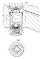
- a hydraulic lash adjuster 1 is mounted in a bore 2 of a rocker arm 3.
- the hydraulic lash adjuster 1 consists of an outer piston 4 which is closed at one end and which in a longitudinal bore with little play longitudinally displaceably receives the inner piston 5.
- the two pistons 4 and 5 enclose between them the high-pressure chamber 6, which is connected to the oil reservoir 8 provided in the inner piston 5 by a check valve 7 arranged in the inner piston 5.
- the hydraulic lash adjuster is supported with its end facing away from the high-pressure chamber 6 on a disk 9 which is inserted into the bore 2 and in turn is supported there against a snap ring 10.
- the disk 9 has, on its surface facing the hydraulic lash adjuster 1, recesses 11 which allow oil to pass into the oil reservoir 8.
- the oil supply to the hydraulic lash adjuster 1 takes place via the oil hole 12 in the rocker arm 3.
- the disc 9 has a central bore 13, into which the central pin 14 of a plastic part is inserted, which has clamping projections 15 which engage under radial prestress in the bore 16 of the inner piston 5 and thereby fix the disc 9 to the hydraulic play compensation element 1.
- the adhesion of the disk can be improved by the fact that the clamping projections 15 engage in a circumferential groove 17 of the bore 16.
- the clamping projections 15 are designed as a plurality of spring pulls which are distributed over the circumference and are curved radially outwards.
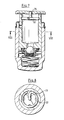
- the clamping projection is formed by a bead 18 which projects radially outwardly from a circumferential rim 19 which is connected by a plurality of spokes 20 to a central hub 21 which in turn carries the central pin 14, which in turn is inserted into the central bore 13 of the disk 9.
- FIGS. 5 and 6 differs from the previous one essentially only in that the bead 18 extends only over part of the peripheral regions lying between two successive spokes.
- a clamping projection is formed by a wire ring 22 which is open at a circumferential point and which at its one open end merges into a radially inwardly directed spoke 23 to which the axially extending central one is located Pin 24 connects.
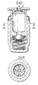
- the additional component is in the form of a sheet metal part which, starting from a central plate 25, is enlarged in diameter in two successive stages 26 and 27 and ends in a circumferential ring 28 with a projecting collar 29.
- the sheet metal part is provided with openings 30 at several peripheral points in the area between the central plate 25 and the peripheral ring 28.
- the sheet metal part is attached to the disk 9 by an additional rivet 31 which is inserted into a bore in the central plate 25 and is pressed into the central bore 13 of the disk 9.
- FIGS. 11 and 12 differs from the previous one in that the openings 32 also interrupt the collar 29.
- a collar 33 is provided for fastening the sheet metal part 4, which collar is put through directly from the central plate 25.
Landscapes
- Engineering & Computer Science (AREA)
- Mechanical Engineering (AREA)
- General Engineering & Computer Science (AREA)
- Valve-Gear Or Valve Arrangements (AREA)
- Valve Device For Special Equipments (AREA)
Applications Claiming Priority (2)
| Application Number | Priority Date | Filing Date | Title |
|---|---|---|---|
| DE3706006 | 1987-02-25 | ||
| DE19873706006 DE3706006A1 (de) | 1987-02-25 | 1987-02-25 | Hydraulisches spielausgleichselement fuer ventilsteuerungen an verbrennungsmotoren |
Publications (2)
| Publication Number | Publication Date |
|---|---|
| EP0280888A1 true EP0280888A1 (fr) | 1988-09-07 |
| EP0280888B1 EP0280888B1 (fr) | 1990-09-05 |
Family
ID=6321716
Family Applications (1)
| Application Number | Title | Priority Date | Filing Date |
|---|---|---|---|
| EP88101424A Expired - Lifetime EP0280888B1 (fr) | 1987-02-25 | 1988-02-02 | Compensateur hydraulique de jeu pour la commande de soupapes des moteurs à combustion interne |
Country Status (5)
| Country | Link |
|---|---|
| US (1) | US4800851A (fr) |
| EP (1) | EP0280888B1 (fr) |
| JP (1) | JPH0689657B2 (fr) |
| DE (2) | DE3706006A1 (fr) |
| ES (1) | ES2016997B3 (fr) |
Families Citing this family (11)
| Publication number | Priority date | Publication date | Assignee | Title |
|---|---|---|---|---|
| DE4030987A1 (de) * | 1990-10-01 | 1992-04-02 | Schaeffler Waelzlager Kg | Sich selbsttaetig hydraulisch einstellender ventilstoessel |
| DE4210143C2 (de) * | 1991-03-29 | 1994-02-24 | Fuji Heavy Ind Ltd | Ventilantrieb für eine Brennkraftmaschine |
| DE4494320C1 (de) * | 1993-06-18 | 1998-01-08 | Schaeffler Waelzlager Kg | Schlepphebel für die Betätigung von Gaswechselventilen |
| DE19503699A1 (de) * | 1995-02-04 | 1996-08-08 | Schaeffler Waelzlager Kg | Hydraulischer Ventiltriebsstößel |
| DE19610107A1 (de) * | 1996-03-15 | 1997-09-18 | Schaeffler Waelzlager Kg | Kipp- oder Schlepphebel mit einem Ventilspielausgleichselement |
| DE19629203B4 (de) * | 1996-07-19 | 2014-05-22 | Schaeffler Technologies Gmbh & Co. Kg | Hydraulische Spielausgleichsvorrichtung |
| DE19738811A1 (de) * | 1997-09-05 | 1999-03-11 | Schaeffler Waelzlager Ohg | Kipp- oder Schwinghebel für einen Ventiltrieb einer Brennkraftmaschine |
| DE19748162A1 (de) * | 1997-10-31 | 1999-05-06 | Audi Ag | Ventilbetätigungshebel mit einem hydraulischen Ventilspielausgleichselement |
| US6044813A (en) * | 1997-12-09 | 2000-04-04 | Siemens Automotive Corporation | Electromagnetic actuator with detached lower collar to align with cylinder head bore |
| WO2001020150A1 (fr) | 1999-09-17 | 2001-03-22 | Diesel Engine Retarders, Inc. | Accumulateur a volume captif pour systeme a perte de mouvement |
| DE102005059700A1 (de) * | 2005-12-14 | 2007-06-21 | Schaeffler Kg | Bauteil für einen Ventiltrieb einer Brennkraftmaschine |
Citations (2)
| Publication number | Priority date | Publication date | Assignee | Title |
|---|---|---|---|---|
| FR2370858A1 (fr) * | 1976-11-16 | 1978-06-09 | Motomak | Element de rattrapage de jeu hydraulique pour moteurs a combustion interne |
| FR2540554A1 (fr) * | 1983-02-09 | 1984-08-10 | Motomak | Element interieur pour element compensateur de jeu hydraulique de soupape, pour moteurs a combustion interne |
Family Cites Families (6)
| Publication number | Priority date | Publication date | Assignee | Title |
|---|---|---|---|---|
| JPH029046Y2 (fr) * | 1984-08-29 | 1990-03-06 | ||
| JPS6165209U (fr) * | 1984-10-04 | 1986-05-02 | ||
| DE3541198A1 (de) * | 1985-11-21 | 1987-05-27 | Motomak | Hydraulische spielausgleichsvorrichtung |
| DE3605645A1 (de) * | 1986-02-21 | 1987-08-27 | Motomak | Innenelement fuer ein hydraulisches ventilspielausgleichselement fuer verbrennungsmotoren |
| DE3606536A1 (de) * | 1986-02-28 | 1987-09-03 | Motomak | Innenelement fuer ein hydraulisches ventilspielausgleichselement fuer verbrennungsmotoren |
| DE3614258A1 (de) * | 1986-04-26 | 1987-10-29 | Motomak | Hydraulische ventilspielausgleichsvorrichtung fuer verbrennungsmotoren |
-
1987
- 1987-02-25 DE DE19873706006 patent/DE3706006A1/de not_active Withdrawn
-
1988
- 1988-02-02 EP EP88101424A patent/EP0280888B1/fr not_active Expired - Lifetime
- 1988-02-02 DE DE8888101424T patent/DE3860536D1/de not_active Expired - Lifetime
- 1988-02-02 ES ES88101424T patent/ES2016997B3/es not_active Expired - Lifetime
- 1988-02-05 US US07/152,540 patent/US4800851A/en not_active Expired - Fee Related
- 1988-02-22 JP JP63037695A patent/JPH0689657B2/ja not_active Expired - Lifetime
Patent Citations (2)
| Publication number | Priority date | Publication date | Assignee | Title |
|---|---|---|---|---|
| FR2370858A1 (fr) * | 1976-11-16 | 1978-06-09 | Motomak | Element de rattrapage de jeu hydraulique pour moteurs a combustion interne |
| FR2540554A1 (fr) * | 1983-02-09 | 1984-08-10 | Motomak | Element interieur pour element compensateur de jeu hydraulique de soupape, pour moteurs a combustion interne |
Also Published As
| Publication number | Publication date |
|---|---|
| JPS63227910A (ja) | 1988-09-22 |
| US4800851A (en) | 1989-01-31 |
| EP0280888B1 (fr) | 1990-09-05 |
| ES2016997B3 (es) | 1990-12-16 |
| DE3706006A1 (de) | 1988-09-08 |
| JPH0689657B2 (ja) | 1994-11-09 |
| DE3860536D1 (de) | 1990-10-11 |
Similar Documents
| Publication | Publication Date | Title |
|---|---|---|
| EP0223898B1 (fr) | Dispositif hydrauliquede compensation de jeu | |
| EP0301267B1 (fr) | Rotule située entre un culbuteur et une tige de soupape d'un moteur à combustion interne | |
| EP0244558B1 (fr) | Dispositif hydraulique de compensation du jeu des soupapes pour un moteur à combustion interne | |
| EP0280888B1 (fr) | Compensateur hydraulique de jeu pour la commande de soupapes des moteurs à combustion interne | |
| DE19742361A1 (de) | Elastischer Gelenkkörper | |
| DE10110914A1 (de) | Ventiltrieb einer Brennkraftmaschine mit einem schaltbaren rotationssymmetrischen Bauteil | |
| DE3438918A1 (de) | Mitnehmerverbindung zwischen einer welle und einer nabe | |
| EP1778988B1 (fr) | Joint spherique | |
| EP0745757A1 (fr) | Arbre à cames rapportées, en particulier pour moteurs à combustion interne | |
| DE8808443U1 (de) | Kugelgelenk | |
| EP0516962A1 (fr) | Poussoir de soupape mécanique pour moteurs à combustion interne | |
| DE3418804A1 (de) | Schutzmanschette fuer zylindrische teile, insbesondere fuer eine bolzenfuehrung einer teilbelag-scheibenbremse | |
| DE2535177C3 (de) | Gleitrolle | |
| DE19834677C2 (de) | Kugelgelenk, insbesondere für Lenk- und Achsgestänge von Kraftfahrzeugen | |
| DE4340035B4 (de) | Mechanischer Tassenstößel | |
| DE3519015C2 (de) | Ventilstößel für Verbrennungskraftmaschinen | |
| DE3823745A1 (de) | Schwungscheibe mit schwingungsdaempfer | |
| EP0380770A1 (fr) | Joint d'étanchéité pour tige de soupape | |
| DE2136844C3 (de) | Lagerung von Handschalthebeln für Kraftfahrzeuge | |
| DE4401011C2 (de) | Gebaute Nockenwelle | |
| EP0234343B1 (fr) | Elément interne pour élément hydraulique de compensation de jeu pour moteurs à combustion interne | |
| DE19706441A1 (de) | Kipp- oder Schwinghebel für einen Ventiltrieb einer Brennkraftmaschine | |
| EP0235599B1 (fr) | Elément interne pour élément hydraulique de compensation de jeu pour moteurs à combustion interne | |
| EP0757162B1 (fr) | Poussoir en forme de godet pour moteur à combustion interne | |
| EP0234022B1 (fr) | Elément interne pour un élément hydraulique de compensation de jeu pour moteurs à combustion interne |
Legal Events
| Date | Code | Title | Description |
|---|---|---|---|
| PUAI | Public reference made under article 153(3) epc to a published international application that has entered the european phase |
Free format text: ORIGINAL CODE: 0009012 |
|
| 17P | Request for examination filed |
Effective date: 19880202 |
|
| AK | Designated contracting states |
Kind code of ref document: A1 Designated state(s): DE ES FR GB IT |
|
| 17Q | First examination report despatched |
Effective date: 19900221 |
|
| ITF | It: translation for a ep patent filed | ||
| GRAA | (expected) grant |
Free format text: ORIGINAL CODE: 0009210 |
|
| AK | Designated contracting states |
Kind code of ref document: B1 Designated state(s): DE ES FR GB IT |
|
| GBT | Gb: translation of ep patent filed (gb section 77(6)(a)/1977) | ||
| REF | Corresponds to: |
Ref document number: 3860536 Country of ref document: DE Date of ref document: 19901011 |
|
| ET | Fr: translation filed | ||
| PLBE | No opposition filed within time limit |
Free format text: ORIGINAL CODE: 0009261 |
|
| STAA | Information on the status of an ep patent application or granted ep patent |
Free format text: STATUS: NO OPPOSITION FILED WITHIN TIME LIMIT |
|
| 26N | No opposition filed | ||
| PGFP | Annual fee paid to national office [announced via postgrant information from national office to epo] |
Ref country code: ES Payment date: 19920211 Year of fee payment: 5 |
|
| ITTA | It: last paid annual fee | ||
| PGFP | Annual fee paid to national office [announced via postgrant information from national office to epo] |
Ref country code: GB Payment date: 19930125 Year of fee payment: 6 |
|
| PG25 | Lapsed in a contracting state [announced via postgrant information from national office to epo] |
Ref country code: ES Free format text: LAPSE BECAUSE OF NON-PAYMENT OF DUE FEES Effective date: 19930203 |
|
| PG25 | Lapsed in a contracting state [announced via postgrant information from national office to epo] |
Ref country code: GB Effective date: 19940202 |
|
| PGFP | Annual fee paid to national office [announced via postgrant information from national office to epo] |
Ref country code: FR Payment date: 19940204 Year of fee payment: 7 |
|
| GBPC | Gb: european patent ceased through non-payment of renewal fee |
Effective date: 19940202 |
|
| PG25 | Lapsed in a contracting state [announced via postgrant information from national office to epo] |
Ref country code: FR Effective date: 19951031 |
|
| REG | Reference to a national code |
Ref country code: FR Ref legal event code: ST |
|
| REG | Reference to a national code |
Ref country code: ES Ref legal event code: FD2A Effective date: 19990301 |
|
| PGFP | Annual fee paid to national office [announced via postgrant information from national office to epo] |
Ref country code: DE Payment date: 20010217 Year of fee payment: 14 |
|
| PG25 | Lapsed in a contracting state [announced via postgrant information from national office to epo] |
Ref country code: DE Free format text: LAPSE BECAUSE OF NON-PAYMENT OF DUE FEES Effective date: 20020903 |
|
| PG25 | Lapsed in a contracting state [announced via postgrant information from national office to epo] |
Ref country code: IT Free format text: LAPSE BECAUSE OF NON-PAYMENT OF DUE FEES;WARNING: LAPSES OF ITALIAN PATENTS WITH EFFECTIVE DATE BEFORE 2007 MAY HAVE OCCURRED AT ANY TIME BEFORE 2007. THE CORRECT EFFECTIVE DATE MAY BE DIFFERENT FROM THE ONE RECORDED. Effective date: 20050202 |