EP0280959B1 - Ouvre-boîtes, de préférence à moteur électrique - Google Patents
Ouvre-boîtes, de préférence à moteur électrique Download PDFInfo
- Publication number
- EP0280959B1 EP0280959B1 EP88102267A EP88102267A EP0280959B1 EP 0280959 B1 EP0280959 B1 EP 0280959B1 EP 88102267 A EP88102267 A EP 88102267A EP 88102267 A EP88102267 A EP 88102267A EP 0280959 B1 EP0280959 B1 EP 0280959B1
- Authority
- EP
- European Patent Office
- Prior art keywords
- cutting
- opener
- cutter
- knife
- distance
- Prior art date
- Legal status (The legal status is an assumption and is not a legal conclusion. Google has not performed a legal analysis and makes no representation as to the accuracy of the status listed.)
- Expired - Lifetime
Links
- 238000005520 cutting process Methods 0.000 claims abstract description 137
- 239000002184 metal Substances 0.000 claims description 2
- ATJFFYVFTNAWJD-UHFFFAOYSA-N Tin Chemical compound [Sn] ATJFFYVFTNAWJD-UHFFFAOYSA-N 0.000 description 4
- 238000000034 method Methods 0.000 description 3
- 238000003825 pressing Methods 0.000 description 3
- 230000006378 damage Effects 0.000 description 2
- 230000002093 peripheral effect Effects 0.000 description 2
- 229910000679 solder Inorganic materials 0.000 description 2
- 241000985128 Cladium mariscus Species 0.000 description 1
- 241001125046 Sardina pilchardus Species 0.000 description 1
- 239000011324 bead Substances 0.000 description 1
- 230000000694 effects Effects 0.000 description 1
- 238000005265 energy consumption Methods 0.000 description 1
- 235000013305 food Nutrition 0.000 description 1
- 239000000463 material Substances 0.000 description 1
- 238000011089 mechanical engineering Methods 0.000 description 1
- 238000000465 moulding Methods 0.000 description 1
- 235000019512 sardine Nutrition 0.000 description 1
- 230000007704 transition Effects 0.000 description 1
- 238000003466 welding Methods 0.000 description 1
Images


Classifications
-
- B—PERFORMING OPERATIONS; TRANSPORTING
- B67—OPENING, CLOSING OR CLEANING BOTTLES, JARS OR SIMILAR CONTAINERS; LIQUID HANDLING
- B67B—APPLYING CLOSURE MEMBERS TO BOTTLES JARS, OR SIMILAR CONTAINERS; OPENING CLOSED CONTAINERS
- B67B7/00—Hand- or power-operated devices for opening closed containers
- B67B7/30—Hand-operated cutting devices
-
- B—PERFORMING OPERATIONS; TRANSPORTING
- B67—OPENING, CLOSING OR CLEANING BOTTLES, JARS OR SIMILAR CONTAINERS; LIQUID HANDLING
- B67B—APPLYING CLOSURE MEMBERS TO BOTTLES JARS, OR SIMILAR CONTAINERS; OPENING CLOSED CONTAINERS
- B67B7/00—Hand- or power-operated devices for opening closed containers
- B67B7/38—Power-operated cutting devices
-
- B—PERFORMING OPERATIONS; TRANSPORTING
- B67—OPENING, CLOSING OR CLEANING BOTTLES, JARS OR SIMILAR CONTAINERS; LIQUID HANDLING
- B67B—APPLYING CLOSURE MEMBERS TO BOTTLES JARS, OR SIMILAR CONTAINERS; OPENING CLOSED CONTAINERS
- B67B7/00—Hand- or power-operated devices for opening closed containers
- B67B7/30—Hand-operated cutting devices
- B67B7/32—Hand-operated cutting devices propelled by rotary gears or wheels around periphery of container
Definitions
- the invention relates to a can opener for separating the lid from a can, with a drive, preferably electrically operated, with a transport wheel which can be driven by the drive and rotatably mounted on a housing and which grips under the flanged rim of the can from the outside at the point of engagement with a at a fixed distance from the transport wheel on the housing on an axis of rotation, above the lid, which can be pivoted from a starting position into a cutting position and which has a piercing tip and a cutting edge adjoining the piercing tip, on which a knife engages with the lid in the cutting position of the knife standing cutting point, wherein a first stop guiding the can against the cutting edge is formed on the housing, which is arranged in the direction of movement of the can behind the engagement point on the can opener.
- Such an electrically operated can opener is known from US-A-4,622,749.
- the knife is initially in a starting position (FIG. 19B), in which the can edge of a tin can formed by a flanged edge can be attached to the transport wheel.
- the knife is then pivoted in the direction of the cutting position until it initially lies with its piercing tip on the top of the lid of the can (FIG. 19C).
- the knife limits the radial inner wall of the can rim from the inside and the transport wheel, the radially outer wall of the flanging rim from the outside, so that the flanging rim is held in place laterally by the knife and the transport wheel, and thereby the can is firmly coupled to the can opener.
- the knife When the control element is swiveled further by hand, the knife is then biased against the cover by a leaf spring until the control element switches on the electrical switch and the electric motor turns the transport wheel and thus the Can starts moving.
- the piercing tip of the knife penetrates automatically due to the predetermined cutting geometry and the spring-loaded contact pressure of the knife on the lid.
- the knife rotates around the pivot formed on the operating element until it strikes the elongated hole formed on it on the pin protruding laterally on the actuating member. Due to the cutting process now starting, cutting forces are exerted on the knife by the can lid, which results in a clockwise torque acting on the knife. This torque is partially transferred to the leaf spring via the control element and from there to the transport wheel via the edge of the can. (Fig. 19E).
- the control element holds the switch in its switched-on position due to the torque acting on the pin and thus on the control element, and on the other hand, if the control element has actually been removed with effort, the knife can only be swung out of the cutting gap very difficult because the knife is stuck in the cutting gap.
- the object of the invention is therefore to provide a can opener in which each can can be removed at any time and in any cutting position from the can opener without any significant effort; handling the can opener should be particularly simple.
- This object is achieved in that the solder on the cutting edge through the cutting point at a distance, viewed in the direction of movement of the flanged edge, lies in front of the center of the axis of rotation of the knife and that the distance corresponds to at least half the distance between the cutting point and the piercing tip.
- the invention therefore makes it possible for the first time to pivot the knife out of the cutting gap without a hindrance and with little effort, with the lid not yet completely separated from the can.
- a hand-held tin can is swiveled around the second stop, the knife slides out of the cutting gap almost without friction and thus without any significant effort.
- the invention also has a particularly advantageous effect on hand-held can openers, because here too the knife or the lever connected to the knife does not have to be actuated additionally by the hand, which must already be holding the can opener anyway. With the other hand, the knife cannot be swiveled because it has to grip the can firmly and securely.
- the center point of the axis of rotation of the knife viewed in the direction of movement of the flanged edge, lies at a distance x behind the point of the cutting intervention that the resulting force is generated during the cutting process at the cutting point of the knife from the cutting forces acting there, through the axis of rotation of the knife.
- the position of the cutting edge according to the invention with respect to the axis of rotation of the knife also has the advantage that the knife is not held in the cutting position by a positive fit, but only by the frictional forces which occur on the cutting edge during the cutting process. If the cutting process is interrupted, these frictional forces can easily be overcome so that the knife can be pivoted back into its attachment position and the can opener can be removed from the can. The cutting process can thus also be interrupted before the cover is completely removed, which is desirable in many cases.
- the invention provides that a second stop is formed on the knife, which acts in the cutting position of the can opener from above on the flanged edge and that the second stop, seen in the direction of movement of the flanged edge, is formed in front of the piercing tip on the knife.
- the second stop on the knife is particularly simple when it is formed by a sheet metal which projects laterally on the knife on the side facing the transport wheel.
- the attachment of this second stop to the knife can be achieved, for example, by deforming the knife, by welding, screwing or similar fastening means known in mechanical engineering. But there is also the possibility of integrally molding the knife with the second stop, for example as a die-cast part. In order to enable simple operation of the knife from the front by hand, it is advantageous that the second stop protrudes laterally on both sides of the knife.
- a projection directed towards the flange edge is formed on the second stop.
- the projection can be designed as a bead, groove, knob, etc.
- the can opener according to the invention can achieve an advantageously low removal torque on the knife if the angle (a) of the cutting edge relative to the can lid to be removed is not more than 30 °, in particular in a range between 15 ° and 30 °. Particularly low torque have arisen at an angle of attack of 27.5 °.
- the pivoting of the knife out of the cutting gap is also particularly favored in that the distance between the center points of the transport wheel and the axis of rotation of the knife is in the range of 5 to 10 mm, preferably 6.5 mm, in the direction of movement of the flanged edge and if the distance is vertical to the direction of movement in the range of 15 to 30 mm, preferably 24 mm.
- An advantageously low swing-out force is further achieved according to the invention in that a guide surface is connected to the cutting edge of the knife on the back and a first separating surface on the front and in that both surfaces enclose an angle d which is between 70 ° and 85 °.
- the relatively large angle d ensures that the knife does not wedge in the cutting gap of the can lid when cutting, but rather strives to push the knife upwards out of the cutting gap. This reduces the torque when the knife swings out of the cutting gap.
- the cutting point seen in the direction of movement of the flanged edge, lies in front of the point of engagement and at the same time a separating surface is formed on the knife, guidance of the can is achieved so that it does not oscillate back and forth around the point of engagement.
- This measure also reduces the energy consumption of the can opener. Due to the relatively large angle, the first separating surface takes on the largest part of the cutting energy right at the beginning of the cutting process, the can lid essentially being torn open or cut more by the knife at the cutting point than is cut. Therefore, the cutting edge is not sharp, so that injuries when swinging out the knife are excluded.
- the second parting surface the angle of which is relatively small compared to the first parting surface, is therefore necessary so that in the second phase of the parting process, only the material on both sides of the cutting point is pressed away with as little energy expenditure as possible, which means that the knife swings out due to the well-widened cutting gap facilitated.
- An advantageous knife shape is further achieved according to the invention in that the first and second separating surfaces run to the piercing tip of the knife.
- the two separating surfaces thus taper from the inlet side of the can to the piercing tip of the cutting edge, which facilitates the piercing process and also the pivoting back of the knife into the starting position.
- a good guidance of the can rim and thus also the can on the can opener is advantageously ensured by the fact that in the cutting position the end faces which laterally delimit the cutting edge and the free area rest with their edge areas on the inner wall of the flange edge. This measure prevents that, seen in plan view of the tin, it does not swing back and forth during the cutting process around the point of engagement, so that a cut that is almost parallel to the flanged edge is created, so that when the knife is swung out, the cut structures of the lid and Do not stand in the way of the edge.
- FIGS. 1 to 4 To avoid repetitions, the same reference numerals have been used in FIGS. 1 to 4 for correspondingly identical components.
- the can opener shown in FIG. 1 consists of a housing 1 on which, at a distance from one another, an axis of rotation 13 of a knife 3 and a transport wheel 4, which can be pivoted from a starting position 20 (shown in broken lines) into a cutting position 28, are mounted.
- the transport wheel 4 is driven by a gearbox (not shown in the drawing) and an electric motor in the direction of rotation 40.
- a gearbox not shown in the drawing
- the knife 3 is in FIGS. 1 to 4 in its cutting position 28, in which its cutting edge 8 at the cutting point 9 cuts through the lid 10 in the immediate vicinity of the flange edge 6.
- the slightly downwardly bent edge of the separated cover 10 is designated 11.
- the cutting edge 8 has an angle of attack "a" of 27.5 ° in the cutting position 28 shown.
- the setting or cutting angle "a” is determined by the cutting edge 8 and formed by the horizontal shown in Figures 1 and 2, which simultaneously forms the cover 10.
- the exact pivoting position of the knife 3 in the cutting position 28 is determined by a second stop 15, which is attached to the inlet side 46 of the knife 3 and is designed as a stop plate, and which lies on the upper edge 35 of the flanged edge 6 in the cutting position 28.
- the position of the knife 3 can thereby be easily adapted to different heights of the flanged edge 6.
- the cutting edge 8 is adjoined at the top by a first separating surface 14 which, with the guide surface 30 formed on the rear of the knife 3 and running essentially parallel to the wall surface 48 of the housing 1, encloses the angle "d".
- the first parting surface 14 is followed by a second parting surface 21, which includes the angle "f" with the guide surface 30.
- the guide surface 30 lies in the cutting position 28 according to FIG. 3 on the inner wall 39 of the wall 5 and on the radially outer interface 59 of the cover 10.
- edges 49, 50 which arise at the transitions from the first separating surface 14 to the second separating surface 21 and at the second separating surface 21 to the front 31 of the knife 3, run parallel to the cutting edge 8.
- these edges 49 run , 50 not parallel to the cutting edge 8, but they approach the piercing tip 17 and cut it.
- the piercing tip 17 forms the point closest to the center 33 of the transport wheel 4 at the end of the cutting edge 8.
- the disk 22 is mounted on the drive shaft 25 driving the transport wheel 4.
- the drive shaft 25 penetrates the housing wall 51 via the bore 52 and is connected to the drive motor via a gear, not shown in the drawing.
- the transport wheel 4 is rotatably connected to the drive shaft 25.
- bracket 23 On the wall surface 48, there is a bracket 23 which overlaps the transport wheel 4 and is fastened to the housing 1.
- the U-shaped bracket 23 serves to support particularly low food cans 24, such as oil sardine cans.
- a bar 53 is formed below the bracket 23 on the wall surface 48, which serves to support high cans 24.
- the cutting edge 8 is followed in FIG. 1 by a free surface 16 towards the outlet side 48, which includes the angle "e” with the cutting edge 8.
- the cutting edge 8 is delimited on the inlet side 46 by the end face 18, which extends vertically upwards in the drawing.
- the two end faces 18, 19 run at a distance "y" from one another which is dimensioned so large that the inner wall 39 of the wall 5 bears against the sections 36, 37 designed as corners.
- the sections 36, 37 are rounded, but this is not shown in the drawing.
- the cutting point 9 lies to the left of the axis of rotation 26 of the transport wheel 4, while the piercing tip 17 in the cutting position 28 (see FIG. 1) extends approximately perpendicularly above the axis of rotation 26. Furthermore, it can be seen that the distance from the end face 18 to the axis of rotation 26 is smaller than the distance from the end face 19 to the axis of rotation 26. This arrangement was therefore chosen so that during the cutting process from the teeth 27 to the lower edge 43 of the engagement point 29 radially outer flanged edge 6 (FIG. 3) transmitted circumferential force U1, which exerts a torque rotating counterclockwise according to FIG.
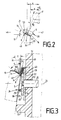
- FIG. 2 it can be seen that the cutting point 9 is arranged on the knife 3 to the left of the vertical straight line 34 running through the center 33 of the transport wheel 4.
- the solder L1 formed on the cutting edge 8, which cuts the cutting point 9, runs at a distance "b" in front of the center point 2 of the axis of rotation 13 of the knife 3. This strives for the cutting force acting perpendicularly on the cutting edge 8 at the cutting point 9, Swivel knife 3 clockwise. This endeavor is counteracted by the frictional forces acting on the cutting edge 8, so that the knife 3 is in practice moved counterclockwise during the cutting process, that is to say into the can 24.
- the control element can, for example, be a lift mounted on the housing 1, which is actuated by hand and serves on the one hand to pivot the knife 3 into the cutting position 28 and on the other hand serves to switch on the electric motor and thus the can opener, which is not shown in the drawing .
- Fig. 1 is further arranged on the housing 1 on the outlet side 47 a U-shaped handle 38 which facilitates the handling of the can opener.
- the operation of the can opener according to the invention is as follows: First of all, a can 24 is placed on the peripheral surface 45 of the transport wheel 4 with its lower edge 43 (FIG. 3) formed on the flanged edge 6 on the radially outer circumference. The flange 6 is now tied between the knife 3 and the transport wheel 4 in such a way that the can 24 can no longer be removed from the can opener.
- a torque acting counterclockwise on the knife 3 causes the piercing tip 17 to press with prestress on the top of the cover 10.
- the transport wheel 4 now begins to rotate in the direction of rotation 40 and thereby rotates the can 24 in the direction of movement 12. Because of the larger angle of attack "a" of the cutting edge 8 and the shifted point of application of the forces on the piercing tip 17, the piercing process is effected automatically and is required therefore no significant force from the control element.
- the knife 3 After inserting the cover 10, the knife 3 penetrates into the cover 10 through the cutting pressure and the cutting friction on its cutting edge 8 until the second stop 15 bears against the upper edge 35 of the flanged edge 6. Due to the predetermined cutting geometry, a resulting force "R” acts on the cutting point 9, which exerts a counterclockwise torque on the knife 3. This torque is supported in the form of the force "N” via the second stop 15 on the upper edge 35 of the flanged edge 6. As a result, the can 24 experiences a torque which rotates counterclockwise to the left in FIG. 1 and which in turn is supported on the transport wheel 4 and on the first stop 7. The greater the sheet thickness of the cover 10, the greater the force N and the more the flanged edge 6 is pressed against the transport wheel 4.
- This self-reinforcement always ensures that the transport of the can 24 and thus a continuous cutting process is ensured without the operator having to use additional force. Even when the distances from the upper edge 35 of the flanged edge 6 to the surface of the cover 10 differ, the knife 3 always adjusts itself automatically, so that the angle of attack "a" does not assume impermissible values.
- the flanged edge 6 is guided in the circumferential direction of the can 24 during the cutting process by the side surfaces 18, 19 of the knife 3 which are perpendicular to the direction of movement and face the flanged edge 6.
- the movement of the knife 3 into the starting position 20 is therefore only braked by the frictional engagement between the cover 10 and the flanged edge 6, which, however, can be easily overcome due to the first and second separating surfaces 14, 21 which are advantageous on the knife 3.
- the piercing tip 17 also does not hinder the pivoting out of the knife 3, since it does not touch the uncut area of the cover 10 either.
- the knife 3 can be swiveled out of the can 24 in the same way as described above.
Landscapes
- Engineering & Computer Science (AREA)
- Mechanical Engineering (AREA)
- Devices For Opening Bottles Or Cans (AREA)
- Constitution Of High-Frequency Heating (AREA)
- Discharge Heating (AREA)
Claims (15)
- Ouvre-boîtes destiné à séparer le couvercle (10) d'une boîte de conserve (24), avec un mécanisme d'entraînement, de préférence avec moteur électrique, avec une molette de transport (4), entraînée par le mécanisme d'entraînement, montée pivotante sur un boîtier (1), s'engageant extérieurement sous le collet serti (6) de la boîte de conserve (24) au point d'engrènement (29) pour assurer le transport, avec un couteau (3) monté sur un arbre de pivotement (13) à une distance fixe de la molette de transport (4), audessus du couvercle (10), pouvant basculer d'une position initiale (20) dans une position de coupe (28) et possédant une pointe de perforation (17) et une arête de coupe (8) prolongeant la pointe de perforation (17) qui, dans la position de coupe (28) du couteau (3), définit un point de coupe (9) par son engagement dans le couvercle (10), le boîtier (1) présentant une première butée (7) servant à guider la boîte de conserve (24) par rapport à l'arête de coupe (8) qui se trouve disposée après le point d'engrènement (29) de l'ouvre-boîtes, dans la direction de déplacement (12) de la boîte de conserve (24), caractérisé en ce que, lorsque l'on regarde dans la direction du déplacement (12) du collet serti (6), la perpendiculaire (L1) à l'arête de coupe (8) passant par le point de coupe (9) se trouve à une distance (b) en avant du centre (2) de l'arbre de pivotement (13) du couteau (3) et en ce que cette distance (b) est au moins égale à la moitié de la distance entre le point de coupe (9) et la pointe de perforation (17).
- Ouvre-boîtes selon la revendication 1, caractérisé en ce que l'on a la relation (b/c)øcot a > 1 entre la distance (b), la distance (c), mesurée verticalement entre le centre (2) de l'arbre de pivotement (13) du couteau (3), et l'angle de coupe (a) formé entre l'arête de coupe (8) et le couvercle (10) à sectionner.
- Ouvre-boîtes selon la revendication 2, caractérisé en ce que le centre (2) de l'arbre de pivotement (13) du couteau (3), vu dans la direction de déplacement (12) du collet serti (6), se trouve derrière le point d'engagement (9) de l'arête de coupe à une distance (x) telle que la force résultante (R) obtenue au point de coupe (9) du couteau (3) du fait des forces de coupe exercées dans l'opération de coupe passe par l'arbre de pivotement (13) du couteau (3).
- Ouvre-boîtes selon la revendication 1, caractérisé en ce qu'il existe un élément élastique entre l'organe de manoeuvre commandant l'entraînement électrique et le couteau (3).
- Ouvre-boîtes selon l'une des revendications précédentes, caractérisé en ce que le couteau (3) porte une seconde butée (15) qui, dans la position de coupe (28) de l'ouvre-boîtes, vient en appui par le haut sur le collet serti (6) et en ce que la seconde butée (15), vue dans la direction de déplacement (12) du collet serti (6), est formée sur le couteau (3) en avant de la pointe de perforation (17).
- Ouvre-boîtes selon la revendication 5, caractérisé en ce que la seconde butée (15) est formée par une tôle fixée sur le couteau (3) qui forme saillie latéralement sur le côté (31) du couteau (3) tourné vers la molette de transport (4).
- Ouvre-boîtes selon la revendication 6, caractérisé en ce qu'une saillie tournée vers le collet serti (6) est formée sur la seconde butée (15).
- Ouvre-boîtes selon la revendication 1, caractérisé en ce que l'arête de coupe (8) forme avec le couvercle (10) à sectionner un angle d'attaque (a) qui ne dépasse pas 30° et se situe en particulier entre 15° et 30°.
- Ouvre-boîtes selon la revendication 8, caractérisé en ce que l'angle d'attaque est de 27,5°.
- Ouvre-boîtes selon la revendication 1, caractérisé en ce que, dans la direction de déplacement (12) du collet serti (6), la distance entre les centres (33, 2) de la molette de transport (4) et de l'arbre de pivotement (13) du couteau (3) est entre 5 et 10 mm, de préférence de 6,5 mm et en ce que la distance, mesurée perpendiculairement à la direction de déplacement, est de l'ordre de 24 mm.
- Ouvre-boîtes selon la revendication 1, caractérisé en ce que l'arête de coupe (8) du couteau (3) se prolonge sur le côté arrière par une surface de guidage (30) et sur le côté avant (31) par une première surface de séparation (14) et en ce que les deux surfaces forment un angle (d) qui est compris entre 70° et 85°.
- Ouvre-boîtes selon la revendication 11, caractérisé en ce que la première surface de séparation (14) est prolongée par une seconde surface de séparation (21) qui forme avec la surface de guidage (30) un angle (f) qui est inférieur à l'angle (d).
- Ouvre-boîtes selon la revendication 12, caractérisé en ce que l'angle (d) est compris entre 40° et 65°.
- Ouvre-boîtes selon la revendication 10 ou 12, caractérisé en ce que la première et la seconde surfaces de séparation (14, 21) se rejoignent à la pointe de perforation (17) du couteau (3).
- Ouvre-boîtes selon la revendication 13, caractérisé en ce que, dans la position de coupe (28), les surfaces frontales (18, 19) délimitant latéralement l'arête de coupe (8) et la surface de dépouille (16) reposent par leurs bords (36, 37) sur la paroi intérieure (39) du collet serti (6).
Priority Applications (1)
| Application Number | Priority Date | Filing Date | Title |
|---|---|---|---|
| AT88102267T ATE65765T1 (de) | 1987-02-27 | 1988-02-17 | Dosenoeffner, vorzugsweise mit elektrischem antrieb. |
Applications Claiming Priority (4)
| Application Number | Priority Date | Filing Date | Title |
|---|---|---|---|
| DE3706414 | 1987-02-27 | ||
| DE3706414 | 1987-02-27 | ||
| DE3710884 | 1987-04-01 | ||
| DE3710884 | 1987-04-01 |
Publications (2)
| Publication Number | Publication Date |
|---|---|
| EP0280959A1 EP0280959A1 (fr) | 1988-09-07 |
| EP0280959B1 true EP0280959B1 (fr) | 1991-07-31 |
Family
ID=25852990
Family Applications (1)
| Application Number | Title | Priority Date | Filing Date |
|---|---|---|---|
| EP88102267A Expired - Lifetime EP0280959B1 (fr) | 1987-02-27 | 1988-02-17 | Ouvre-boîtes, de préférence à moteur électrique |
Country Status (7)
| Country | Link |
|---|---|
| US (1) | US4901441A (fr) |
| EP (1) | EP0280959B1 (fr) |
| KR (1) | KR910006137B1 (fr) |
| AT (1) | ATE65765T1 (fr) |
| CA (1) | CA1303839C (fr) |
| DE (1) | DE3863941D1 (fr) |
| ES (1) | ES2023225B3 (fr) |
Families Citing this family (3)
| Publication number | Priority date | Publication date | Assignee | Title |
|---|---|---|---|---|
| FR2669912B1 (fr) * | 1990-11-29 | 1993-07-30 | Moulinex Sa | Ouvre-boites. |
| US6516524B1 (en) | 2000-10-23 | 2003-02-11 | Hamilton Beach/Proctor-Silex, Inc. | Battery operated portable can opener |
| USD444686S1 (en) | 2000-10-23 | 2001-07-10 | Hamilton Beach/Proctor-Silex, Inc. | Can opener |
Family Cites Families (7)
| Publication number | Priority date | Publication date | Assignee | Title |
|---|---|---|---|---|
| US1863483A (en) * | 1927-10-03 | 1932-06-14 | Glenn L Jackson | Can opener |
| DE579192C (de) * | 1932-03-19 | 1933-06-22 | Grodetzky & Polak | Vorrichtung zum Aufschneiden, insbesondere von Konservenbuechsen |
| US2024449A (en) * | 1934-01-13 | 1935-12-17 | Ernest J Hileman | Can opener |
| US2975515A (en) * | 1959-12-21 | 1961-03-21 | Elvin S Land | Can opener |
| CH505024A (de) * | 1968-01-08 | 1971-03-31 | Metallindustrie Denkingen Gebr | Elektrisch betriebener Dosenöffner |
| US3706135A (en) * | 1969-11-08 | 1972-12-19 | Matsushita Electric Industrial Co Ltd | An electrically powered can opener |
| JPS60240693A (ja) * | 1984-05-07 | 1985-11-29 | 愛知電機株式会社 | 電気缶切機 |
-
1988
- 1988-02-17 ES ES88102267T patent/ES2023225B3/es not_active Expired - Lifetime
- 1988-02-17 AT AT88102267T patent/ATE65765T1/de not_active IP Right Cessation
- 1988-02-17 EP EP88102267A patent/EP0280959B1/fr not_active Expired - Lifetime
- 1988-02-17 DE DE8888102267T patent/DE3863941D1/de not_active Expired - Fee Related
- 1988-02-22 US US07/158,860 patent/US4901441A/en not_active Expired - Fee Related
- 1988-02-25 CA CA000559805A patent/CA1303839C/fr not_active Expired - Fee Related
- 1988-02-27 KR KR1019880002120A patent/KR910006137B1/ko not_active Expired
Also Published As
| Publication number | Publication date |
|---|---|
| CA1303839C (fr) | 1992-06-23 |
| KR910006137B1 (ko) | 1991-08-16 |
| ES2023225B3 (es) | 1992-01-01 |
| KR880012477A (ko) | 1988-11-26 |
| US4901441A (en) | 1990-02-20 |
| ATE65765T1 (de) | 1991-08-15 |
| DE3863941D1 (de) | 1991-09-05 |
| EP0280959A1 (fr) | 1988-09-07 |
Similar Documents
| Publication | Publication Date | Title |
|---|---|---|
| DE2915901A1 (de) | Einrichtung zum schneiden von papier mit einer rotierenden klinge | |
| DE1482641C3 (de) | Elektrischer Dosenöffner | |
| EP0509230A2 (fr) | Mécanisme d'avancement pour une machine de coupe pour couper des produits alimentaires | |
| DE4209530C1 (fr) | ||
| DE1933965A1 (de) | Allgemein verwendbares kraftbetriebenes Handwerkzeug | |
| DE2527634C3 (de) | Tragbare Schneidvorrichtung | |
| DE4416522A1 (de) | Papierbahn-Schneideeinrichtung | |
| EP0280959B1 (fr) | Ouvre-boîtes, de préférence à moteur électrique | |
| DE3415438A1 (de) | Eindrueckungsfreie rohrschneidevorrichtung | |
| DE69903687T2 (de) | Vorrichtung zum Bearbeiten eines Stanzmessers und Schneidmesser dafür | |
| DE3804855C2 (fr) | ||
| DE2615301B2 (de) | Zangenartiges Schneidinstrument | |
| EP3243617B1 (fr) | Decoupeuse | |
| DE2718793C3 (de) | Trommelschere | |
| DE2528208A1 (de) | Stabeisenschere | |
| DE2202199A1 (de) | Besaeumschere und Trennschere fuer Stahlbleche | |
| DE4312469C2 (de) | Schneidgerät für stangenförmige Werkstücke, insbesondere für laminiertes Flachband | |
| DE2632425C3 (de) | Maschine zum öffnen von Briefumschlägen | |
| EP3243616B1 (fr) | Decoupeuse | |
| DE74101C (de) | Büchsenöffner | |
| DE2706150C3 (de) | Schneidvorrichtung zum öffnen von quaderförmigen Packungen | |
| DE2717619C2 (de) | Schere zum Zerkleinern von insbesondere Altmaterialien | |
| EP1522444A2 (fr) | Dispositif manuel pour l'assemblage des joints d'étanchéité | |
| DE8706119U1 (de) | Von Hand betätigbarer Kabeltrenner | |
| DE569050C (de) | Blechschere mit Vorrichtung zum Abschraegen der Schnittkanten, welche ein Gestell und zwei Kreismesser aufweist |
Legal Events
| Date | Code | Title | Description |
|---|---|---|---|
| PUAI | Public reference made under article 153(3) epc to a published international application that has entered the european phase |
Free format text: ORIGINAL CODE: 0009012 |
|
| AK | Designated contracting states |
Kind code of ref document: A1 Designated state(s): AT CH DE ES FR GB IT LI NL SE |
|
| 17P | Request for examination filed |
Effective date: 19880926 |
|
| 17Q | First examination report despatched |
Effective date: 19900424 |
|
| GRAA | (expected) grant |
Free format text: ORIGINAL CODE: 0009210 |
|
| AK | Designated contracting states |
Kind code of ref document: B1 Designated state(s): AT CH DE ES FR GB IT LI NL SE |
|
| PG25 | Lapsed in a contracting state [announced via postgrant information from national office to epo] |
Ref country code: IT Free format text: LAPSE BECAUSE OF FAILURE TO SUBMIT A TRANSLATION OF THE DESCRIPTION OR TO PAY THE FEE WITHIN THE PRE;WARNING: LAPSES OF ITALIAN PATENTS WITH EFFECTIVE DATE BEFORE 2007 MAY HAVE OCCURRED AT ANY TIME BEFORE 2007. THE CORRECT EFFECTIVE DATE MAY BE DIFFERENT FROM THE ONE RECORDED.SCRIBED TIME-LIMIT Effective date: 19910731 Ref country code: NL Effective date: 19910731 Ref country code: SE Effective date: 19910731 |
|
| REF | Corresponds to: |
Ref document number: 65765 Country of ref document: AT Date of ref document: 19910815 Kind code of ref document: T |
|
| GBT | Gb: translation of ep patent filed (gb section 77(6)(a)/1977) | ||
| REF | Corresponds to: |
Ref document number: 3863941 Country of ref document: DE Date of ref document: 19910905 |
|
| ET | Fr: translation filed | ||
| REG | Reference to a national code |
Ref country code: ES Ref legal event code: FG2A Ref document number: 2023225 Country of ref document: ES Kind code of ref document: B3 |
|
| NLV1 | Nl: lapsed or annulled due to failure to fulfill the requirements of art. 29p and 29m of the patents act | ||
| PLBE | No opposition filed within time limit |
Free format text: ORIGINAL CODE: 0009261 |
|
| STAA | Information on the status of an ep patent application or granted ep patent |
Free format text: STATUS: NO OPPOSITION FILED WITHIN TIME LIMIT |
|
| 26N | No opposition filed | ||
| PGFP | Annual fee paid to national office [announced via postgrant information from national office to epo] |
Ref country code: GB Payment date: 19950130 Year of fee payment: 8 |
|
| PGFP | Annual fee paid to national office [announced via postgrant information from national office to epo] |
Ref country code: FR Payment date: 19950203 Year of fee payment: 8 |
|
| PGFP | Annual fee paid to national office [announced via postgrant information from national office to epo] |
Ref country code: AT Payment date: 19950213 Year of fee payment: 8 |
|
| PGFP | Annual fee paid to national office [announced via postgrant information from national office to epo] |
Ref country code: ES Payment date: 19950220 Year of fee payment: 8 |
|
| PGFP | Annual fee paid to national office [announced via postgrant information from national office to epo] |
Ref country code: DE Payment date: 19950223 Year of fee payment: 8 |
|
| PGFP | Annual fee paid to national office [announced via postgrant information from national office to epo] |
Ref country code: CH Payment date: 19950327 Year of fee payment: 8 |
|
| PG25 | Lapsed in a contracting state [announced via postgrant information from national office to epo] |
Ref country code: AT Effective date: 19960217 Ref country code: GB Effective date: 19960217 |
|
| PG25 | Lapsed in a contracting state [announced via postgrant information from national office to epo] |
Ref country code: ES Free format text: LAPSE BECAUSE OF NON-PAYMENT OF DUE FEES Effective date: 19960219 |
|
| PG25 | Lapsed in a contracting state [announced via postgrant information from national office to epo] |
Ref country code: CH Effective date: 19960229 Ref country code: LI Effective date: 19960229 |
|
| GBPC | Gb: european patent ceased through non-payment of renewal fee |
Effective date: 19960217 |
|
| REG | Reference to a national code |
Ref country code: CH Ref legal event code: PL |
|
| PG25 | Lapsed in a contracting state [announced via postgrant information from national office to epo] |
Ref country code: FR Effective date: 19961031 |
|
| PG25 | Lapsed in a contracting state [announced via postgrant information from national office to epo] |
Ref country code: DE Effective date: 19961101 |
|
| REG | Reference to a national code |
Ref country code: FR Ref legal event code: ST |
|
| REG | Reference to a national code |
Ref country code: ES Ref legal event code: FD2A Effective date: 19990201 |