EP0281152A2 - Procédé et appareil de contrôle de l'alimentation en essence d'un moteur à explosion - Google Patents
Procédé et appareil de contrôle de l'alimentation en essence d'un moteur à explosion Download PDFInfo
- Publication number
- EP0281152A2 EP0281152A2 EP88103381A EP88103381A EP0281152A2 EP 0281152 A2 EP0281152 A2 EP 0281152A2 EP 88103381 A EP88103381 A EP 88103381A EP 88103381 A EP88103381 A EP 88103381A EP 0281152 A2 EP0281152 A2 EP 0281152A2
- Authority
- EP
- European Patent Office
- Prior art keywords
- signal
- amount
- fuel supply
- air
- fuel
- Prior art date
- Legal status (The legal status is an assumption and is not a legal conclusion. Google has not performed a legal analysis and makes no representation as to the accuracy of the status listed.)
- Granted
Links
Images

Classifications
-
- F—MECHANICAL ENGINEERING; LIGHTING; HEATING; WEAPONS; BLASTING
- F02—COMBUSTION ENGINES; HOT-GAS OR COMBUSTION-PRODUCT ENGINE PLANTS
- F02D—CONTROLLING COMBUSTION ENGINES
- F02D41/00—Electrical control of supply of combustible mixture or its constituents
- F02D41/02—Circuit arrangements for generating control signals
- F02D41/04—Introducing corrections for particular operating conditions
-
- F—MECHANICAL ENGINEERING; LIGHTING; HEATING; WEAPONS; BLASTING
- F02—COMBUSTION ENGINES; HOT-GAS OR COMBUSTION-PRODUCT ENGINE PLANTS
- F02D—CONTROLLING COMBUSTION ENGINES
- F02D41/00—Electrical control of supply of combustible mixture or its constituents
- F02D41/02—Circuit arrangements for generating control signals
- F02D41/04—Introducing corrections for particular operating conditions
- F02D41/08—Introducing corrections for particular operating conditions for idling
- F02D41/083—Introducing corrections for particular operating conditions for idling taking into account engine load variation, e.g. air-conditionning
Definitions
- the present invention relates to a fuel supply control method and an apparatus for an internal combustion engine, more particularly to a control method and an apparatus capable of adequately controlling the increment of fuel mixture to be supplied so as to compensate the increase of load, which is required of the engine, when auxiliary equipment of a car, such as a car air conditioner, headlights, a power steering device and so on, operates.
- the control apparatus when a relatively large load is put on an engine during the idling state thereof, i.e., when a driver turns on a switch for operating a car air conditioner, for example, the control apparatus produces an actuating signal to a by-pass valve for supplying additional air for the engine by by-passing a throttle valve which is closed din the idling state.
- An actuating signal having a different value is stored in advance in a table within the control apparatus for every kind of load, and it is read out therefrom in response to a load required. Namely, an actuating signal produced by the control apparatus corresponds to a kind of auxiliary equipment required to operate. The opening degree of the by-pass valve is determined accordingly, and additional air is introduced into the engine through the by-pass valve.
- an amount of fuel to be increased in response to introduction of the additional air is also retrieved from another table within the control apparatus with the aforesaid actuating signal, and then fuel according to the retrieved amount is supplied for the engine, so that the fuel is increased commensurately with the amount of the additional air.
- an output power of the engine is increased and hence the number of revolutions thereof is prevented from decreasing.
- the prior art control apparatus as described above has the following drawback.
- a switch for requiring auxiliary equipment to operate is turned on, the auxiliary equipment is actuated immediately, but fuel mixture, the flow rate of which is increased so as to compensate the increase of load caused by operation of the auxiliary equipment, reaches the engine behind time.
- a number of revolutions of the engine decreases temporarily, and the operational condition of the engine becomes unstable.
- An object of the present invention is to provide a fuel supply control method and an apparatus for an internal combustion engine, which can prevent a number of revolutions of the engine from temporarily decreasing, when auxiliary equipment of a car is required to operate.
- a feature of the present invention resides in that when auxiliary equipment is required to operate, the amounts of increments in fuel and air to be supplied for an engine are determined in response to a kind of the auxiliary equipment required to operate, the fuel and air supplied for the engine are increased in accordance with the determined incremental amounts thereof, and after an output power of the engine reaches a predetermined value, an actuating instruction is given to the auxiliary equipment.
- fuel increased in accordance with the determined increment thereof is at first supplied for an engine and then additional air is introduced in response to the determined increment of air.
- additional air is introduced in response to the determined increment of air.
- an actuating instruction is given to auxiliary equipment required to operate after a predetermined time from supply of the additional air for an engine. With this time duration, the engine can surely increase its output power sufficiently for being burdened with increased load. Especially, in the idling state of the engine, the actuating signal can be given to the auxiliary equipment when the number of revolutions of the engine reaches a predetermined value.
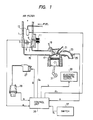
- a throttle valve 3 the opening of which is detected by a throttle sensor 5.
- the sensor 5 produces a signal ⁇ representative of the opening degree of the throttle valve 3.
- a by-pass 7 in such a manner that the throttle valve 3 is bridged from upstream to downstream.
- a by-pass valve 9 the opening of which is controlled by a solenoid coil 11 in response to an actuating signal S A applied thereto to control the amount of air flowing through the by-pass 7.
- the actuating signal S A is called an air increment signal, hereinafter.
- a fuel injector 13 is equipped upstream of the throttle valve 3, for which pressure-regulated fuel is supplied.
- a valve of the injector 13 is opened in accordance with a signal P F applied thereto to inject fuel into the throttle chamber 1.
- the signal P F is given in the form of the opening time duration of the valve of the injector 13, and the amount of fuel injected depends on the existing time duration of the signal P F , because the pressure of fuel supplied for the injector 13 is regulated constantly.
- the injected fuel is mixed with air supplied from an air filter (not shown).
- Air/fuel mixture is transported through an intake pipe 15 and introduced into a combustion chamber 17 when an inlet valve 19 is opened.
- the introduced mixture is burnt by an ignition spark plug 21, and exhaust gas is discharged through an exhaust pipe 23 when an outlet valve (not shown) is opened.
- an oxygen sensor 25 on the exhaust pipe 23, which detects the concentration of oxygen remaining in the exhaust gas and produces an A/F ratio signal R proportional to an air/fuel ratio of the fuel mixture supplied.
- High voltage applied to the ignition spark plug 21 is generated by an ignition coil 27 in response to a timing signal G and distributed by a distributor 29 to the ignition spark plug 21 of respective cylinders. From the distributor 29, a signal N proportional to a number of revolutions of the engine is also derived.
- the present invention is applied to an internal combustion engine of a so-called single point injection (SPI) type, in which a single injector is provided upstream of the throttle valve 3 and injects fuel for all cylinders.
- SPI single point injection
- the injection type is not confined to the SPI type, but may be in the form of another SPI type, in which there is provided a single injector downstream of a throttle valve, a multi-point injection (MPI) type, in which an injector is mounted on each branch pipe connected to each cylinder, or a division-type SPI, in which the intake system is divided into plural groups downstream of a throttle valve with a single injector allocated to each group.
- MPI multi-point injection
- a compressor (not shown) of the air conditioner is coupled with a crank shaft 31 through an electromagnetic clutch 33.
- the electromagnetic clutch 33 is energized in response to an actuating signal L applied thereto, torque being produced at the crank shaft 31 is transmitted to the compressor so that the air conditioner operates.
- the engine is burdened with load increased in correspondence to the power necessitated by the compressor.
- the control apparatus comprises a control unit 35 having a built-in microprocessor, which processes the opening degree signal ⁇ , the number-of-revolution signal N and the A/F ratio signal R sent from the respective sensors and outputs the ignition timing signal G, the air increment signal S A , the fuel supply signal P F and the actuating signal L.
- the microprocessor is constructed in the same manner as a microprocessor of this kind conventionally used. Namely, it has a central processing unit (CPU) for executing predetermined processing programs, a read-only memory (ROM) for storing the programs and various constants necessary for the processing operation in the CPU, and a random access memory (RAM) for temporarily storing signals detected by various sensors as described above, and variables necessary for and results in the processing operation in the CPU. There are further provided various input/output interface. These constituent elements are interconnected by known buses.
- CPU central processing unit
- ROM read-only memory
- RAM random access memory
- the control unit 35 is also supplied with a signal S L from a switch 37.
- the switch 37 is a switch for requiring a car air conditioner to operate, which is manipulated by a user when he wants to operate it.
- the control unit 35 determines the basic amount of fuel to be supplied for the engine on the basis of the opening degree signal ⁇ and the number-of-revolution signal N. There are various methods of determining the basic amount of fuel to be supplied.
- the thus determined basic amount of fuel to be supplied is corrected in accordance with the A/F ratio signal R to produce the fuel supply signal P F , by which an actual A/F ratio of the fuel mixture is maintained at a predetermined value. Further, as already described, the fuel supply signal P F is produced in the form of a time duration T i during which the valve of the injector 13 is opened.
- the method as described above in which the amount of fuel to be supplied is determined on the basis of the opening degree of the throttle valve and the number of revolutions of the engine, is called an ⁇ -N fuel control method, which is one of methods simpler than a well known Q a -N fuel control method, in which the amount of fuel to be supplied is determined on the basis of the amount Q a of suction air detected by an airflow sensor and the number N of revolutions of the engine.
- the method of determining the amount of fuel to be supplied is not confined to the ⁇ -N fuel control method as described above, but may be in the form of the Q a -N fuel control method.
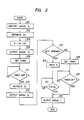
- control unit 35 which is characterized by the present invention, with reference to the flow chart of Fig. 2.
- a produced signal S L is identified in order to ascertain a kind of auxiliary equipment required to operate.
- an increment ⁇ T i of fuel corresponding to the identified signal S L is retrieved in a table at step 203. It is to be noted that in this flow chart the amount of fuel is represented in the form of a time duration T i or ⁇ T i in which the valve of the injector 13 is opened.
- a corrected amount T i ⁇ of fuel is obtained by adding the retrieved increment ⁇ T i to the amount T i already determined just before the signal S L occurs.
- the corrected amount T i ⁇ of fuel is output to the injector 13 as the fuel supply signal P F , whereby the injector 13 injects fuel of the amount corresponding to the signal P F .
- a timer which is included in the microprocessor and has a time constant T1 is set at step 209. It is judged at step 211 whether or not time T1 has lapsed. When time T1 has lapsed, the timer is made off to produce an output signal. After that, the air increment signal S A is retrieved in a table on the basis of the increment ⁇ T i of fuel obtained at step 203, and the signal S A is output to the solenoid coil 11 at step 215. The by-pass valve 9 is opened so that air of the amount according to the signal S A is introduced through the by-pass 7, in addition to air sucked through the throttle valve 3.
- the reason why there is provided a time difference T1 between the output of the signal P F and that of the signal S A is as follows.
- the delay in the transportation to the combustion chamber 17 is larger in fuel than in air. Namely, although air reaches the combustion chamber 17 in a short time after the valve 9 is opened, it takes longer time until the injected fuel reaches the combustion chamber 17. If, therefore, fuel is at first increased and at a predetermined time thereafter, in general several hundred milliseconds later, air is increased, then both reach the combustion chamber 17 almost at the same time, and therefore, it never occurs that the fuel mixture becomes too lean even temporarily.
- time T1 may be unnecessary, or sufficient with a very small value. In this manner, the provision of time T1 depends upon an engine, to which the present invention is applied.
- the operational condition of the engine is judged at step 217, i.e., it is judged whether or not the throttle valve 3 is in the idle opening.
- This judgement can be carried out by judging whether or not the value of the signal ⁇ is from the throttle sensor 5 is larger than a predetermined value. Further, it can also be judged by observing whether or not an idle switch, which is often equipped to a throttle valve and detects that the throttle valve is in the idle position, is operated.
- this fact means that the engine is in the idling state.
- the number N of revolutions of the engine is input at step 219 and it is judged at step 221 whether or not N is larger than a predetermined value N a . If N is equal to or larger than N a , the signal L is produced to the electromagnetic clutch 33 at step 223. If N is smaller than N a , then the production of the signal L is awaited until N reaches N a .
- step 217 if the throttle valve 3 is not in the idle opening, the engine is regarded as being operating at a certain number of revolutions larger than that of the idling state.
- another timer which is also included in the microprocessor and has a time constant T2, is set at step 225, and it is judged at step 227 whether or not time T2 has lapsed from the set of the timer. After the timer is made off, i.e., when time T2 has lapsed, the signal L is produced at step 223.
- Fig. 3a shows the changing manner of torque ⁇ produced by an engine and the number N of revolutions thereof, when the engine is controlled in accordance with the present invention. Further, those according to the prior art apparatus are shown in Fig. 3b for the purpose of the comparison.
- the invention apparatus has no recessed portion in the change of the number N of revolutions, which is apt to cause the unstable operation of the engine.
Landscapes
- Engineering & Computer Science (AREA)
- Chemical & Material Sciences (AREA)
- Combustion & Propulsion (AREA)
- Mechanical Engineering (AREA)
- General Engineering & Computer Science (AREA)
- Electrical Control Of Air Or Fuel Supplied To Internal-Combustion Engine (AREA)
- Control Of Vehicle Engines Or Engines For Specific Uses (AREA)
Applications Claiming Priority (2)
| Application Number | Priority Date | Filing Date | Title |
|---|---|---|---|
| JP49983/87 | 1987-03-06 | ||
| JP62049983A JPH0689684B2 (ja) | 1987-03-06 | 1987-03-06 | エンジンの燃料供給制御装置 |
Publications (3)
| Publication Number | Publication Date |
|---|---|
| EP0281152A2 true EP0281152A2 (fr) | 1988-09-07 |
| EP0281152A3 EP0281152A3 (en) | 1988-12-14 |
| EP0281152B1 EP0281152B1 (fr) | 1991-04-10 |
Family
ID=12846251
Family Applications (1)
| Application Number | Title | Priority Date | Filing Date |
|---|---|---|---|
| EP88103381A Expired - Lifetime EP0281152B1 (fr) | 1987-03-06 | 1988-03-04 | Procédé et appareil de contrôle de l'alimentation en essence d'un moteur à explosion |
Country Status (5)
| Country | Link |
|---|---|
| US (1) | US4838223A (fr) |
| EP (1) | EP0281152B1 (fr) |
| JP (1) | JPH0689684B2 (fr) |
| KR (1) | KR930004853B1 (fr) |
| DE (1) | DE3862322D1 (fr) |
Cited By (11)
| Publication number | Priority date | Publication date | Assignee | Title |
|---|---|---|---|---|
| WO1990002664A1 (fr) * | 1988-09-01 | 1990-03-22 | Robert Bosch Gmbh | Procede et circuit de commande d'un consommateur entraine par un moteur a combustion interne |
| GB2233791A (en) * | 1989-05-18 | 1991-01-16 | Fuji Heavy Ind Ltd | Controlling of air conditioning in automotive vehicle |
| DE3930396A1 (de) * | 1989-09-12 | 1991-03-21 | Bosch Gmbh Robert | Verfahren zum einstellen von luft- und kraftstoffmengen fuer eine mehrzylindrige brennkraftmaschine |
| EP0575622A4 (en) * | 1991-12-13 | 1994-09-21 | Furukawa Electric Co Ltd | Equipment for measuring quantity of electric load, and method and apparatus for using the same |
| FR2734024A1 (fr) * | 1995-05-13 | 1996-11-15 | Bosch Gmbh Robert | Procede et dispositif pour commander le couple de rotation d'un moteur a combustion interne |
| WO1998005522A3 (fr) * | 1996-08-02 | 1998-04-16 | Renault | Procede pour estimer la puissance absorbee par une installation de climatisation d'un vehicule a moteur et pour commander un moteur a combustion interne |
| EP0755481B1 (fr) * | 1994-04-12 | 1998-10-07 | United Technologies Corporation | Systeme de maintien automatique du regime d'un moteur |
| EP0743437A3 (fr) * | 1995-05-16 | 1998-12-02 | Mitsubishi Jidosha Kogyo Kabushiki Kaisha | Appareil de régulation de la vitesse de ralenti pour moteur à combustion |
| EP0802314A3 (fr) * | 1996-04-20 | 1999-06-09 | Volkswagen Aktiengesellschaft | Méthode d'ajustement du ralenti d'un moteur à combustion interne, en fonction du braquage |
| US6009851A (en) * | 1995-05-16 | 2000-01-04 | Mitsubishi Jidosha Kogyo Kabushiki Kaisha | Idle speed control apparatus for an internal combustion engine |
| FR2790037A1 (fr) * | 1999-02-23 | 2000-08-25 | Bosch Gmbh Robert | Procede et dispositif pour commander un vehicule automobile |
Families Citing this family (7)
| Publication number | Priority date | Publication date | Assignee | Title |
|---|---|---|---|---|
| US4903660A (en) * | 1987-11-19 | 1990-02-27 | Fuji Jukogyo Kabushiki Kaisha | Fuel injection control system for an automotive engine |
| JPH0254342U (fr) * | 1988-10-14 | 1990-04-19 | ||
| JPH02298642A (ja) * | 1989-05-12 | 1990-12-11 | Mazda Motor Corp | 自動変速機付車両用エンジンの制御装置 |
| JPH03130548A (ja) * | 1989-10-12 | 1991-06-04 | Mitsubishi Electric Corp | 内燃機関のアイドル回転数制御装置 |
| US5947084A (en) * | 1998-03-04 | 1999-09-07 | Ford Global Technologies, Inc. | Method for controlling engine idle speed |
| US8515645B2 (en) | 2011-04-22 | 2013-08-20 | Honda Motor Co., Ltd. | Engine idle stability control system using alternator feedback |
| KR101864335B1 (ko) * | 2017-04-25 | 2018-06-05 | 세종대학교산학협력단 | 구조용 강재 용접부의 건전성 지표 결정 시스템 및 방법 |
Family Cites Families (11)
| Publication number | Priority date | Publication date | Assignee | Title |
|---|---|---|---|---|
| DE2918135C3 (de) * | 1979-05-05 | 1981-08-06 | Volkswagenwerk Ag, 3180 Wolfsburg | Verfahren zum Betrieb einer fremdgezündeten Brennkraftmaschine und Anordnung zur Durchführung des Verfahrens |
| JPS5832958A (ja) * | 1981-08-19 | 1983-02-26 | Mitsubishi Electric Corp | 内燃機関用電気式空燃比制御装置 |
| JPS58190530A (ja) * | 1982-04-20 | 1983-11-07 | Honda Motor Co Ltd | 内燃エンジンのアイドル回転数フィ−ドバック制御方法 |
| JPS58187535A (ja) * | 1982-04-28 | 1983-11-01 | Mitsubishi Motors Corp | エンジンの出力制御装置 |
| US4577603A (en) * | 1982-08-18 | 1986-03-25 | Mitsubishi Denki Kabushiki Kaisha | Device for controlling engine RPM |
| JPS6045752A (ja) * | 1983-08-24 | 1985-03-12 | Nissan Motor Co Ltd | 内燃機関の燃料制御装置 |
| JPS59194051A (ja) * | 1983-04-19 | 1984-11-02 | Mazda Motor Corp | エンジンのアイドル回転数制御装置 |
| US4556942A (en) * | 1983-05-27 | 1985-12-03 | Allied Corporation | Microprocessor based engine control system for controlling heavy engine loads |
| JPS5982546A (ja) * | 1983-06-16 | 1984-05-12 | Nissan Motor Co Ltd | 内燃機関の無負荷時回転数自動制御装置 |
| KR890000500B1 (ko) * | 1983-11-21 | 1989-03-20 | 가부시기가이샤 히다찌세이사꾸쇼 | 내연기관의 공연비 제어장치 |
| US4625281A (en) * | 1984-08-15 | 1986-11-25 | Motorola, Inc. | Engine load transient compensation system |
-
1987
- 1987-03-06 JP JP62049983A patent/JPH0689684B2/ja not_active Expired - Lifetime
-
1988
- 1988-02-20 KR KR1019880001793A patent/KR930004853B1/ko not_active Expired - Fee Related
- 1988-02-29 US US07/162,083 patent/US4838223A/en not_active Expired - Fee Related
- 1988-03-04 EP EP88103381A patent/EP0281152B1/fr not_active Expired - Lifetime
- 1988-03-04 DE DE8888103381T patent/DE3862322D1/de not_active Expired - Lifetime
Cited By (13)
| Publication number | Priority date | Publication date | Assignee | Title |
|---|---|---|---|---|
| US5046924A (en) * | 1988-09-01 | 1991-09-10 | Robert Bosch Gmbh | Process and circuit arrangement for controlling a consumer driven by an internal combustion engine |
| WO1990002664A1 (fr) * | 1988-09-01 | 1990-03-22 | Robert Bosch Gmbh | Procede et circuit de commande d'un consommateur entraine par un moteur a combustion interne |
| GB2233791A (en) * | 1989-05-18 | 1991-01-16 | Fuji Heavy Ind Ltd | Controlling of air conditioning in automotive vehicle |
| GB2233791B (en) * | 1989-05-18 | 1993-09-22 | Fuji Heavy Ind Ltd | Apparatus for controlling air conditioning unit for automotive vehicle |
| DE3930396A1 (de) * | 1989-09-12 | 1991-03-21 | Bosch Gmbh Robert | Verfahren zum einstellen von luft- und kraftstoffmengen fuer eine mehrzylindrige brennkraftmaschine |
| EP0575622A4 (en) * | 1991-12-13 | 1994-09-21 | Furukawa Electric Co Ltd | Equipment for measuring quantity of electric load, and method and apparatus for using the same |
| EP0755481B1 (fr) * | 1994-04-12 | 1998-10-07 | United Technologies Corporation | Systeme de maintien automatique du regime d'un moteur |
| FR2734024A1 (fr) * | 1995-05-13 | 1996-11-15 | Bosch Gmbh Robert | Procede et dispositif pour commander le couple de rotation d'un moteur a combustion interne |
| EP0743437A3 (fr) * | 1995-05-16 | 1998-12-02 | Mitsubishi Jidosha Kogyo Kabushiki Kaisha | Appareil de régulation de la vitesse de ralenti pour moteur à combustion |
| US6009851A (en) * | 1995-05-16 | 2000-01-04 | Mitsubishi Jidosha Kogyo Kabushiki Kaisha | Idle speed control apparatus for an internal combustion engine |
| EP0802314A3 (fr) * | 1996-04-20 | 1999-06-09 | Volkswagen Aktiengesellschaft | Méthode d'ajustement du ralenti d'un moteur à combustion interne, en fonction du braquage |
| WO1998005522A3 (fr) * | 1996-08-02 | 1998-04-16 | Renault | Procede pour estimer la puissance absorbee par une installation de climatisation d'un vehicule a moteur et pour commander un moteur a combustion interne |
| FR2790037A1 (fr) * | 1999-02-23 | 2000-08-25 | Bosch Gmbh Robert | Procede et dispositif pour commander un vehicule automobile |
Also Published As
| Publication number | Publication date |
|---|---|
| KR880011449A (ko) | 1988-10-28 |
| KR930004853B1 (ko) | 1993-06-09 |
| EP0281152B1 (fr) | 1991-04-10 |
| DE3862322D1 (de) | 1991-05-16 |
| US4838223A (en) | 1989-06-13 |
| JPH0689684B2 (ja) | 1994-11-09 |
| JPS63219835A (ja) | 1988-09-13 |
| EP0281152A3 (en) | 1988-12-14 |
Similar Documents
| Publication | Publication Date | Title |
|---|---|---|
| US4838223A (en) | Fuel supply control apparatus for internal combustion engines | |
| US4836164A (en) | Engine speed control system for an automotive engine | |
| EP0184020A2 (fr) | Appareil de discrimination de l'état de fonctionnement d'un capteur de rapport air/carburant | |
| US4469072A (en) | Method and apparatus for controlling the fuel-feeding rate of an internal combustion engine | |
| EP0924420B1 (fr) | Régulateur de couple pour un moteur à combustion interne | |
| KR950006651B1 (ko) | 내연기관 제어장치 및 방법 | |
| HU216107B (hu) | Készülék tüzelőanyagok minőség szerinti megkülönböztetésére belső égésű motorokhoz | |
| JPS58162740A (ja) | 電子制御機関の燃料遮断方法 | |
| US5016181A (en) | Method and system for an engine ignition timing control | |
| US6041758A (en) | Fuel injection amount controller for engines | |
| US4414941A (en) | Method and apparatus for fuel injection in electronic fuel injection controlled engines | |
| JP2000002157A (ja) | 電子機関制御装置 | |
| JPS6456932A (en) | Fuel feed controller for internal combustion engine | |
| US5479910A (en) | Method and device for controlling an internal combustion engine | |
| US4697567A (en) | Air-fuel ratio control system of internal combustion engine | |
| US6231478B1 (en) | Method and system for controlling engine idle revolution number | |
| US7287514B2 (en) | Fuel supply control method and apparatus of internal combustion engine | |
| US5213076A (en) | Apparatus and method for controlling an internal combustion engine | |
| US5050563A (en) | Mixture control system for an internal combustion engine | |
| US4565174A (en) | Fuel injection control apparatus | |
| US5778662A (en) | Control apparatus and method for internal combustion engine | |
| EP0161611B1 (fr) | Méthode et appareil de commande du rapport air-carburant dans un moteur à combustion interne | |
| EP0164125A2 (fr) | Méthode de commande de l'injection de carburant pour moteurs à combustion interne | |
| JP2921202B2 (ja) | 内燃機関の燃料制御装置 | |
| JP2611473B2 (ja) | 内燃機関の燃料噴射量制御装置 |
Legal Events
| Date | Code | Title | Description |
|---|---|---|---|
| PUAI | Public reference made under article 153(3) epc to a published international application that has entered the european phase |
Free format text: ORIGINAL CODE: 0009012 |
|
| AK | Designated contracting states |
Kind code of ref document: A2 Designated state(s): DE FR GB |
|
| PUAL | Search report despatched |
Free format text: ORIGINAL CODE: 0009013 |
|
| AK | Designated contracting states |
Kind code of ref document: A3 Designated state(s): DE FR GB |
|
| 17P | Request for examination filed |
Effective date: 19881216 |
|
| 17Q | First examination report despatched |
Effective date: 19900115 |
|
| GRAA | (expected) grant |
Free format text: ORIGINAL CODE: 0009210 |
|
| AK | Designated contracting states |
Kind code of ref document: B1 Designated state(s): DE FR GB |
|
| REF | Corresponds to: |
Ref document number: 3862322 Country of ref document: DE Date of ref document: 19910516 |
|
| ET | Fr: translation filed | ||
| PLBE | No opposition filed within time limit |
Free format text: ORIGINAL CODE: 0009261 |
|
| STAA | Information on the status of an ep patent application or granted ep patent |
Free format text: STATUS: NO OPPOSITION FILED WITHIN TIME LIMIT |
|
| PGFP | Annual fee paid to national office [announced via postgrant information from national office to epo] |
Ref country code: FR Payment date: 19920313 Year of fee payment: 5 |
|
| 26N | No opposition filed | ||
| PG25 | Lapsed in a contracting state [announced via postgrant information from national office to epo] |
Ref country code: FR Effective date: 19931130 |
|
| REG | Reference to a national code |
Ref country code: FR Ref legal event code: ST |
|
| PGFP | Annual fee paid to national office [announced via postgrant information from national office to epo] |
Ref country code: GB Payment date: 19981224 Year of fee payment: 12 |
|
| PGFP | Annual fee paid to national office [announced via postgrant information from national office to epo] |
Ref country code: DE Payment date: 19990331 Year of fee payment: 12 |
|
| PG25 | Lapsed in a contracting state [announced via postgrant information from national office to epo] |
Ref country code: GB Free format text: LAPSE BECAUSE OF NON-PAYMENT OF DUE FEES Effective date: 20000304 |
|
| GBPC | Gb: european patent ceased through non-payment of renewal fee |
Effective date: 20000304 |
|
| PG25 | Lapsed in a contracting state [announced via postgrant information from national office to epo] |
Ref country code: DE Free format text: LAPSE BECAUSE OF NON-PAYMENT OF DUE FEES Effective date: 20010103 |