EP0281248A2 - Système de commande d'humidification - Google Patents
Système de commande d'humidification Download PDFInfo
- Publication number
- EP0281248A2 EP0281248A2 EP88300875A EP88300875A EP0281248A2 EP 0281248 A2 EP0281248 A2 EP 0281248A2 EP 88300875 A EP88300875 A EP 88300875A EP 88300875 A EP88300875 A EP 88300875A EP 0281248 A2 EP0281248 A2 EP 0281248A2
- Authority
- EP
- European Patent Office
- Prior art keywords
- signal
- humidity
- oscillator
- operation amount
- value
- Prior art date
- Legal status (The legal status is an assumption and is not a legal conclusion. Google has not performed a legal analysis and makes no representation as to the accuracy of the status listed.)
- Ceased
Links
- 238000010304 firing Methods 0.000 claims description 15
- 230000010355 oscillation Effects 0.000 claims description 8
- 230000001105 regulatory effect Effects 0.000 claims 1
- 238000010586 diagram Methods 0.000 description 8
- 230000001351 cycling effect Effects 0.000 description 5
- XLYOFNOQVPJJNP-UHFFFAOYSA-N water Substances O XLYOFNOQVPJJNP-UHFFFAOYSA-N 0.000 description 5
- 230000005540 biological transmission Effects 0.000 description 3
- 238000009499 grossing Methods 0.000 description 3
- 239000007921 spray Substances 0.000 description 3
- 238000005507 spraying Methods 0.000 description 3
- 230000007547 defect Effects 0.000 description 1
- 230000001419 dependent effect Effects 0.000 description 1
- 230000000694 effects Effects 0.000 description 1
- 230000000630 rising effect Effects 0.000 description 1
Images


Classifications
-
- G—PHYSICS
- G05—CONTROLLING; REGULATING
- G05D—SYSTEMS FOR CONTROLLING OR REGULATING NON-ELECTRIC VARIABLES
- G05D22/00—Control of humidity
- G05D22/02—Control of humidity characterised by the use of electric means
-
- B—PERFORMING OPERATIONS; TRANSPORTING
- B05—SPRAYING OR ATOMISING IN GENERAL; APPLYING FLUENT MATERIALS TO SURFACES, IN GENERAL
- B05B—SPRAYING APPARATUS; ATOMISING APPARATUS; NOZZLES
- B05B12/00—Arrangements for controlling delivery; Arrangements for controlling the spray area
- B05B12/08—Arrangements for controlling delivery; Arrangements for controlling the spray area responsive to condition of liquid or other fluent material to be discharged, of ambient medium or of target ; responsive to condition of spray devices or of supply means, e.g. pipes, pumps or their drive means
- B05B12/12—Arrangements for controlling delivery; Arrangements for controlling the spray area responsive to condition of liquid or other fluent material to be discharged, of ambient medium or of target ; responsive to condition of spray devices or of supply means, e.g. pipes, pumps or their drive means responsive to conditions of ambient medium or target, e.g. humidity, temperature position or movement of the target relative to the spray apparatus
-
- B—PERFORMING OPERATIONS; TRANSPORTING
- B05—SPRAYING OR ATOMISING IN GENERAL; APPLYING FLUENT MATERIALS TO SURFACES, IN GENERAL
- B05B—SPRAYING APPARATUS; ATOMISING APPARATUS; NOZZLES
- B05B17/00—Apparatus for spraying or atomising liquids or other fluent materials, not covered by the preceding groups
- B05B17/04—Apparatus for spraying or atomising liquids or other fluent materials, not covered by the preceding groups operating with special methods
- B05B17/06—Apparatus for spraying or atomising liquids or other fluent materials, not covered by the preceding groups operating with special methods using ultrasonic or other kinds of vibrations
- B05B17/0607—Apparatus for spraying or atomising liquids or other fluent materials, not covered by the preceding groups operating with special methods using ultrasonic or other kinds of vibrations generated by electrical means, e.g. piezoelectric transducers
- B05B17/0615—Apparatus for spraying or atomising liquids or other fluent materials, not covered by the preceding groups operating with special methods using ultrasonic or other kinds of vibrations generated by electrical means, e.g. piezoelectric transducers spray being produced at the free surface of the liquid or other fluent material in a container and subjected to the vibrations
-
- Y—GENERAL TAGGING OF NEW TECHNOLOGICAL DEVELOPMENTS; GENERAL TAGGING OF CROSS-SECTIONAL TECHNOLOGIES SPANNING OVER SEVERAL SECTIONS OF THE IPC; TECHNICAL SUBJECTS COVERED BY FORMER USPC CROSS-REFERENCE ART COLLECTIONS [XRACs] AND DIGESTS
- Y10—TECHNICAL SUBJECTS COVERED BY FORMER USPC
- Y10S—TECHNICAL SUBJECTS COVERED BY FORMER USPC CROSS-REFERENCE ART COLLECTIONS [XRACs] AND DIGESTS
- Y10S261/00—Gas and liquid contact apparatus
- Y10S261/48—Sonic vibrators
Definitions
- This invention relates to a humidification control system for keeping the humidity within a controlled chamber at a fixed objective value by using an ultrasonic humidifier.
- the controlled chamber may be any space in which the humidity is to be controlled.
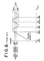
- an ON-humidity H ON and OFF-humidity H OFF having a hysteresis ⁇ H for an objective humidity H O are determined, the humidity within the controlled chamber is detected with a humidity detector, at the time points t1 and t3 when the detected humidity reaches the OFF-humidity H OFF while rising, the oscillation of the oscillator of the ultrasonic humidifier is completely stopped and, at the time points t2 and t4 when the detected humidity H reaches the ON-humidity while falling, the oscillator of the ultrasonic humidifier is oscillated with an amplitude of 100%.
- the detected humidity H at the control starting time point t o is so low that the oscillator of the ultrasonic humidifier oscillates with an amplitude of 100%.
- the hysteresis ⁇ H is provided to somewhat reduce the frequency of the ON-OFF-operations (the oscillation of 100% amplitude and the complete stop of the oscillation) of the oscillator of the ultrasonic humidifier. Precision is reduced by the provision of the hysteresis ⁇ H, but a smaller hysteresis leads to a high frequency of ON-OFF-operations which renders the oscillator prone to damage.
- the present invention has as an object to provide a humidification control system with an ultrasonic humidifer whereby the humidity within a controlled chamber can be stably and highly precisely kept at a fixed objective value without causing a cycling or offset and can be altered within a short time even if an external turbulence is applied as in case a door of the controlled chamber is opened and closed.
- the humidity within the controlled chamber is detected with a humidity detector and the proportional value, integrated value and differentiated value of the difference between the detected signal and a preset objective value signal are added to produce an operation amount signal and the oscillator of the ultrasonic humidifier is oscillated with an amplitude adjusted in response to this operation amount signal to keep the humidity within the controlled chamber substantially at said objective value.
- the sprayed amount per unit time (which shall be referred to merely as the "sprayed amount" hereinafter) from the ultrasonic humidifier varies with the ultrasonic energy generated by the oscillation of the oscillator of the ultrasonic humidifier, this ultrasonic energy is proportional to the square of the amplitude of the oscillator and therefore, by varying the amplitude of the oscillator of the ultrasonic humidifier, the sprayed amount from the ultrasonic humidifier can be continuously varied from 0 to 100%.
- the amplitude of the oscillator of the ultrasonic humidifier is adjusted in response to the operation amount signal, a sprayed amount in response to the operation amount signal will be generated from the ultrasonic humidifier.
- the humidity within the controlled chamber is detected with the humidity detector and the proportional value, integrated value and differentiated value of the difference between the detected signal and the preset objective value signal are added to form the operation amount signal, a control by a PID operation is realised in which the humidity within the controlled chamber is made a controlled amount and the sprayed amount from the ultrasonic humidifier is made an operation amount.
- the amplitude of the oscillator of the ultrasonic humidifier is adjusted in response to the operation amount signal and the oscillator of the ultrasonic humidifier is not ON and OFF (oscillated with 100% amplitude and completely stopped from oscillating) so frequently as in a conventional humidification control system and therefore is not likely to be broken.
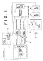
- the reference numeral 1 represents a controlled chamber and 2 represents a humidity detector for detecting the humidity within the controlled chamber 1.
- a high molecular weight humidity sensor can be used for this humidity detector 2.
- the humidity within the controlled chamber 1 is detected with the humidity detector 2 and the proportional value, integrated value and differentiated value of the difference between the detected signal and a preset objective value signal are added to produce an operation amount signal.
- the detected signal from the humidity detector 2 is put into an operation amount signal generator 3 and the operation amount signal (PID signal) is put out of the operation amount signal generator.
- the operation amount signal generator 3 is formed of an objective value setter 4, difference detector 5, integrator 6, differentiator 7, constant multipliers 8, 9 and 10 and adder 11. Therefore, when the user sets in advance an objective humidity within the controlled chamber 1 with the objective value setter 4, the difference between the detected signal from the humidity detector 2 and the preset objective value signal will be put out as a difference signal.
- This difference signal will be multiplied by a predetermined constant by the constant multiplier 8 and the proportional value of the difference will be put as a proportional signal (P signal) into the adder 11.
- the difference signal will be integrated by the integrator 6 and will be multiplied by a predetermined constant by the constant multiplier 9 and the integrated value of the difference will be put as an integrated signal (I signal) into the adder 11.
- the difference signal will be differentiated by the differentiator 7 and will be further multiplied by a predetermined constant by the constant multiplier 10 and the differentiated value of the difference will be put as a differentiated signal (D signal) into the adder 11.
- an operation amount signal (PID signal) of the sum of the proportional value, integrated value and differentiated value of the difference between the detected signal and the preset objective value signal will be put out of the adder 11.
- the humidifier 12 is an ultrasonic humidifier the oscillator 13 of which is oscillated with an amplitude adjusted in response to the operation amount signal to keep the humidity within the controlled chamber 1 constant at the preset objective value.
- the ultrasonic humidifier 12 is formed of a sprayed water tank 15 containing water 14 to be sprayed, the oscillator 13 fitted to the bottom of the sprayed water tank 15 and an oscillating circuit 16 supplying as an oscillator input signal to the oscillator 13 an alternating current voltage of the same frequency as of the ultrasonic waves.
- a rectification smoothing circuit 17 is connected on its output side to the oscillating circuit 16, an alternating current source 19 is connected to the input side of the rectification smoothing circuit 17 through a voltage regulator 18, and a direct current voltage is fed into the oscillating circuit 16.
- the alternating current source 19 is usually of the order of AC100V or AC200V and may be reduced to the required voltage through a transformer.
- oscillating circuit 16 can be used.
- an alternating current voltage of an amplitude corresponding to the size of the input direct current voltage and having the same (constant) frequency as of the ultrasonic waves is put out as an oscillator input signal.
- the voltage regulator 18 is formed of a reverse parallel circuit of thyristors 20 and 21.
- a firing angle controlling signal from a firing angle controlling signal generator 22 is put into the gates of these thyristors 20 and 21 to determine a firing angle ⁇ f which regulates the effective value of the alternating current voltage from the alternating current source 19.
- the firing angle varies from 0 to ⁇ , so the size of the direct current voltage put into the oscillating circuit varies from 100% to 0.
- noise absorbing means such as a noise limiting filter is provided between the voltage regulator 18 and rectification smoothing circuit 17.
- the operation amount signal is put into the firing angle controlling signal generator 22 so that the firing angle controlling signal may be adjusted on the basis of the operation amount signal. That is to say, the higher the level of the operation amount signal, the smaller the firing angle ⁇ f . The lower the level, the larger the firing angle ⁇ f . Therefore, in response to the operation amount signal, the size of the direct current voltage put into the oscillating circuit 16 will be adjusted and the amplitude of the oscillator input signal put out of the oscillating circuit 16 will be adjusted and thereby, in response to the operation amount signal, the amplitude of the oscillation of the oscillator 13 of the ultrasonic humidifier 12 will be adjusted.
- the sprayed amount from the ultrasonic humidifier 12 varies with the ultrasonic energy generated by the oscillation of the oscillator 13 of the ultrasonic humidifier 12 and this ultrasonic energy is proportional to the square of the amplitude of the oscillator 13, by varying the amplitude of the oscillator 13 of the ultrasonic humidifier 12, the sprayed amount from the ultrasonic humidifier 12 can be continuously varied from 0 to 100%.
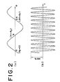
- Fig. 2 shows the case in which the sprayed amount from the ultrasonic humidifier 12 is 100%.
- Fig. 3 shows the case in which the sprayed amount is reduced.
- Fig. 4 shows the case of no spray.
- (a) is a waveform diagram of the output voltage of the voltage regulator 18 and
- (b) is a waveform diagram of the oscillator input signal put into the oscillator 13. That is to say, in the case of Fig. 2, the firing angle ⁇ f is made 0 so that the size of the direct current voltage put into the oscillating circuit 16 will be 100%, the amplitude of the oscillator input signal will be 100% and the sprayed amount will be 100%.
- the firing angle ⁇ f is made somewhat larger so that the size of the direct current voltage put into the oscillating circuit 16 will be somewhat smaller, the amplitude of the oscillator input signal will be also somewhat smaller and the spraying amount will be smaller. Further, in the case of Fig. 4, the firing angle ⁇ f is made a critical angle ⁇ fo so that the direct current voltage put into the oscillating circuit 16 will be smaller, the amplitude of the oscillator input signal will be also smaller and the sprayed amount will be 0%.
- the critical angle ⁇ fo is such an angle that spray will not be generated from the ultrasonic humidifier 12 when the firing angle ⁇ f is made larger that it but will be generated when the firing angle ⁇ f is made smaller than it.
- This critical angle ⁇ fo is based on such property that, even if the ultrasonic energy is applied to water 14 within the sprayed water tank 15 by oscillating the oscillator 13 of the ultrasonic humidifier 12, the ultrasonic energy will not be above a predetermined level. Therefore, in the case of the apparatus shown in Fig. 1, if the firing angle ⁇ f is varied from 0 to ⁇ fo , the sprayed amount from the ultrasonic humidifier 12 will be able to be continuously varied from 100% to 0.
- the sprayed amount dependent on the operation amount signal will be generated from the ultrasonic humidifier 12.
- the humidity within the controlled chamber 1 is detected with the humidity detector 2 and the proportional value, integrated value and differentiated value of the difference between the detected signal and the preset objective value signal are added to be the operation amount signal, a control by a PID operation in which the humidity within the controlled chamber 1 is made a controlled amount and the sprayed amount from the ultrasonic humidifier 12 is made an operation amount will be realised.
- the humidity within the controlled chamber can be stably and highly precisely kept at a fixed objective value without causing a cycling or offset and can be altered within a short time even if an external turbulence is applied, such as in the case the door of the controlled chamber being opened and closed.
- the amplitude of the oscillator of the ultrasonic humidifier is adjusted in response to the operation amount signal and the oscillator of the ultrasonic humidifier is not ON and OFF (oscillated with 100% amplitude and completely stopped from oscillating) so frequently as in a conventional humidification controlling system and therefore is not likely to be broken.
- the humidity will not vary substantially.
- the objective value can be varied, for example, by giving a controlling signal to the objective value setter 4 from outside.
Landscapes
- Physics & Mathematics (AREA)
- General Physics & Mathematics (AREA)
- Engineering & Computer Science (AREA)
- Automation & Control Theory (AREA)
- Air Conditioning Control Device (AREA)
- Air Humidification (AREA)
- Control Of Non-Electrical Variables (AREA)
Applications Claiming Priority (2)
| Application Number | Priority Date | Filing Date | Title |
|---|---|---|---|
| JP62040568A JPS63207945A (ja) | 1987-02-24 | 1987-02-24 | 超音波加湿器による加湿制御方式 |
| JP40568/87 | 1987-02-24 |
Publications (2)
| Publication Number | Publication Date |
|---|---|
| EP0281248A2 true EP0281248A2 (fr) | 1988-09-07 |
| EP0281248A3 EP0281248A3 (fr) | 1989-12-13 |
Family
ID=12584075
Family Applications (1)
| Application Number | Title | Priority Date | Filing Date |
|---|---|---|---|
| EP88300875A Ceased EP0281248A3 (fr) | 1987-02-24 | 1988-02-02 | Système de commande d'humidification |
Country Status (3)
| Country | Link |
|---|---|
| US (1) | US4807810A (fr) |
| EP (1) | EP0281248A3 (fr) |
| JP (1) | JPS63207945A (fr) |
Cited By (1)
| Publication number | Priority date | Publication date | Assignee | Title |
|---|---|---|---|---|
| WO2014104457A1 (fr) * | 2012-12-31 | 2014-07-03 | 주식회사 스마트로닉스 | Appareil de surveillance d'état destiné à un humidificateur par ultrasons |
Families Citing this family (4)
| Publication number | Priority date | Publication date | Assignee | Title |
|---|---|---|---|---|
| US7686285B2 (en) * | 2005-03-23 | 2010-03-30 | Barnstead Thermolyne Corporation | Environmental chamber and ultrasonic nebulizer assembly therefor |
| JP3852014B1 (ja) * | 2005-05-24 | 2006-11-29 | ダイキン工業株式会社 | 空調システム |
| CN201540004U (zh) * | 2009-11-18 | 2010-08-04 | 苏州三星电子有限公司 | 冰箱用加湿保鲜装置 |
| CN111495635A (zh) * | 2020-04-23 | 2020-08-07 | 佛山科学技术学院 | 一种自适应喷涂方法 |
Family Cites Families (8)
| Publication number | Priority date | Publication date | Assignee | Title |
|---|---|---|---|---|
| US3114091A (en) * | 1960-02-09 | 1963-12-10 | Electronic Assistance Corp | Variable power drive system |
| US3490697A (en) * | 1968-01-24 | 1970-01-20 | J J Monaghan Co Inc | Ultrasonic nebulizer |
| US3743868A (en) * | 1970-10-12 | 1973-07-03 | Denki Onkyo Co Ltd | Driving apparatus for piezoelectric ceramic elements |
| US4029064A (en) * | 1976-03-18 | 1977-06-14 | Irving J. Grace | Carburetion system for internal combustion engines |
| JPS5635696U (fr) * | 1979-08-27 | 1981-04-06 | ||
| JPS60159536A (ja) * | 1984-01-27 | 1985-08-21 | Toshiba Corp | 加湿器の自動制御装置 |
| US4535741A (en) * | 1984-02-16 | 1985-08-20 | C. Hellmuth Hertz | Fuel metering method and device |
| US4641053A (en) * | 1984-08-14 | 1987-02-03 | Matsushita Seiko Co., Ltd. | Ultrasonic liquid atomizer with an improved soft start circuit |
-
1987
- 1987-02-24 JP JP62040568A patent/JPS63207945A/ja active Pending
- 1987-06-08 US US07/059,070 patent/US4807810A/en not_active Expired - Fee Related
-
1988
- 1988-02-02 EP EP88300875A patent/EP0281248A3/fr not_active Ceased
Cited By (1)
| Publication number | Priority date | Publication date | Assignee | Title |
|---|---|---|---|---|
| WO2014104457A1 (fr) * | 2012-12-31 | 2014-07-03 | 주식회사 스마트로닉스 | Appareil de surveillance d'état destiné à un humidificateur par ultrasons |
Also Published As
| Publication number | Publication date |
|---|---|
| US4807810A (en) | 1989-02-28 |
| EP0281248A3 (fr) | 1989-12-13 |
| JPS63207945A (ja) | 1988-08-29 |
Similar Documents
| Publication | Publication Date | Title |
|---|---|---|
| US5209398A (en) | Model-based thermobalance with feedback | |
| CN1173240C (zh) | 具有自动调节的现场基地过程控制系统 | |
| US4780254A (en) | Method and apparatus for controlling the humidity in a closed chamber | |
| EP0354715A2 (fr) | Commande de débit | |
| EP0281248A2 (fr) | Système de commande d'humidification | |
| US4318062A (en) | Ultrasonic wave nebulizer driving circuit | |
| WO2001079693A2 (fr) | Dispositif de reglage de la course d'un element de pompe | |
| JPH0514107Y2 (fr) | ||
| US5506390A (en) | Thawing control apparatus and method for a microwave oven | |
| KR930000262B1 (ko) | 발전기(發電機)의 부하검출장치 | |
| JPH0324597B2 (fr) | ||
| WO1998057878A3 (fr) | Procede de regulation de la vitesse d'un ascenseur et systeme d'ascenseur | |
| JPS55105134A (en) | Supersonic humidifier of humidity regulation type | |
| KR940007181B1 (ko) | 초음파 가습기의 가습 자동조절방법 | |
| SU1043591A1 (ru) | Самонастраивающа с система автоматического регулировани | |
| SU563578A1 (ru) | Дозатор | |
| JPH07293976A (ja) | 加湿器の運転制御装置 | |
| JPS57184844A (en) | Ventilating method for parking space | |
| JPS6429903A (en) | Speed controller for motor | |
| JPS5513601A (en) | Speed controller with automatic overload regulation circuit for blower or the like | |
| JPS5593906A (en) | Controller for turbine regulating valve in pressure change operation | |
| KR0168757B1 (ko) | 초음파 방식과 히터 방식을 모두 적용한 가습기에서의 쾌속 가습방법 | |
| JPH0533111B2 (fr) | ||
| KR0151558B1 (ko) | 초음파 히터식 가습기의 가습량 조절방법 | |
| SU1199957A1 (ru) | Устройство дл регулировани турбины |
Legal Events
| Date | Code | Title | Description |
|---|---|---|---|
| PUAI | Public reference made under article 153(3) epc to a published international application that has entered the european phase |
Free format text: ORIGINAL CODE: 0009012 |
|
| AK | Designated contracting states |
Kind code of ref document: A2 Designated state(s): CH DE FR GB IT LI |
|
| PUAL | Search report despatched |
Free format text: ORIGINAL CODE: 0009013 |
|
| AK | Designated contracting states |
Kind code of ref document: A3 Designated state(s): CH DE FR GB IT LI |
|
| 17P | Request for examination filed |
Effective date: 19900606 |
|
| 17Q | First examination report despatched |
Effective date: 19921208 |
|
| STAA | Information on the status of an ep patent application or granted ep patent |
Free format text: STATUS: THE APPLICATION HAS BEEN REFUSED |
|
| 18R | Application refused |
Effective date: 19940120 |