EP0281302A1 - Procédé pour effectuer des réactions chimiques - Google Patents
Procédé pour effectuer des réactions chimiques Download PDFInfo
- Publication number
- EP0281302A1 EP0281302A1 EP88301516A EP88301516A EP0281302A1 EP 0281302 A1 EP0281302 A1 EP 0281302A1 EP 88301516 A EP88301516 A EP 88301516A EP 88301516 A EP88301516 A EP 88301516A EP 0281302 A1 EP0281302 A1 EP 0281302A1
- Authority
- EP
- European Patent Office
- Prior art keywords
- passage
- fluid
- pressure
- upflowing
- boiling
- Prior art date
- Legal status (The legal status is an assumption and is not a legal conclusion. Google has not performed a legal analysis and makes no representation as to the accuracy of the status listed.)
- Granted
Links
- 238000006243 chemical reaction Methods 0.000 title claims abstract description 171
- 238000000034 method Methods 0.000 title claims abstract description 68
- 230000008569 process Effects 0.000 title claims abstract description 51
- 239000012530 fluid Substances 0.000 claims abstract description 150
- 238000009835 boiling Methods 0.000 claims abstract description 111
- 238000009279 wet oxidation reaction Methods 0.000 claims abstract description 41
- 239000007795 chemical reaction product Substances 0.000 claims abstract description 14
- 239000007788 liquid Substances 0.000 claims description 81
- 239000000376 reactant Substances 0.000 claims description 44
- QVGXLLKOCUKJST-UHFFFAOYSA-N atomic oxygen Chemical compound [O] QVGXLLKOCUKJST-UHFFFAOYSA-N 0.000 claims description 34
- 239000001301 oxygen Substances 0.000 claims description 34
- 229910052760 oxygen Inorganic materials 0.000 claims description 34
- 230000002706 hydrostatic effect Effects 0.000 claims description 30
- 239000002699 waste material Substances 0.000 claims description 25
- 230000000977 initiatory effect Effects 0.000 claims description 19
- 238000010438 heat treatment Methods 0.000 claims description 15
- 238000012546 transfer Methods 0.000 claims description 15
- 238000011282 treatment Methods 0.000 claims description 13
- 239000010828 animal waste Substances 0.000 claims description 7
- 238000010791 quenching Methods 0.000 claims description 4
- 238000010924 continuous production Methods 0.000 claims description 2
- 239000012263 liquid product Substances 0.000 claims description 2
- 238000005086 pumping Methods 0.000 description 25
- 239000010801 sewage sludge Substances 0.000 description 11
- 239000000463 material Substances 0.000 description 10
- XLYOFNOQVPJJNP-UHFFFAOYSA-N water Substances O XLYOFNOQVPJJNP-UHFFFAOYSA-N 0.000 description 10
- 238000004140 cleaning Methods 0.000 description 7
- 230000009467 reduction Effects 0.000 description 7
- 239000010802 sludge Substances 0.000 description 7
- 230000007423 decrease Effects 0.000 description 6
- 239000007789 gas Substances 0.000 description 6
- 238000002347 injection Methods 0.000 description 6
- 239000007924 injection Substances 0.000 description 6
- 239000010865 sewage Substances 0.000 description 5
- MYMOFIZGZYHOMD-UHFFFAOYSA-N Dioxygen Chemical compound O=O MYMOFIZGZYHOMD-UHFFFAOYSA-N 0.000 description 4
- -1 for example Substances 0.000 description 4
- 239000000126 substance Substances 0.000 description 4
- 230000000694 effects Effects 0.000 description 3
- 238000009434 installation Methods 0.000 description 3
- 238000004519 manufacturing process Methods 0.000 description 3
- 238000007254 oxidation reaction Methods 0.000 description 3
- 239000002154 agricultural waste Substances 0.000 description 2
- 239000003518 caustics Substances 0.000 description 2
- 230000006835 compression Effects 0.000 description 2
- 238000007906 compression Methods 0.000 description 2
- 230000006378 damage Effects 0.000 description 2
- 230000003247 decreasing effect Effects 0.000 description 2
- 230000001627 detrimental effect Effects 0.000 description 2
- 238000002474 experimental method Methods 0.000 description 2
- 239000013529 heat transfer fluid Substances 0.000 description 2
- 239000002440 industrial waste Substances 0.000 description 2
- 239000010808 liquid waste Substances 0.000 description 2
- 239000003129 oil well Substances 0.000 description 2
- 239000007787 solid Substances 0.000 description 2
- 238000003892 spreading Methods 0.000 description 2
- 230000007480 spreading Effects 0.000 description 2
- 230000003068 static effect Effects 0.000 description 2
- 238000012935 Averaging Methods 0.000 description 1
- 208000027418 Wounds and injury Diseases 0.000 description 1
- 238000009825 accumulation Methods 0.000 description 1
- 239000002253 acid Substances 0.000 description 1
- 230000003466 anti-cipated effect Effects 0.000 description 1
- 239000003575 carbonaceous material Substances 0.000 description 1
- 239000012295 chemical reaction liquid Substances 0.000 description 1
- 238000002485 combustion reaction Methods 0.000 description 1
- 238000010276 construction Methods 0.000 description 1
- 230000001419 dependent effect Effects 0.000 description 1
- 238000006477 desulfuration reaction Methods 0.000 description 1
- 230000023556 desulfurization Effects 0.000 description 1
- 239000000446 fuel Substances 0.000 description 1
- 239000007792 gaseous phase Substances 0.000 description 1
- 208000014674 injury Diseases 0.000 description 1
- 239000007791 liquid phase Substances 0.000 description 1
- 239000000203 mixture Substances 0.000 description 1
- 239000010815 organic waste Substances 0.000 description 1
- 230000003647 oxidation Effects 0.000 description 1
- 239000011236 particulate material Substances 0.000 description 1
- 238000012545 processing Methods 0.000 description 1
- 230000003134 recirculating effect Effects 0.000 description 1
- 230000004044 response Effects 0.000 description 1
- 238000000926 separation method Methods 0.000 description 1
- 239000011343 solid material Substances 0.000 description 1
- 239000007790 solid phase Substances 0.000 description 1
- 230000002459 sustained effect Effects 0.000 description 1
- 231100000331 toxic Toxicity 0.000 description 1
- 230000002588 toxic effect Effects 0.000 description 1
- 239000002351 wastewater Substances 0.000 description 1
Images

Classifications
-
- C—CHEMISTRY; METALLURGY
- C02—TREATMENT OF WATER, WASTE WATER, SEWAGE, OR SLUDGE
- C02F—TREATMENT OF WATER, WASTE WATER, SEWAGE, OR SLUDGE
- C02F3/00—Biological treatment of water, waste water, or sewage
- C02F3/02—Aerobic processes
- C02F3/12—Activated sludge processes
- C02F3/14—Activated sludge processes using surface aeration
- C02F3/16—Activated sludge processes using surface aeration the aerator having a vertical axis
-
- C—CHEMISTRY; METALLURGY
- C02—TREATMENT OF WATER, WASTE WATER, SEWAGE, OR SLUDGE
- C02F—TREATMENT OF WATER, WASTE WATER, SEWAGE, OR SLUDGE
- C02F11/00—Treatment of sludge; Devices therefor
- C02F11/06—Treatment of sludge; Devices therefor by oxidation
- C02F11/08—Wet air oxidation
- C02F11/083—Wet air oxidation using deep well reactors
-
- B—PERFORMING OPERATIONS; TRANSPORTING
- B01—PHYSICAL OR CHEMICAL PROCESSES OR APPARATUS IN GENERAL
- B01J—CHEMICAL OR PHYSICAL PROCESSES, e.g. CATALYSIS OR COLLOID CHEMISTRY; THEIR RELEVANT APPARATUS
- B01J3/00—Processes of utilising sub-atmospheric or super-atmospheric pressure to effect chemical or physical change of matter; Apparatus therefor
- B01J3/04—Pressure vessels, e.g. autoclaves
- B01J3/042—Pressure vessels, e.g. autoclaves in the form of a tube
-
- C—CHEMISTRY; METALLURGY
- C02—TREATMENT OF WATER, WASTE WATER, SEWAGE, OR SLUDGE
- C02F—TREATMENT OF WATER, WASTE WATER, SEWAGE, OR SLUDGE
- C02F11/00—Treatment of sludge; Devices therefor
- C02F11/06—Treatment of sludge; Devices therefor by oxidation
- C02F11/08—Wet air oxidation
Definitions
- the present invention relates to improvements in methods of effecting chemical reactions and is particularly suitable for effecting accelerated chemical reactions in a crosscurrent flow, nested tube apparatus wherein the influent fluid is in heat transfer relation with the effluent.
- the process of the present invention is also particularly, although not exclusively, suitable for effecting chemical reactions in a deep well reaction apparatus, such as used for carrying out the wet oxidation of sewage sludge and other liquid waste streams.
- US- A- 4 272 383 More recently, but prior to the invention described in US- A- 4 272 383, the prior art proposed several methods for effecting wet oxidation of liquid waste streams in a deep well reaction apparatus having concentric conduits extending vertically below ground in a subterranean shaft.
- US- A- 3 449 247 for example, described a method for effecting wet oxidation of a mixture of combustible refuse and fluid sewage carried out in the lower portion of a shaft extending into the earth a sufficient distance to provide the desired pressure by the head of fluid materials in the shaft.
- the apparatus described therein included vertically-extending concentric conduits wherein the water and reactants comprising the influent stream were flowed downwardly in the outer conduit and the water and reaction product were flowed upwardly through the centre conduit in theat transfer relation with the influent. Air or oxygen-enriched air was injected in the influent liquid and the air was injected in the reaction zone at the lower extent of the conduits.
- US- A- 3 606 999 described a method and deep well reaction apparatus for treatment of fluid streams, including wet oxidation of sewage, which included a vapour trap or separation device for collecting the gaseous reactant of the reaction.
- US- A- 3 853 759 described a pyrolytic method for treating a liquid sewage stream which included limiting the combustion of the material by restricting the process to the oxygen present in the material, whereby the pressure at the bottom of the influent column supposedly caused the heated material to rise in the effluent column.
- US- A- 4 564 458 which is of later date than US- A- 4 272 383, described a method of effecting wet oxidation of organic waste materials in a waste water stream in a deep well reaction apparatus at super-critical temperatures and pressures, wherein the wet oxidation reaction was initiated by flowing an electric current through the water at the bottom of the well to generate resistance heat. It should be considered, however, that these prior art descriptions, excluding US- A- 4 272 383, are purely theoretical and generally impractical and particularly that the deep well reaction apparatus described therein were not built or tested.
- US- A- 4 272 383 states that no pumping pressure will be required to sustain a continuous flow through the deep well reaction apparatus and that there is no pressure differential across the wall dividing the concentric tubes or pipes.
- a substantial pumping pressure is required during start-up and continued operation of a deep well reaction apparatus. More importantly, the required pumping pressure increases during operation because of plugging of the downcomer and the build-up and accummulation of organic and inorganic scale or fouling.
- any boiling of the liquid in the conduits could result in "geysering" if the boiling continued for any substantial period of time.
- the conduits extended into the earth to more than 1524 metres (5000 feet).
- the combined lengths of the upcomer and downcomer conduits totals about 3220 meters (about two miles). If geysering occurred as a result of boiling, the resultant geyser of steam, reaction products and sewage, for example, could cause injury and substantial damage to the deep well reaction apparatus.
- boiling of the effluent fluid results in unexpected improvements in the efficiency of the operation of a deep well reaction apparatus, including reduced pumping pressures, increased mass flow rates, reduced downtime for cleaning and decreased start-up time. It is therefore a further object of the present invention to initiate boiling of the effluent liquid in the upcomer conduit to reduce the pumping pressure and improve the efficiency of the reaction apparatus.
- the process for effecting chemical reactions of this invention is particularly, although not exclusively, adapted for subterranean apparatuses including deep well reaction systems.
- the method of the present invention may be utilized for treating or reacting various liquids, including effecting wet oxidation reactions of various industrial and municipal wastes entrained in a liquid, such as, for example, water.
- the process of the present invention is particularly suitable for effecting wet oxidation reactions of various animal wastes, including municipal sewage sludge, organic agricultural wastes, and industrial wastes.
- the chemical reactions resulting from the process or method of the present invention may also include various treatments of solid materials entrained in a fluid, including the treatment of non-waste materials, such as the desulfurization of carbonaceous materials.
- the process or method of the present invention is also suitable for effecting the chemical reaction wherein one of the reactants is gaseous, such as oxygen, oxygen-enriched air or air.
- a process for effecting chemical reactions between at least two reactants which comprises:
- the boiling of the fluid in the upflowing passage is controlled to periodically boil the fluid in the upflowing passage at predetermined timed intervals.
- the reactants include a gaseous reactant and the downflowing passage includes a reaction zone in the lower portion thereof having a predetermined elevated reaction temperature, the gaseous reactant being introduced into the downflowing passage adjacent the upper extent of the reaction zone.
- the influent fluid may be heated in the downflowing passage to initiate the chemical reaction and thereafter the temperature of the influent fluid in the downflowing passage is controlled by adding or removing heat to maintain a fluid coulmn in the downflowing passage and prevent boiling of the influent fluid in the downflowing passage.
- the temperature of the fluid in the upflowing passage may be sensed at a predetermined depth and the outlet pressure of the fluid is controlled to maintain boiling of the fluid in the upflowing passage at the predetermined depth.
- the boiling of the fluid in the upflowing passage may be controlled and limited to the upper portion of the upflowing passage.
- the present invention also provides a process for effecting chemical reactions between at least two reactants, which comprises:
- the pipes have different diameters with the smaller pipe nested within the larger pipe and the larger pipe having a closed end, the reaction zone having an elevated temperature bing established near the closed end and the fluid in the second pipe boiling adjacent the end of the pipe spaced from the reaction zone.
- the present invention further provides a process for effecting a chemical reaction between at least two reactants, which comprises:
- the present invention still further provides a process for effecting a chemical reaction between at least two reactants, which comprises:
- the present invention provides a continuous process for effecting exothermic reactions between at least two reactions, which comprises:
- a predetermined pressure is maintained in the upflowing passage sufficient to prevent boiling of the upwardly flowing fluid during initiation of the exothermic reaction, thereafter reducing the upflowing fluid passage pressure to cause boiling of the flud in the upflowing passage.
- the upflowing fluid passage pressure may be periodically adjusted to periodically boil the fluid in the upcoming passage at predetermined timed intervals.
- the temperature of the fluid in the upflowing passage may be sensed at a predetermined depth, then reducing the pressure in the upflowing passage to the boiling pressure of the fluid at the predetermined depth temperature.
- one of the reactants may be a gaseous reactant which is introduced into the downflowing passage adjacent the upper extent of the reaction zone.
- the present invention is particularly applicable to the wet oxidation treatment of waste material.
- the present invention provides a process for wet oxidation treatment of a waste material having a predetermined COD suspended in a fluid, which comprises:
- the temperature of the effluent fluid in the upflowing passages may be sensed at a predetermined depth, then reducing the pressure in the upflowing passage to the boiling pressure of the effluent fluid at the predetermined depth temperature.
- the upflowing fluid passage pressure may be periodically adjusted to periodically boil the fluid in the upcoming passage at predetermined timed intervals.
- the present invention also provides a process for effecting wet oxidation reactions of waste suspended in a liquid in a reaction apparatus which includes generally vertical upcomer and downcomer pipes extending below ground in a subterranean opening, the pipes having different diameters with the smaller pipe nested within the larger pipe providing crosscurrent flow, which comprises:
- a predetermined pressure may be established on the effluent in the upcomer pipe during initiation of the wet oxidation reaction, then reducing the effluent pressure to initiate boiling of the upflowing effluent liquid in the upcomer pipe.
- the present invention further provides a process for effecting wet oxidation reactions of organic animal waste suspended in a liquid in a reaction apparatus which includes generally vertical pipes extending below ground in a subterranean hole including upcomer and downcomer pipes in fluid heat transfer relation, which comprises:
- the temperature of the effluent liquid in the upcomer pipe may be sensed at a predetrmined depth and periodically and intermittently reducing the pressure in the upcomer pipe to initiate boiling at the temperature sensed.
- the mass flow rate through the pipes is increased sufficiently to periodically quench the boiling in the upcomer pipe while maintaining the wet oxidation reaction.
- oxygen is injected in the influent fluid adjacent the upper extent of the reaction zone of the downflowing passage or downcomer pipe.
- the process for effecting chemical reactions of the present invention includes flowing an influent fluid, including at least one of the reactants downwardly through a downflowing conduit or downcomer which extends below ground in a subterranean opening or shaft, such as a conventional oil well shaft.
- the column of fluid in the downcomer thereby defines a predetermined pressure and heat is added to initiate and maintain the desired chemical reaction, forming reaction products. Where the reaction is exothermic, the heat of reaction may be sufficient to sustain the reaction.
- the method of the present invention then includes flowing the fluid and reaction products comprising the effluent upwardly through an upflowing conduit or upcomer to ground level.
- the method of the present invention further includes boiling the fluid in the upcomer conduit to reduce the hydrostatic pressure in the upcomer conduit and increase the mass flow rate through the system.
- the reaction may be initiated by adding heat to the influent fluid, preferably near the lower extent of the reaction apparatus, creating a reaction zone in the lower portion of the conduit.
- one of the reactants is a gas, such as, for example, oxygen
- the gas in the process of the present invention is preferably introduced in the downcomer adjacent the upper extent of the reaction zone, to limit the reduction of the density of the fluid column in the downcomer, further reducing the required pumping pressure.
- the pumping pressure on the influent fluid may be eliminated, wherein the hydrostatic pressure of the fluid column in the downcomer is sufficient to flow the influent downwardly, and the boiling fluid in the upcomer is sufficient to raise the fluid in the upcomer conduit.
- the process of the present invention substantially reduces the required pumping pressure.
- Boiling of the effluent fluid may be initiated by either reducing the back pressure in the effluent upcomer or by increasing the temperature of the effluent fluid.
- boiling of the effluent fluid is initiated by reducing the back pressure in the upcomer conduit.
- the chemical reaction is initiated in the downcomer conduit by heating the fluid and reactants in the reaction zone while maintaining a predetermined back pressure in the upcomer conduit.
- a temperature sensing means is provided in the upcomer conduit at a predetermined depth, and the back pressure in the upcomer conduit is then reduced to initiate and maintain boiling of the effluent fluid at the predetermined depth temperature.
- the temperature can be sensed in the downcomer. It is thus possible to control the boiling of the effluent to a predetermined depth or to periodically boil the effluent fluid a predetermined time intervals.
- the boiling of the effluent in the upcomer conduit results in several important advantages.
- the boiling of the effluent fluid substantially reduces the required pumping pressure, resulting not only in energy savings, but also limiting the requirement for shutdown and cleaning of the system.
- the boiling of the effluent fluid permits a substantial increase in the mass flow rate through the system, increasing the efficiency of the system and further reducing the cost of processing.
- the boiling of the fluid in the upcomer reduces the required reaction temperatures resulting in further energy saving. It has also been found that the boiling of the effluent fluid spreads the reaction zone, increasing the efficiency of the system.
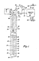
- treatment apparatus 20 is a vertical down-hole or deep well fluid reaction apparatus suitable for treatment of various combustible materials in a fluid or aqueous stream, wherein one of the reactants is gas, such as, for example, oxygen, oxygen-enriched air, or air.
- the influent stream may comprise organic animal waste, such as, for example, diluted municipal sewage sludge, suspended or entrained in a water stream, and oxygen is injected into the effluent at ground level or at various levels in the downcomer conduit.
- the preferred fluid treatment apparatus comprises a plurality of nested pipes or conduits which extend generally vertically in a subterranean shaft or opening.
- the conduits may extend approximately 1600 metres (approximately one mile) into the ground to define annuli which, when filled with a fluid waste stream, create a hydrostatic column of very substantial fluid pressure. It will be understood, however, that the length of the conduits will vary depending on the type of material being treated and the desired reaction or treatment. It may also be suitable to utilize the reaction apparatus which may be used in the method of the present invention for a variety of reactions of this type in which solid particulate material, for example, is suspended or dissolved in a circulating fluid.
- each vertically-extending conduit or pipe typically comprises a plurality of sections which are interconncted in serial alignment in a string, similar to the pipes in an oil well.
- the length of each pipe is about 12 metres (about 40 feet) long, and the total length is about 1585 metres (about 5,200 feet).
- the flow rate through the reactor of the fluid being treated typically ranges from about 303 to 1514 litres (about 80 to 400 gallons) per minute in a substantially continuous operation.
- the preferred reaction in a deep well reaction apparatus of the type disclosed herein is an exothermic reaction, such as, for example, the wet oxidation of municipal sewage sludge described, wherein the heat of reaction maintains the reaction in the continuous fluid stream.
- the wet oxidation reaction is initiated at about 177°C (about 350°F).
- the reaction initiation temperature of 177°C (350°F) is reached at about 610 metres (about 2000 feet) below ground surface.
- conduit 24 surrounds conduit 24 to define an upcomer passage or annulus 25.
- conduit 24 surrounds a heat exchanger 26 to define a downcomer passage or annulus 27.
- heat exchanger 26 may be utilized to control the temperature of the reaction vessel, whereby heat may be added or removed.
- the illustrated embodiment of the heat exchanger 26 includes a downcomer pipe 28, which is surrounded by a upcomer pipe 30, defining an upcomer annulus 31. Oil, water, steam or other heat exchange medium is circulated through the heat exchanger 26 to heat or cool the reaction vessel, as required.
- one object of the heat exchanger is to initiate the desired reaction in the lower portion of the reactor, which is referred to herein as the reaction zone. Heated oil, water or steam is therefore transferred downwardly through the downcomer pipe 28 to the lower portion of the reactor, where the hottest heat exchange medium is in, heat transfer relation with the downwardly flowing influent in annulus 27. Another object of the heat exchanger is to remove heat when the reaction becomes autogenic, as necessary. Another function of the heat exchanger is to stabilize the temperature and thereby the operation of the system. It is possible, however, to initiate the deisred reaction by other means, including a single steam pipe which extends into the reaction vessel, particularly where an aqueous system is utilized. Electrical heaters may also be considered. However, the most preferred system includes a heat exchanger for addition or removal of heat, as described.
- the municipal sewage sludge which contains combustible orgnaic material is introduced into downcomer annulus 27 as an influent waste stream which flows downwardly through annulus 27 which is in contact with heat exchanger 26.
- the oxidation reaction typically begins at about 610 metres (about 2000 feet) below ground surface at a fluid waste stream temperature of about 177°C (about 350°F).
- the reaction proceeds slowly as the fluid waste stream continues to flow downwardly and the temperature of the fluid waste stream increases to about 260°C (about 500°F) at a depth of approximately 914 to 1524 metres (approximately 3000 to 5000 feet) below ground level.
- the exothermic wet oxidation reaction is then quite vigorous, establishing a reaction zone, particularly in the downcomer annulus 27, and considerably heat is generated.
- the bottom 32 of conduit 24 is open such that the reaction products and liquid flow from the downcomer annulus 27 to the upcomer annulus 25.
- the heated fluid, which contains the reaction products is then flowed upwardly through upcomer annulus 25 as the effluent waste stream.
- the heat of the upcoming effluent is transferred to the downcoming influent through pipe 24.
- downcomer pipe 28 of heat exchanger 26 is provided with an open end 36, and the upcomer pipe 30 has a closed end 38.
- the heat transfer fluid such as oil, is received through downcomer pipe 28 and flows back up through annulus 31, thereby recirculating the heat transfer fluid and transferring the heat primarily to the influent stream in the lower portion of annulus 27 to establish the reaction zone, as described.
- Figure 1 also illustrates schematically the preferred method of injecting oxygen or an oxygen-rich gas in the process for effecting chemical reactions of the present invention.
- the pressure of the hydrostatic column of the influent in annulus 27 will be dependent upon the density of the fluid.
- the gaseous reactant is preferably injected below ground level 40 at or near the upper extent of the reaction zone, which is the initiation temperature of the desired reaction.
- the initiation temperature is about 177°C (about 350°F) and typically occurs at about 610 metres (about 2000 feet) below ground level 40.
- One desirable effect of boiling the effluent in the upcomer annulus 25 is a spreading of the reaction zone.
- the reaction zone may begin at about 305 metres (1000 feet), and the oxygen should then be injected at about 305 metres (about 1000 feet). It may therefore be desirable to have multiple oxygen injection locations, particularly where the liquid in the upcomer annulus 25 is periodically boiled at timed intervals, as described hereinbelow. Further, as described in our copending European Patent Application 88 300668.6, it may be desired to periodically pulse oxygen into the influent annulus 27 at or near ground level to reduce fouling in the downcomer annulus.
- the system includes a source of oxygen 42 which may be a compressed air tank or other source of oxygen.
- a source of oxygen may be liquid oxygen which is pumped to a liquid oxygen atmospheric vapourizer, not shown, to provide substantially pure oxygen under pressure.
- the oxygen is delivered to the reaction apparatus through lines 44 and 46 and is controlled by valves 48 and 50, respectively.
- the first line 44 extends to a predetermined depth below ground surface level 40 to inject air through opening 52 adjacent the upper extent of the reaction zone when the liquid in the upcomer annulus 25 is not boiling, and line 46 extends to a lesser depth for injection of oxygen through opening 54 when boiling in the upcomer annulus 25 is initiated.
- the lower injection point 52 may be approximately 610 metres (approximately 2000 feet) below ground surface level 40
- injection point 54 may be approximately 305 metres (approximately 1000 feet) below ground surface.
- Influent fluid is introduced into the reactor through line 56 and flows downwardly through the downcomer annulus or passage 27.
- heat is transferred from heat exchanger 26 to the downflowing influent to initiate the wet oxidation reaction.
- the temperature of the influent liquid reaches approximately 177°C (approximately 350°F)
- the wet oxidation reaction is initiated.
- water is initially used as the influent until the temperature of the influent water reaches approximately 177°C (approximately 350°F), and the water is then replaced with diluted sewage sludge having a predetermined chemical oxygen demand (COD).
- COOD chemical oxygen demand
- the mass of oxygen required to complete the oxidation reaction is termed the chemical oxidation demand of the sewage sludge.
- oxygen is also introduced, preferably through the lower injection point 52.
- the influent is then received through the open end 32 of conduit 24 and circulated upwardly through the upcomer annulus 25, which is in heat transfer relation with the fluid in the downcomer annulus 27.
- the effluent is received from the upcomer annulus 25 in line 58 and transferred to a conventional separator vessel 60 where the effluent is separated into a gaseous phase at the top of the separator vessel and a liquid/solid phase at the lower portion of the separator vessel.
- the gas and vapours are removed from the separator vessel through line 62, which is controlled by valve 64, and the liquid and solids are removed from the bottom of the vessel through line 66 and controlled by valve 68.
- the "back pressure" of the system which is the pressure on the influent in the outer upflowing annulus 25, is controlled by valve 70.
- the valve 70 is opened a predetermined amount to maintain a predetermined back pressure on the effluent stream.
- the back pressure on the effluent is maintained to prevent boiling.
- the pressure is reduced to the boiling pressure of the effluent liquid at a predetermined temperature, the effluent will boil. As described above, it was believed by those skilled in the art that sustained boiling in the effluent stream would result in "geysering" of the system.
- the boiling would travel down the upcomer annulus 25 until it reached the opening 32 to the influent annulus 27, resulting in a blow-out of steam, untreated sewage, and reaction products. Every effort was therefore made to avoid boiling in the upcomer passage 25 by controlling the back pressure through valve 70. The back pressure was always maintained to prevent boiling, or the pressure was immediately increased when boiling was initiated spontaneously.
- the deep well reaction apparatus shown in Figure 1 is specifically adapted to initiate and maintain boiling of the effluent in the upcomer passage or annulus 25 or, alternatively, periodically boil the effluent.
- the apparatus includes a conventional temperature indicator control (TIC) 72 having a temperature sensing line 74 which extends downwardly into the upflowing effluent passage or annulus 25.
- the sensor line 74 extends into the effluent passage 25 to a point adjacent the upper extent of the reaction zone when boiling is initiated in the upcomer passage 25.
- the temperature indicator control 72 is connected by line 76 to a conventional pressure indicator control (PIC) 78.
- PIC pressure indicator control
- the pressure indicator control 78 includes a pressure sensor line 80 connected to the effluent output conduit 58 and a control line 82 connected to valve 70.
- the liquid in the upcomer passage 25 may be periodically boiled when the back pressure of the effluent in line 58 reaches a predetermined maximum pressure.
- the pressure in effluent conduit 58 is sensed by the pressure indicator control 78 through line 80, and the back pressure, which is controlled by valve 70, is then reduced by control line 82 to the boiling pressure at a predetermined depth temperature as indicated by the temperature sensor line 74 of temperature indicator control 72.
- the boiling in the upcomer can be maintained by operation of the pressure indicator control, as described. That is, the back pressure is continuously adjusted by adjusting valve 70 to maintain boiling.
- boiling in the upcomer passage 25 can be periodically initiated at predetermined timed intervals to improve the efficiency of the system, as shown below.
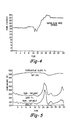
- Figures 2 to 5 illustrate the effect of boiling the effluent liqid in the upcomer upon the pressure profile of the reaction vessel (Figure 2), the sludge mass flow rate (Figure 3), the process vapour pressure or oxygen feed rate to the reaction vessel ( Figure 4) and the reactor temperatures ( Figure 5).
- the graphs of Figures 2 to 5 are taken from computer readouts of the experimental operation of the deep well reaction apparatus as illustrated in Figure 1.
- the pumping pressure influent was averaging about 3792 kPa (about 550 psig), and the pumping pressure exceeded 4137 kPa (600 psig), at about 10 a.m.(10); actual pressure readings before the boiling experiments were 4247 kPa (616 psig).
- the effluent pressure was maintained at about 896 kPa (about 130 psig) to avoid the boiling of the effluent, and Delta P (Influent Pressure less Effluent Pressure), which is the pressure drop across the reaction vessel, averaged about 2896 kPa (about 420 psig).
- boiling was initiated in the iffluent beginning at about noon (12.00 hours) by manually reducing the back pressure (effluent pressure) about 50 psi (see Figure 2).
- the reduction in the influent back pressure was accomplished by opening control valve 70 in Figure 1.
- the manual reduction in the back pressure (effluent pressure) initiated boiling of the effluent liquid, which resulted in a disproportionate decrease in the influent pressure or pumping pressure to less than 2413 kpa (350 psig).
- the pressure drop (Delta P) across the reaction vessel is determined by the frictional pressure drop and the difference in the static heads between the downcomer and the upcomer. In addition to these pressure drops, fouling caused by scale build-up on the conduit walls, and plugging within the downcomer caused by restriction of the downcomer area, were responsible for a greater than calculated pressure drop.
- the pressure drop across the reactor requires pumping of the influent liquid and compression of the influent oxygen to overcome the pressure drop.
- the plugging of the downcomer and, to a lesser extent, the scaling of the reaction conduit walls results in an increasing inlet pressure with operating time. Shutdowns are normally required to remove the plug with a backwash or a sectional caustic wash, or to remove both the plug and the scale with a sequential caustic and acid washes.
- a control loop may be established, as shown in Figure 1, wherein the back pressure is continuously adjusted by adjusting the opening through valve 70 based upon the temperature at a predetermined depth as sensed by the temperature sensor line 74 of the temperature-indicating control 72.
- the temperature is maintained by increasing or decreasing the back pressure as indicated by Figure 5. That is, a decrease in the back pressure will cause an increase in the temperature of the effluent, maintaining boiling in the upcomer. Further, boiling can be maintained to a predetermined depth with safe operation while avoiding geysering. Alternatively, the boiling of the effluent in the upcomer may be quenched eventually by substantially increasing the mass flow rate.
- the mass flow rate through the reaction vessel was doubled by manually reducing the back pressure and initiating boiling of the effluent in the upcomer.
- the resultant advantages of boiling the effluent in the upcomer are several.
- the reduction in the pressure drop across the reaction vessel results in a lower inlet or pumping pressure and consequent savings in electric power required for pumping of the liquid influent and compression of the gas influent.
- Capital savings result because the pressure rating of the equipment can be reduced.
- boiling of the effluent results in an increased residence time in an existing reaction vessel due to more efficient utilization of the heat exchange portion.
- boiling of the effluent fluid resulted in a spreading or increase of the reaction zone.
- residence time further results in lowered toxic material discharges in industrial designs, for example.
- boiling of the influent fluid reduces the number of shutdowns required for cleaning and greater production rates for a longer period of time. This results in significant reductions of operating and capital costs due to the increased on-line factors.
- the increased production rate between wash cycles reduces the fuel required during start-up and chemical consumption during washes. Due to the fewer wash cycles required, the lifetime of the reaction vessel further inceases.
Landscapes
- Chemical & Material Sciences (AREA)
- Organic Chemistry (AREA)
- Life Sciences & Earth Sciences (AREA)
- Environmental & Geological Engineering (AREA)
- Water Supply & Treatment (AREA)
- Engineering & Computer Science (AREA)
- Hydrology & Water Resources (AREA)
- Chemical Kinetics & Catalysis (AREA)
- Biodiversity & Conservation Biology (AREA)
- Microbiology (AREA)
- Treatment Of Water By Oxidation Or Reduction (AREA)
- Physical Or Chemical Processes And Apparatus (AREA)
- Treatment Of Sludge (AREA)
- Crystals, And After-Treatments Of Crystals (AREA)
- Organic Low-Molecular-Weight Compounds And Preparation Thereof (AREA)
Priority Applications (1)
| Application Number | Priority Date | Filing Date | Title |
|---|---|---|---|
| AT88301516T ATE76329T1 (de) | 1987-02-24 | 1988-02-23 | Durchfuehrungsverfahren von chemischen reaktionen. |
Applications Claiming Priority (2)
| Application Number | Priority Date | Filing Date | Title |
|---|---|---|---|
| US17659 | 1987-02-24 | ||
| US07/017,659 US4744908A (en) | 1987-02-24 | 1987-02-24 | Process for effecting chemical reactions |
Publications (2)
| Publication Number | Publication Date |
|---|---|
| EP0281302A1 true EP0281302A1 (fr) | 1988-09-07 |
| EP0281302B1 EP0281302B1 (fr) | 1992-05-20 |
Family
ID=21783841
Family Applications (1)
| Application Number | Title | Priority Date | Filing Date |
|---|---|---|---|
| EP88301516A Expired - Lifetime EP0281302B1 (fr) | 1987-02-24 | 1988-02-23 | Procédé pour effectuer des réactions chimiques |
Country Status (9)
| Country | Link |
|---|---|
| US (1) | US4744908A (fr) |
| EP (1) | EP0281302B1 (fr) |
| JP (1) | JPH0796098B2 (fr) |
| KR (1) | KR920002069B1 (fr) |
| AT (1) | ATE76329T1 (fr) |
| CA (1) | CA1307596C (fr) |
| DE (1) | DE3871183D1 (fr) |
| DK (1) | DK93888A (fr) |
| IE (1) | IE60732B1 (fr) |
Cited By (2)
| Publication number | Priority date | Publication date | Assignee | Title |
|---|---|---|---|---|
| EP0389698A1 (fr) * | 1987-09-14 | 1990-10-03 | WASTE TREATMENT PATENTS & RESEARCH N.V. | Procédé et dispositif pour la production et liquéfaction des gaz |
| DE19732080A1 (de) * | 1997-07-25 | 1999-04-22 | Atz Evus | Verfahren zur kontinuierlichen Behandlung organischer Substanzen |
Families Citing this family (26)
| Publication number | Priority date | Publication date | Assignee | Title |
|---|---|---|---|---|
| US5422002A (en) * | 1986-09-30 | 1995-06-06 | East Anglian Water Company | Treatment of water to remove gas vacuolate cyanobacteria |
| US4818371A (en) * | 1987-06-05 | 1989-04-04 | Resource Technology Associates | Viscosity reduction by direct oxidative heating |
| US4874560A (en) * | 1988-06-06 | 1989-10-17 | Oxidyne Corporation | Apparatus for effecting selected patterns of fluid flow |
| US5160581A (en) * | 1990-06-01 | 1992-11-03 | Titmas And Associates Incorporated | Method for oxygen bleaching paper pulp |
| US5620606A (en) | 1994-08-01 | 1997-04-15 | Rpc Waste Management Services, Inc. | Method and apparatus for reacting oxidizable matter with particles |
| US5755974A (en) | 1994-08-01 | 1998-05-26 | Rpc Waste Management Services, Inc. | Method and apparatus for reacting oxidizable matter with a salt |
| US5551472A (en) | 1994-08-01 | 1996-09-03 | Rpc Waste Management Services, Inc. | Pressure reduction system and method |
| JP2905864B2 (ja) * | 1995-01-18 | 1999-06-14 | 工業技術院長 | 有機性汚泥の油化処理方法 |
| US5536385A (en) * | 1995-03-03 | 1996-07-16 | Envirocorp Services & Technology, Inc. | Production and purification of contaminated effluent streams containing ammonium sulfate and ammonia |
| US6017460A (en) | 1996-06-07 | 2000-01-25 | Chematur Engineering Ab | Heating and reaction system and method using recycle reactor |
| US5814292A (en) * | 1996-12-19 | 1998-09-29 | Energy Research Group | Comprehensive energy producing methods for aqueous phase oxidation |
| SE518803C2 (sv) | 1999-09-03 | 2002-11-26 | Chematur Eng Ab | Metod och reaktionssystem med högt tryck och hög temperatur som är lämpat för superkritisk vattenoxidation |
| US20060060541A1 (en) * | 2004-09-23 | 2006-03-23 | Abazajian Armen N | Waste disposal method and apparatus using wet oxidation and deep well injection |
| SE528840C2 (sv) * | 2004-11-15 | 2007-02-27 | Chematur Eng Ab | Reaktor och förfarande för överkritisk vattenoxidation |
| SE529006C2 (sv) * | 2004-11-15 | 2007-04-03 | Chematur Eng Ab | Förfarande och system för överkritisk vattenoxidation av en ström som innehåller oxiderbart material |
| BRMU8701289U2 (pt) * | 2007-07-11 | 2009-02-25 | Ivane Rodrigues De Souza | aparelho para produzir biocarvço |
| US7951988B2 (en) * | 2009-04-01 | 2011-05-31 | Earth Renewal Group, Llc | Aqueous phase oxidation process |
| US9272936B2 (en) | 2009-04-01 | 2016-03-01 | Earth Renewal Group, Llc | Waste treatment process |
| US8168847B2 (en) * | 2009-04-01 | 2012-05-01 | Earth Renewal Group, Llc | Aqueous phase oxidation process |
| US7915474B2 (en) * | 2009-04-01 | 2011-03-29 | Earth Renewal Group, Llc | Aqueous phase oxidation process |
| US8481800B2 (en) * | 2009-04-01 | 2013-07-09 | Earth Renewal Group, Llc | Aqueous phase oxidation process |
| US8115047B2 (en) * | 2009-04-01 | 2012-02-14 | Earth Renewal Group, Llc | Aqueous phase oxidation process |
| KR101044701B1 (ko) | 2009-09-30 | 2011-06-28 | 한국건설기술연구원 | 열변형 완충이 가능한 중력식 습식산화 반응기 |
| AU2016430162B2 (en) * | 2016-11-15 | 2020-10-01 | Metso Metals Oy | Process and plant for the treatment of carbonaceous slurry |
| US11077328B2 (en) | 2019-10-14 | 2021-08-03 | David Stanley Moulton | Apparatus for improving vertical flow reactor utility |
| US11821287B2 (en) * | 2020-01-21 | 2023-11-21 | Solenis Technologies, L.P. | Geothermal well stimulation and silca based deposit removal |
Citations (3)
| Publication number | Priority date | Publication date | Assignee | Title |
|---|---|---|---|---|
| US4272383A (en) * | 1978-03-17 | 1981-06-09 | Mcgrew Jay Lininger | Method and apparatus for effecting subsurface, controlled, accelerated chemical reactions |
| US4564458A (en) * | 1983-11-10 | 1986-01-14 | Burleson James C | Method and apparatus for disposal of a broad spectrum of waste featuring oxidation of waste |
| US4671351A (en) * | 1985-07-17 | 1987-06-09 | Vertech Treatment Systems, Inc. | Fluid treatment apparatus and heat exchanger |
Family Cites Families (1)
| Publication number | Priority date | Publication date | Assignee | Title |
|---|---|---|---|---|
| JPH0316886Y2 (fr) * | 1986-08-05 | 1991-04-10 |
-
1987
- 1987-02-24 US US07/017,659 patent/US4744908A/en not_active Expired - Lifetime
- 1987-08-14 KR KR1019870008956A patent/KR920002069B1/ko not_active Expired
-
1988
- 1988-01-14 CA CA000556514A patent/CA1307596C/fr not_active Expired - Fee Related
- 1988-02-03 JP JP63023656A patent/JPH0796098B2/ja not_active Expired - Fee Related
- 1988-02-23 AT AT88301516T patent/ATE76329T1/de not_active IP Right Cessation
- 1988-02-23 EP EP88301516A patent/EP0281302B1/fr not_active Expired - Lifetime
- 1988-02-23 DK DK093888A patent/DK93888A/da not_active Application Discontinuation
- 1988-02-23 DE DE8888301516T patent/DE3871183D1/de not_active Expired - Fee Related
- 1988-02-24 IE IE50688A patent/IE60732B1/en not_active IP Right Cessation
Patent Citations (3)
| Publication number | Priority date | Publication date | Assignee | Title |
|---|---|---|---|---|
| US4272383A (en) * | 1978-03-17 | 1981-06-09 | Mcgrew Jay Lininger | Method and apparatus for effecting subsurface, controlled, accelerated chemical reactions |
| US4564458A (en) * | 1983-11-10 | 1986-01-14 | Burleson James C | Method and apparatus for disposal of a broad spectrum of waste featuring oxidation of waste |
| US4671351A (en) * | 1985-07-17 | 1987-06-09 | Vertech Treatment Systems, Inc. | Fluid treatment apparatus and heat exchanger |
Cited By (3)
| Publication number | Priority date | Publication date | Assignee | Title |
|---|---|---|---|---|
| EP0389698A1 (fr) * | 1987-09-14 | 1990-10-03 | WASTE TREATMENT PATENTS & RESEARCH N.V. | Procédé et dispositif pour la production et liquéfaction des gaz |
| DE19732080A1 (de) * | 1997-07-25 | 1999-04-22 | Atz Evus | Verfahren zur kontinuierlichen Behandlung organischer Substanzen |
| DE19732080B4 (de) * | 1997-07-25 | 2004-11-04 | Applikations- Und Technikzentrum Für Energieverfahrens-, Umwelt- Und Strömungstechnik (Atz-Evus) | Verfahren und Vorrichtung zum kontinuierlichen Abbau organischer Substanzen |
Also Published As
| Publication number | Publication date |
|---|---|
| JPH0796098B2 (ja) | 1995-10-18 |
| DE3871183D1 (de) | 1992-06-25 |
| US4744908A (en) | 1988-05-17 |
| IE880506L (en) | 1988-08-24 |
| CA1307596C (fr) | 1992-09-15 |
| EP0281302B1 (fr) | 1992-05-20 |
| DK93888A (da) | 1988-08-25 |
| DK93888D0 (da) | 1988-02-23 |
| KR920002069B1 (ko) | 1992-03-10 |
| ATE76329T1 (de) | 1992-06-15 |
| JPS63232842A (ja) | 1988-09-28 |
| IE60732B1 (en) | 1994-08-10 |
| KR880009872A (ko) | 1988-10-05 |
Similar Documents
| Publication | Publication Date | Title |
|---|---|---|
| EP0281302B1 (fr) | Procédé pour effectuer des réactions chimiques | |
| EP0282276B1 (fr) | Appareil et méthode pour effectuer des réactions chimiques | |
| US4774006A (en) | Fluid treatment method | |
| CA1299844C (fr) | Dispositif et methode pour mener des reactions chimiques dans des conditionssupercritiques | |
| US4594164A (en) | Method and apparatus for conducting chemical reactions at supercritical conditions | |
| US4272383A (en) | Method and apparatus for effecting subsurface, controlled, accelerated chemical reactions | |
| US3606999A (en) | Method of and apparatus for carrying out a chemical or physical process | |
| JPS63100927A (ja) | 制御された化学反応を行わせる方法及び反応装置 | |
| US4849025A (en) | Decoking hydrocarbon reactors by wet oxidation | |
| EP0029701B1 (fr) | Procédé et appareil pour empêcher le dépôt de solides dans un réacteur tubulaire | |
| US20190185361A1 (en) | Supercritical water oxidation reactor and process | |
| KR910008720B1 (ko) | 화학반응제어를 위한 반응방법 및 장치 | |
| SU1088648A3 (ru) | Способ проведени подземных химических реакций и установка дл его осуществлени | |
| RU2085706C1 (ru) | Способ очистки скважины от парафиносмолистых отложений и устройство для его осущестления | |
| CA1327952C (fr) | Appareil de traitement thermique d'un flux d'hydrocarbures | |
| RU185703U1 (ru) | Реактор проточного типа для осуществления реакции сверхкритического водного окисления | |
| WO2004083128A1 (fr) | Appareil et procede pour effectuer l'oxydation humide de fond de puits | |
| SU1740576A1 (ru) | Устройство дл реагентной обработки водозаборной скважины | |
| CN119735258A (zh) | 一种采用带压温控密闭反应的水质改性工艺 | |
| IE60659B1 (en) | Method and reaction apparatus for effecting controlled chemical reactions | |
| HK1135641A (en) | Thermally autogenous subsurface chemical reactor & method |
Legal Events
| Date | Code | Title | Description |
|---|---|---|---|
| PUAI | Public reference made under article 153(3) epc to a published international application that has entered the european phase |
Free format text: ORIGINAL CODE: 0009012 |
|
| AK | Designated contracting states |
Kind code of ref document: A1 Designated state(s): AT BE CH DE GB IT LI NL SE |
|
| 17P | Request for examination filed |
Effective date: 19890228 |
|
| 17Q | First examination report despatched |
Effective date: 19900213 |
|
| RAP1 | Party data changed (applicant data changed or rights of an application transferred) |
Owner name: WASTE TREATMENT PATENTS & RESEARCH N.V. |
|
| GRAA | (expected) grant |
Free format text: ORIGINAL CODE: 0009210 |
|
| AK | Designated contracting states |
Kind code of ref document: B1 Designated state(s): AT BE CH DE GB IT LI NL SE |
|
| REF | Corresponds to: |
Ref document number: 76329 Country of ref document: AT Date of ref document: 19920615 Kind code of ref document: T |
|
| ITF | It: translation for a ep patent filed | ||
| REF | Corresponds to: |
Ref document number: 3871183 Country of ref document: DE Date of ref document: 19920625 |
|
| PLBE | No opposition filed within time limit |
Free format text: ORIGINAL CODE: 0009261 |
|
| STAA | Information on the status of an ep patent application or granted ep patent |
Free format text: STATUS: NO OPPOSITION FILED WITHIN TIME LIMIT |
|
| 26N | No opposition filed | ||
| EAL | Se: european patent in force in sweden |
Ref document number: 88301516.6 |
|
| REG | Reference to a national code |
Ref country code: GB Ref legal event code: IF02 |
|
| PGFP | Annual fee paid to national office [announced via postgrant information from national office to epo] |
Ref country code: NL Payment date: 20051229 Year of fee payment: 19 |
|
| PGFP | Annual fee paid to national office [announced via postgrant information from national office to epo] |
Ref country code: SE Payment date: 20060207 Year of fee payment: 19 |
|
| PGFP | Annual fee paid to national office [announced via postgrant information from national office to epo] |
Ref country code: AT Payment date: 20060213 Year of fee payment: 19 |
|
| PGFP | Annual fee paid to national office [announced via postgrant information from national office to epo] |
Ref country code: DE Payment date: 20060216 Year of fee payment: 19 |
|
| PGFP | Annual fee paid to national office [announced via postgrant information from national office to epo] |
Ref country code: GB Payment date: 20060222 Year of fee payment: 19 |
|
| PGFP | Annual fee paid to national office [announced via postgrant information from national office to epo] |
Ref country code: IT Payment date: 20060228 Year of fee payment: 19 |
|
| PGFP | Annual fee paid to national office [announced via postgrant information from national office to epo] |
Ref country code: CH Payment date: 20060301 Year of fee payment: 19 |
|
| PGFP | Annual fee paid to national office [announced via postgrant information from national office to epo] |
Ref country code: BE Payment date: 20060410 Year of fee payment: 19 |
|
| PG25 | Lapsed in a contracting state [announced via postgrant information from national office to epo] |
Ref country code: SE Free format text: LAPSE BECAUSE OF NON-PAYMENT OF DUE FEES Effective date: 20070224 |
|
| PG25 | Lapsed in a contracting state [announced via postgrant information from national office to epo] |
Ref country code: LI Free format text: LAPSE BECAUSE OF NON-PAYMENT OF DUE FEES Effective date: 20070228 Ref country code: CH Free format text: LAPSE BECAUSE OF NON-PAYMENT OF DUE FEES Effective date: 20070228 |
|
| REG | Reference to a national code |
Ref country code: CH Ref legal event code: PL |
|
| EUG | Se: european patent has lapsed | ||
| GBPC | Gb: european patent ceased through non-payment of renewal fee |
Effective date: 20070223 |
|
| NLV4 | Nl: lapsed or anulled due to non-payment of the annual fee |
Effective date: 20070901 |
|
| PG25 | Lapsed in a contracting state [announced via postgrant information from national office to epo] |
Ref country code: AT Free format text: LAPSE BECAUSE OF NON-PAYMENT OF DUE FEES Effective date: 20070223 |
|
| BERE | Be: lapsed |
Owner name: *WASTE TREATMENT PATENTS & RESEARCH N.V. Effective date: 20070228 |
|
| PG25 | Lapsed in a contracting state [announced via postgrant information from national office to epo] |
Ref country code: BE Free format text: LAPSE BECAUSE OF NON-PAYMENT OF DUE FEES Effective date: 20070228 |
|
| PG25 | Lapsed in a contracting state [announced via postgrant information from national office to epo] |
Ref country code: NL Free format text: LAPSE BECAUSE OF NON-PAYMENT OF DUE FEES Effective date: 20070901 Ref country code: DE Free format text: LAPSE BECAUSE OF NON-PAYMENT OF DUE FEES Effective date: 20070901 |
|
| PG25 | Lapsed in a contracting state [announced via postgrant information from national office to epo] |
Ref country code: GB Free format text: LAPSE BECAUSE OF NON-PAYMENT OF DUE FEES Effective date: 20070223 |
|
| PG25 | Lapsed in a contracting state [announced via postgrant information from national office to epo] |
Ref country code: IT Free format text: LAPSE BECAUSE OF NON-PAYMENT OF DUE FEES Effective date: 20070223 |