EP0281337B1 - Dispositif détecteur du rapport de mélange d'essence et d'alcool ou semblable - Google Patents
Dispositif détecteur du rapport de mélange d'essence et d'alcool ou semblable Download PDFInfo
- Publication number
- EP0281337B1 EP0281337B1 EP19880301710 EP88301710A EP0281337B1 EP 0281337 B1 EP0281337 B1 EP 0281337B1 EP 19880301710 EP19880301710 EP 19880301710 EP 88301710 A EP88301710 A EP 88301710A EP 0281337 B1 EP0281337 B1 EP 0281337B1
- Authority
- EP
- European Patent Office
- Prior art keywords
- column
- circumferential surface
- light
- critical angle
- emitting diode
- Prior art date
- Legal status (The legal status is an assumption and is not a legal conclusion. Google has not performed a legal analysis and makes no representation as to the accuracy of the status listed.)
- Expired - Lifetime
Links
- LFQSCWFLJHTTHZ-UHFFFAOYSA-N Ethanol Chemical compound CCO LFQSCWFLJHTTHZ-UHFFFAOYSA-N 0.000 title claims description 13
- 239000007788 liquid Substances 0.000 claims description 36
- 239000000203 mixture Substances 0.000 claims description 24
- 238000000034 method Methods 0.000 claims description 5
- 239000005308 flint glass Substances 0.000 claims description 4
- 238000004519 manufacturing process Methods 0.000 claims description 3
- 239000011248 coating agent Substances 0.000 claims description 2
- 238000000576 coating method Methods 0.000 claims description 2
- 239000000446 fuel Substances 0.000 description 15
- 239000011521 glass Substances 0.000 description 8
- 238000002485 combustion reaction Methods 0.000 description 6
- 239000012466 permeate Substances 0.000 description 4
- 230000007423 decrease Effects 0.000 description 3
- 230000003247 decreasing effect Effects 0.000 description 3
- NJPPVKZQTLUDBO-UHFFFAOYSA-N novaluron Chemical compound C1=C(Cl)C(OC(F)(F)C(OC(F)(F)F)F)=CC=C1NC(=O)NC(=O)C1=C(F)C=CC=C1F NJPPVKZQTLUDBO-UHFFFAOYSA-N 0.000 description 3
- XLYOFNOQVPJJNP-UHFFFAOYSA-N water Substances O XLYOFNOQVPJJNP-UHFFFAOYSA-N 0.000 description 3
- 239000003822 epoxy resin Substances 0.000 description 2
- 238000002347 injection Methods 0.000 description 2
- 239000007924 injection Substances 0.000 description 2
- 239000004033 plastic Substances 0.000 description 2
- 229920003023 plastic Polymers 0.000 description 2
- 229920000647 polyepoxide Polymers 0.000 description 2
- 230000002940 repellent Effects 0.000 description 2
- 239000005871 repellent Substances 0.000 description 2
- FAPWRFPIFSIZLT-UHFFFAOYSA-M Sodium chloride Chemical compound [Na+].[Cl-] FAPWRFPIFSIZLT-UHFFFAOYSA-M 0.000 description 1
- 238000010521 absorption reaction Methods 0.000 description 1
- 239000000853 adhesive Substances 0.000 description 1
- 230000001070 adhesive effect Effects 0.000 description 1
- 230000002411 adverse Effects 0.000 description 1
- PBAYDYUZOSNJGU-UHFFFAOYSA-N chelidonic acid Natural products OC(=O)C1=CC(=O)C=C(C(O)=O)O1 PBAYDYUZOSNJGU-UHFFFAOYSA-N 0.000 description 1
- 238000005260 corrosion Methods 0.000 description 1
- 230000007797 corrosion Effects 0.000 description 1
- 238000010586 diagram Methods 0.000 description 1
- 239000011888 foil Substances 0.000 description 1
- 238000005065 mining Methods 0.000 description 1
- 230000003287 optical effect Effects 0.000 description 1
- 230000002093 peripheral effect Effects 0.000 description 1
- 229920001296 polysiloxane Polymers 0.000 description 1
- 229920005989 resin Polymers 0.000 description 1
- 239000011347 resin Substances 0.000 description 1
- 239000011780 sodium chloride Substances 0.000 description 1
- 229920003002 synthetic resin Polymers 0.000 description 1
- 239000000057 synthetic resin Substances 0.000 description 1
- 230000009897 systematic effect Effects 0.000 description 1
- 238000003466 welding Methods 0.000 description 1
Images


Classifications
-
- G—PHYSICS
- G01—MEASURING; TESTING
- G01N—INVESTIGATING OR ANALYSING MATERIALS BY DETERMINING THEIR CHEMICAL OR PHYSICAL PROPERTIES
- G01N21/00—Investigating or analysing materials by the use of optical means, i.e. using sub-millimetre waves, infrared, visible or ultraviolet light
- G01N21/17—Systems in which incident light is modified in accordance with the properties of the material investigated
- G01N21/41—Refractivity; Phase-affecting properties, e.g. optical path length
- G01N21/43—Refractivity; Phase-affecting properties, e.g. optical path length by measuring critical angle
-
- G—PHYSICS
- G01—MEASURING; TESTING
- G01J—MEASUREMENT OF INTENSITY, VELOCITY, SPECTRAL CONTENT, POLARISATION, PHASE OR PULSE CHARACTERISTICS OF INFRARED, VISIBLE OR ULTRAVIOLET LIGHT; COLORIMETRY; RADIATION PYROMETRY
- G01J1/00—Photometry, e.g. photographic exposure meter
- G01J1/10—Photometry, e.g. photographic exposure meter by comparison with reference light or electric value provisionally void
- G01J1/16—Photometry, e.g. photographic exposure meter by comparison with reference light or electric value provisionally void using electric radiation detectors
- G01J1/1626—Arrangements with two photodetectors, the signals of which are compared
- G01J2001/1636—Arrangements with two photodetectors, the signals of which are compared one detector directly monitoring the source, e.g. also impulse time controlling
-
- G—PHYSICS
- G01—MEASURING; TESTING
- G01J—MEASUREMENT OF INTENSITY, VELOCITY, SPECTRAL CONTENT, POLARISATION, PHASE OR PULSE CHARACTERISTICS OF INFRARED, VISIBLE OR ULTRAVIOLET LIGHT; COLORIMETRY; RADIATION PYROMETRY
- G01J1/00—Photometry, e.g. photographic exposure meter
- G01J1/42—Photometry, e.g. photographic exposure meter using electric radiation detectors
- G01J1/44—Electric circuits
- G01J2001/444—Compensating; Calibrating, e.g. dark current, temperature drift, noise reduction or baseline correction; Adjusting
-
- G—PHYSICS
- G01—MEASURING; TESTING
- G01N—INVESTIGATING OR ANALYSING MATERIALS BY DETERMINING THEIR CHEMICAL OR PHYSICAL PROPERTIES
- G01N21/00—Investigating or analysing materials by the use of optical means, i.e. using sub-millimetre waves, infrared, visible or ultraviolet light
- G01N21/84—Systems specially adapted for particular applications
- G01N21/85—Investigating moving fluids or granular solids
-
- G—PHYSICS
- G01—MEASURING; TESTING
- G01N—INVESTIGATING OR ANALYSING MATERIALS BY DETERMINING THEIR CHEMICAL OR PHYSICAL PROPERTIES
- G01N2201/00—Features of devices classified in G01N21/00
- G01N2201/06—Illumination; Optics
- G01N2201/062—LED's
- G01N2201/0621—Supply
Definitions
- This invention relates to a detector device in which a mixing ratio such as, for example, gasoline and alcohol is optically measured, and adjusted for use in fuel of an internal combustion engine.
- FR-2487610 shows a detector device with an optically permeable column, one end of which is made reflective. Light emitting and receiving elements are positioned adjacent the opposite end of the column from the reflection end.
- the preamble of claim 1 is based on this disclosure.
- a detector device in contact with a mixture of gasoline and alcohol or the like for detecting a predetermined range of mixture ratios thereof comprising: an optically permeable column, one end of which is coated with a light-reflective layer, a circumferential surface of said column being at least partially immersed in the mixture; a light emitting diode and a photo diode each disposed adjacent the end of the column remote from said light-reflective layer and aligned along a diameter of said column; light beams from said light emitting diode forming a light path such that said light beams pass through said column to be incident on and reflected from one of said circumferential surface and said light-reflective layer, so as to be incident on the other of said light reflective layer and said circumferential surface and reflected therefrom onto said photo diode, the light beams incident on said circumferential surface of said column at less than a critical angle being refracted to said liquid while the light beams incident on said circumferential surface at
- a method of making a device for detecting a predetermined range of mixture ratios of gasoline and alcohol or the like comprising the steps of: coating one end of an optically permeable column with a light reflective layer; mounting a light-emitting diode and a photodiode adjacent the end of the column remote from the reflective layer, so that in use light beams from the light emitting diode pass through the column to be incident on and reflected from one of the circumferential surface of the column and the light reflective layer, are incident on the other of the light reflective layer and the circumferential surface and reflected therefrom onto the photodiode, the light beams incident on the circumferential surface of said column at less than a critical angle being refracted to the liquid and the light beams incident on the circumferential surface at more than the critical angle being totally internally reflected, the critical angle depending on the mixture ratio of the liquid; characterised by the steps of determining the diameter and length of the column so that said light beams are reflected onto the
- numeral 1 designates a detector device according to this invention which is placed into an intermediate pipe 23a between a fuel reservoir 20 and a pressure regulator 23 as elucidated hereafter in Fig.5.
- the pipe 23 has a aperture (Ap) at its circumferential wall to communicate the innerside space and outside atmosphere.
- R0 O-ring
- the column 3 has a specular layer (La) coated at its one end positioned opposite to the casing 2 to serve as light reflecting means.
- a pedestal 4 placed, on which a light emitting diode 5 and a photo diode 6 are arranged in coplanar relationship.
- a temperature compensation light emitting diode (PDc) is placed on the pedestal 4 by means of a support 107 to position remote from the light emiting diode 5.
- the light emitting diode 5 and the photo diodes 6. (PDc) are moulded in integral with a transparent epoxy resin or silicone (M) to fill a space between the glass 3 and the pedestal 4, except for a remaining pneumatic layer.
- light beams from the light emitting diode 5 permeates into the column 3 through its one end to be incident on a boundary (Bo) between the outer surface of the column 3 and the mixing liquid (Lq), the light beams incident on the boundary (Bo) at less than a critical angle being totally refracted, while the light beams incident on the boundary (Bo) at more than a critical angle being totally reflected, the critical angle depending on a mixing degree of the mixing liquid (Lq).
- the photo diode 6 is adapted to receive the light beams reflected at the boundary (Bo), or at the specular layer(La) to go back through the column 3 to fall thereon so as to generate an output in accordance with the light intensity received.
- a principle incorporated into this invention is shown in Figs.3 and 4.
- the light beams from the diode 5 permeates into the column 3 through one end to reflect at the boundary (Bo) only once with an angle of more than a critical angle ( ⁇ M), and reach at the specular layer (La) so as to reflect back through the column 3 to the photo diode 6, when a mining ratio of the liquid (Lq) is such as, for example, 0:10 (alcohol only).
- the light beams from the diode 5 permeates into the column 3 through one end to reflect at the boundary (Bo) only once with an angl of more than a critical angle ( ⁇ G), and reach at the spcular layer (La) so as to reflect back through the column 3 o the photo diode 6, when a mixing ratio of the liquid (Lq is such as, for example, 100:0 (gasoline only).
- denotations R1 and R2 are distances each measured from the diode 5 to the outer peripheral of the column 3 along the diametrical direction.
- Denotations L and x are a lengthwise dimension of the column 3 and a thickness dimension of the pipe 3a, with denotation d as a distance between lower end of the column 3 and the light emitting diode 6.
- R1tan ⁇ M ⁇ d+x L ⁇ R1tan ⁇ G-d are obtained. These two representations provides R1 and L with cocrete values.
- relationship (2L+1-x)/tan ⁇ G ⁇ R2 ⁇ (L+d)/tan ⁇ M is obtained as elucidated hereafter, allowing to provide R2 with a concrete value.
- Figs. 5 and 6 show exmples in which the light emitting diode 5 is placed at a cener of the column 3, the radius of which is depicted by R. in Fig.5, the light beams permeated into the column 3, firstly reflected at the boundary (Bo), and reached at the specular layer (La).
- Representations Rtan ⁇ M ⁇ (x+d ) and (L+d) ⁇ Rtan ⁇ G are obtained. From the two representations, R ⁇ (x+d)/tan ⁇ M ⁇ L ⁇ Rtan ⁇ G-d are obtained, providing R, L with concrete values.
- FIG. 7 shows a control system in which a detector device according to this invention is associated with an internal combustion engine for a motor vehicle.
- numeral 37 designates an engine cylinder
- numeral 50 being an ignition key
- numeral 51 being a control circuit
- numeral 55 a battery cell serving as a power source
- numeral 20 a fuel reservior.
- Numeral 21 designates a fuel pump
- numeral 23 being a pressure regulator which is introduced from the fuel reservior 20 by way of the intermediate pipe 23a which the detector device 1 is mounted.
- Numeral 24 shows an injector, numeral 26 being a cold start injector, numeral 25 being an ignition coil, numeral 30 an air cleaner, numeral 31 an air valve, numeral 32 an air flow meter, numeral 33 a throttle valve, numeral 34 a position sensor for the throttle valve 33, numeral 35 an inake pipe, numeral 36 an exhaust pipe, numeral 52 a sensor for detecting air-fuel ratio of the fuel, numeral 53 a temperature sensor for a water cooler circulating in a jacket of the engine cylinder 37.
- an actuation of the igition key 50 allows to activate the engine, and at the same time, supplying a power source to the control ciruit 51.
- the mixing liquid fuel of gasoline and alcohol n the reservior 20 is supplied to the injector 24 through afuel pipe 22 by means of fuel pump 21.
- the inector 24 works to supply the fuel to the intake pipe 35 atthe most appropriately quantity of injection calculaed to the operating condition of the engine.
- control circuit51 impresses a voltage across the light emitting diode 6 to emanate light beams which passes through the synthetic resin layer (M) and the glass 3 to reach at the boundary (Bo) between outer surface of the glass 3 and the mixing liquid fuel (Lq).
- variation of mixing ratio of the fuel liquid changes its refraction index to cause change of the critical angle when the light beams permeate through the glass 3 to reflect at the boundary (Bo).
- the change of the critical angle influences on the quantity of the light beams falling on the photo diode 6 to change the output produced therefrom.
- the relationship between the mixing ratio of the liquid (Lq) and the quantity of the light beams fell on the photo diode 6, are previously obtained as data from the change of the refraction index of the mixing liquid to be stored by the control circuit 51.
- the output from the photo diode 6 allows the control circuit 51 to calculate the most appropriate quantity of injection fuel so as to maintain a good output of the engine.
- the light emitting diode 5 and the photo diode 6 is located at the position of identical side, so that thickness dimension of the detector device 1 is reduced.
- the dimension of the column 3 is such to mininize the amount of the light beams absorbed within the column 3, and preventing unnecessary light beams from falling on the photo diode 6 since the light emitting diode positions to avoid reflection light beams, thus ensuring to measure a mixing ratio with high accuracy.
- the casing 2 required to encase the diodes 5,6 is a unitary one to reduce the number of assembly processes so as to facilitate assembly, conducive to an improved production.
- the temperature compensation (PDc) is in the shape of a rectangular chip, and located opposite to the light emitting diode 5 to be in the neighborhood of the photo diode 6 as mentioned herebefore.
- the location of the diode (PDc) is such that the diode (PDc) receives the light beams only incident on the boundary at more than a critical angle so as to always maintain a constant quantity of the light beams received, regardless of the mixing ratio of the liquid (Lq).
- the temperature compensation photo diode (PDc) is incorporated into an electronic circuit shown n Fig. 8.
- the diode (PDc) is connected across positive and negative terminals 70a, 70b of first operational amplifier 70.
- a common point of the negative terminal 70b and the diode (PDc) is connected to an output terminal 70c of the amplifier 70 by way of an electrical resistance r1.
- the output terminal 70c is connected to a negative terminal 71b of second amplifier 71 through an electrical resistance r2.
- the amplifier 71 has a positive terminal 71a grounded through a suitable resistance (rm).
- Across the negative terminal 71b and the output terminal 71c is a condenser 72 connected to prevent an adverse hunting action.
- a common point of the condenser 72 and the output terminal 71c is grounded by way of the light emitting diode 5. Further, a common point of the output terminal 71c and the light emitting diode 5 is connected to a negative terminal 73b of third operational amplifier 73 through an electrical resistance r3, the amplifier 73 connecting a negative terminal 73b to an output terminal 73c through an electrical resistance r4.
- a predetermined input voltage (V) proportionately divided by resistances r7 and r8 is supplied through a resistance r5.
- the ratio of resistances r3 and r4 is predetermined to be equivalent to that of the resistances r5 and r6.
- a common point of the resistance r4 and the positive terminal 73c is connected to a negative terminal 74b of fourth operational amplifier 74.
- the amplifier 74 serves as an calculator which, by way of its positive terminal 74a, receives an output from an operational amplifier 12 to which the photo diode 6 is connected, and at the same time, receiving an output from the third amplifier 73 by way of the negative terminal 74b.
- the terminal 74 produces an output, the value of which is equivalent to the output difference between the amplifiers 12 and 73.
- the amplifier 71 works to control a quantity of current supplied to the light emitting diode 5 so as to hold the diode (PDc) at a predetermined output level, and leading to a uniform output of the photo diode 6 unless the liquid (Lq) of gasoline and alcohol changes its refraction index.
- the refraction of the liquid changes in accordance with the ambient temperature so that the relationship between temperature (T) and output (V) of the photo diode 6 is as seen at solid line in Fig.9.
- the relationship between the ambient temperature (T) and voltage drop (V across the terminals of the light emitting diode 5, is as seen in Fig. 10, so that the voltage drop (V) decreases with the increase of the ambient temperature (T).
- the voltage impressed acros the teriminals of the light emitting diode 5 is forwarded to the third operational amplifier 73 through the positive terminal 73a, so that the amplifier 73 allows the output terminal 73c to produce voltage (V) which progressively steps up with the increase of the ambient temperature as depicted in Fig.11.
- the voltage (V) thus changing is applied to the light emitting diode 5 through the output terminal 71c of the amplifier 71 to act the diode 5 to decrease its light emitting degree. This leads to decreasing the output of the photo diode 6 so that the output of the photo diode 6 is maintained substantially at a certain level irrespective of the ambient temperature as seen by broken lines in Fig.9.
- the light emitting diode 5 deteriorates with a long period of use, in such a degree that the light intensity reduces by a few percent with a thousand operating hours, and reducing by ten or twenty percent wit ten thousand operating hours.
- the decreased output of the first amplifier 70 is applied to the negative terminal 71b of the second operational amplifier 71 to be amplified.
- the amplified output is forwarded through the output terminal 71c to apply it across the light emitting diode 5 to compensate for the loss of the light emitting quantity.
- a light repellent means may be either a metallic foil layer, or a plastic layer having a mirrored surface, otherwise a light repellent means may be provided with the end of the column by means of spattering.
- flint glass 3 instead of the flint glass 3, a reinforced glass or a corrosion resistant plastics may be employed.
- a mixing liquid fuel is not confined only to gasoline and alcohol.
- the detector device according to this invention may be incorporated into a monitor device in which concentration of sugared water and saline water is being continuously detected. This may has a significance particularly in the circle of food industry.
- the light beams from the diode 5 may reflect only once at the boundary (Bo) with an incident angle as more than a critical angle when a mixing ratio of alcohol is between 30 percent and 60 percent at the time of determining a diametrical and lengthwise dimensions of the column 3.
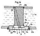
- Fig.14 shows other embodiment of this invention in which the column 3 extends at its length to fully traverse the diameter of the pipe 23a with the background as the same in that of Figs. 12 and 13.
- the pipe 23a in registration with the aperture (Ap), the pipe 23a is provided with a hole 104 into which the column 3 extends its upper end, and liquid-tightly sealed by means of an O-ring 105.
- the specular layer (La) is applied by means of such as, for example, an adhesive.
Landscapes
- Physics & Mathematics (AREA)
- Health & Medical Sciences (AREA)
- Life Sciences & Earth Sciences (AREA)
- Chemical & Material Sciences (AREA)
- Analytical Chemistry (AREA)
- Biochemistry (AREA)
- General Health & Medical Sciences (AREA)
- General Physics & Mathematics (AREA)
- Immunology (AREA)
- Pathology (AREA)
- Investigating Or Analysing Materials By Optical Means (AREA)
Claims (10)
- Dispositif de détection au contact d'un mélange d'essence et d'alcool ou autre pour détecter une gamme prédéterminée de rapports de mélange de ceux-ci, comprenant :
une colonne optiquement perméable, dont une extrémité est enduite d'une couche photoréfléchissante, une surface périphérique de ladite colonne étant au moins partiellement plongée dans le mélange;
une diode électroluminescente et une photodiode disposées chacune au voisinage immédiat de l'extrémité de la colonne éloignée de ladite couche photoréfléchissante et alignées sur un diamètre de ladite colonne;
des rayons lumineux issus de ladite diode électroluminescente formant un parcours lumineux tel que lesdits rayons lumineux passent par ladite colonne pour frapper et être réfléchis par l'une de ladite surface périphérique et de ladite couche photoréfléchissante de façon à frapper l'autre de ladite couche photoréfléchissante et de ladite couche périphérique et à être réfléchis depuis celle-ci sur ladite photodiode, les rayons lumineux qui frappent ladite surface périphérique de ladite colonne selon un angle inférieur à un angle critique étant réfractés dans ledit liquide tandis que les rayons lumineux qui frappent ladite surface périphérique selon un angle supérieur à l'angle critique sont réfléchis d'une manière totalement interne, l'angle critique dépendant du rapport de mélange du liquide; caractérisé en ce que le diamètre et la longueur de la colonne sont déterminés de façon que lesdits rayons lumineux soient réfléchis sur la photodiode selon une gamme d'angles prédéterminée entre un premier angle correspondant à l'angle critique lorsque ledit rapport de mélange du liquide est à la limite inférieure de la gamme prédéterminée de rapports de mélange à détecter et un second angle correspondant à l'angle critique lorsque ledit rapport de mélange du liquide est à la limite supérieure de la gamme prédéterminée. - Dispositif selon la revendication 1, dans lequel ladite diode électroluminescente est disposée pour être alignée avec l'axe central de ladite colonne.
- Dispositif selon la revendication 1 ou 2, dans lequel ladite colonne optiquement perméable est en flint-glass.
- Dispositif selon l'une quelconque des revendications précédentes, dans lequel certains rayons lumineux sont réfléchis d'abord depuis la surface périphérique, et d'autres sont réfléchis d'abord depuis l'extrémité réfléchissante de la colonne.
- Dispositif selon l'une quelconque des revendications précédentes, dans lequel la colonne a une section transversale sensiblement rectangulaire dans un plan parallèle à l'axe de la colonne, et la photodiode et la diode électroluminescente sont alignées sensiblement parallèlement à l'extrémité réfléchissante de la colonne.
- Dispositif selon la revendication 5, dans lequel les dimensions de la colonne sont conçues selon les formules:


où R₁ est la plus petite distance entre la diode électroluminescente et la surface périphérique de la colonne,
R₂ est la plus grande distance entre la diode électroluminescente et la surface périphérique de la colonne
d est la distance entre les diodes et la colonne,
x est la distance entre l'extrémité de la colonne au voisinage immédiat de la diode et la limite à laquelle est plongée la surface périphérique de la colonne,
ϑm est l'angle d'incidence critique à l'extrémité inférieure de la gamme d'angles prédéterminée, et
ϑg est l'angle d'incidence critique à l'extrémité supérieure de la gamme d'angles prédéterminée. - Procédé pour réaliser un dispositif de détection d'une gamme prédéterminée de rapports de mélange d'essence et d'alcool ou autre, comprenant les étapes consistant à:
appliquer une couche photoréfléchissante sur une extrémité d'une colonne optiquement perméable;
monter une diode électroluminescente et une photodiode au voisinage immédiat de l'extrémité de la colonne éloignée de la couche photoréfléchissante, de façon que, en service, des rayons lumineux issus de la diode électroluminescente passent par la colonne pour frapper et être réfléchis par l'une de la surface périphérique de la colonne et de la couche photoréfléchissante, frappent l'autre de la couche photoréfléchissante et de la surface périphérique et soient réfléchis depuis celle-ci sur la photodiode, les rayons lumineux qui frappent la surface périphérique de ladite colonne selon un angle inférieur à un angle critique étant réfractés dans le liquide et les rayons lumineux qui frappent la surface périphérique selon un angle supérieur à l'angle critique étant réfléchis d'une manière totalement interne, l'angle critique dépendant du rapport de mélange du liquide; caractérisé par les étapes consistant à déterminer le diamètre et la longueur de la colonne de façon que lesdits rayons lumineux soient réfléchis sur la photodiode selon une gamme d'angles prédéterminée entre un premier angle correspondant à l'angle critique lorsque le rapport de mélange du liquide est à la limite inférieure d'une gamme prédéterminée correspondante de rapports de mélange à détecter et un second angle correspondant à l'angle cri-tique lorsque le rapport de mélange du liquide est à la limite supérieure de la gamme prédéterminée. - Procédé selon la revendication 7, dans lequel certains rayons lumineux sont réfléchis d'abord depuis la surface périphérique, et d'autres sont réfléchis d'abord par l'extrémité réfléchissante de la colonne.
- Procédé selon la revendication 7 ou 8, dans lequel la colonne a une section transversale rectangulaire dans un plan parallèle à l'axe de la colonne, et la photodiode et la diode électroluminescente sont alignées sensiblement parallèlement à l'extrémité réfléchissante de la colonne.
- Procédé selon la revendication 9, dans lequel les dimensions de la colonne sont conçues selon les formules:


où R₁ est la plus petite distance entre la diode électroluminescente et la surface périphérique de la colonne,
R₂ est la plus grande distance entre la diode électroluminescente et la surface périphérique de la colonne,
d est la distance entre les diodes et la colonne,
x est la distance entre l'extrémité de la colonne au voisinage immédiat de la diode et la limite à laquelle est plongée la surface périphérique de la colonne,
ϑm est l'angle d'incidence critique à l'extrémité inférieure de la gamme d'angles prédéterminée, et
ϑg est l'angle d'incidence critique à l'extrémité supérieure de la gamme d'angles prédéterminée.
Applications Claiming Priority (4)
| Application Number | Priority Date | Filing Date | Title |
|---|---|---|---|
| JP62043960A JPS63210645A (ja) | 1987-02-26 | 1987-02-26 | ガソリン−アルコ−ルなどの流体混合比検出装置 |
| JP43960/87 | 1987-02-26 | ||
| JP33289/88 | 1988-02-16 | ||
| JP3328988A JPH01207647A (ja) | 1988-02-16 | 1988-02-16 | ガソリンとアルコールなどの流体混合比検出装置 |
Publications (3)
| Publication Number | Publication Date |
|---|---|
| EP0281337A2 EP0281337A2 (fr) | 1988-09-07 |
| EP0281337A3 EP0281337A3 (en) | 1989-12-13 |
| EP0281337B1 true EP0281337B1 (fr) | 1993-07-21 |
Family
ID=26371966
Family Applications (1)
| Application Number | Title | Priority Date | Filing Date |
|---|---|---|---|
| EP19880301710 Expired - Lifetime EP0281337B1 (fr) | 1987-02-26 | 1988-02-26 | Dispositif détecteur du rapport de mélange d'essence et d'alcool ou semblable |
Country Status (2)
| Country | Link |
|---|---|
| EP (1) | EP0281337B1 (fr) |
| DE (1) | DE3882396T2 (fr) |
Families Citing this family (5)
| Publication number | Priority date | Publication date | Assignee | Title |
|---|---|---|---|---|
| US4962746A (en) * | 1988-11-23 | 1990-10-16 | Ngk Spark Plug Co., Ltd. | Mixing liquid ratio detector device |
| JPH03186733A (ja) * | 1989-12-15 | 1991-08-14 | Ngk Spark Plug Co Ltd | 被測定液体の混合割合検出器 |
| EP0546827B1 (fr) * | 1991-12-10 | 1997-04-09 | Ngk Spark Plug Co., Ltd | Dispositif de commande et de détection des conditions de combustion par un moteur à combustion interne |
| FI108259B (fi) * | 1998-01-30 | 2001-12-14 | Janesko Oy | Refraktometri |
| FI20135064A7 (fi) | 2013-01-23 | 2014-07-24 | Janesko Oy | Menetelmä taitekertoimen mittaamiseksi ja refraktometri |
Family Cites Families (4)
| Publication number | Priority date | Publication date | Assignee | Title |
|---|---|---|---|---|
| US3299770A (en) * | 1961-09-22 | 1967-01-24 | Honeywell Inc | Light to electrical energy transforming apparatus for continuously indicating the index of refraction |
| JPS5351768A (en) * | 1976-10-20 | 1978-05-11 | Yuasa Battery Co Ltd | Apparatus for measuring specific gravity of battery electrolyte |
| NL191373C (nl) * | 1980-07-15 | 1995-06-16 | Tno | Inrichting voor het sturen van de brandstoftoevoer aan een verbrandingsmotor. |
| GB2089032A (en) * | 1980-11-18 | 1982-06-16 | Us Energy | Device for Detecting Specific Gravity of Liquid |
-
1988
- 1988-02-26 EP EP19880301710 patent/EP0281337B1/fr not_active Expired - Lifetime
- 1988-02-26 DE DE19883882396 patent/DE3882396T2/de not_active Expired - Fee Related
Also Published As
| Publication number | Publication date |
|---|---|
| EP0281337A3 (en) | 1989-12-13 |
| EP0281337A2 (fr) | 1988-09-07 |
| DE3882396T2 (de) | 1993-11-18 |
| DE3882396D1 (de) | 1993-08-26 |
Similar Documents
| Publication | Publication Date | Title |
|---|---|---|
| US4770129A (en) | Sensor for mixing ratio of gasoline and alcohol | |
| JP4906583B2 (ja) | 燃料性状検出装置 | |
| KR910004217B1 (ko) | 알콜함유율 검출장치 | |
| US20100241362A1 (en) | Fuel property determining apparatus | |
| US4895444A (en) | Detector device for mixing ratio for gasoline and alcohol or the like | |
| JP4948117B2 (ja) | 燃料性状検出装置 | |
| EP0370807B1 (fr) | Dispositif détecteur du rapport d'un mélange de liquides | |
| EP0281337A2 (fr) | Dispositif détecteur du rapport de mélange d'essence et d'alcool ou semblable | |
| US4912319A (en) | Detector device for mixing ratio for gasoline and alcohol or the like | |
| EP0483725A2 (fr) | Détecteur de teneur d'alcool | |
| JPS6291840A (ja) | 燃料性状検出器 | |
| JPS62180244A (ja) | アルコ−ル混合燃料の混合比センサ | |
| JPH01196542A (ja) | ガリソン・アルコールなどの流体混合比検出装置 | |
| JPH01207647A (ja) | ガソリンとアルコールなどの流体混合比検出装置 | |
| EP0433080B1 (fr) | Dispositif pour mesurer le rapport de mélange de plusieurs liquides | |
| JPH0549178B2 (fr) | ||
| JPH01170839A (ja) | ガソリン・アルコールなどの流体混合比検出装置 | |
| JPS63215945A (ja) | ガソリン−アルコ−ルなどの流体混合比検出装置 | |
| JPS62180245A (ja) | アルコ−ル混合燃料の混合比センサ | |
| JPS62127646A (ja) | ガソリン〜アルコ−ル混合比センサ | |
| JPS63210647A (ja) | ガソリン−アルコ−ルなどの流体混合比検出装置 | |
| CA1294150C (fr) | Capteur-doseur servant au melange d'essence et d'alcool ou autres produits similaires | |
| JPH0247487Y2 (fr) | ||
| JPS62127645A (ja) | ガソリン〜アルコ−ル混合比センサ | |
| JPH0249144A (ja) | 混合液体の液体混合比検出器 |
Legal Events
| Date | Code | Title | Description |
|---|---|---|---|
| PUAI | Public reference made under article 153(3) epc to a published international application that has entered the european phase |
Free format text: ORIGINAL CODE: 0009012 |
|
| AK | Designated contracting states |
Kind code of ref document: A2 Designated state(s): DE GB NL |
|
| PUAL | Search report despatched |
Free format text: ORIGINAL CODE: 0009013 |
|
| AK | Designated contracting states |
Kind code of ref document: A3 Designated state(s): DE GB NL |
|
| 17P | Request for examination filed |
Effective date: 19900113 |
|
| 17Q | First examination report despatched |
Effective date: 19910426 |
|
| GRAA | (expected) grant |
Free format text: ORIGINAL CODE: 0009210 |
|
| AK | Designated contracting states |
Kind code of ref document: B1 Designated state(s): DE GB NL |
|
| REF | Corresponds to: |
Ref document number: 3882396 Country of ref document: DE Date of ref document: 19930826 |
|
| PLBE | No opposition filed within time limit |
Free format text: ORIGINAL CODE: 0009261 |
|
| STAA | Information on the status of an ep patent application or granted ep patent |
Free format text: STATUS: NO OPPOSITION FILED WITHIN TIME LIMIT |
|
| 26N | No opposition filed | ||
| PGFP | Annual fee paid to national office [announced via postgrant information from national office to epo] |
Ref country code: NL Payment date: 19990224 Year of fee payment: 12 |
|
| PGFP | Annual fee paid to national office [announced via postgrant information from national office to epo] |
Ref country code: GB Payment date: 19990225 Year of fee payment: 12 |
|
| PGFP | Annual fee paid to national office [announced via postgrant information from national office to epo] |
Ref country code: DE Payment date: 19990305 Year of fee payment: 12 |
|
| PG25 | Lapsed in a contracting state [announced via postgrant information from national office to epo] |
Ref country code: GB Free format text: LAPSE BECAUSE OF NON-PAYMENT OF DUE FEES Effective date: 20000226 |
|
| PG25 | Lapsed in a contracting state [announced via postgrant information from national office to epo] |
Ref country code: NL Free format text: LAPSE BECAUSE OF NON-PAYMENT OF DUE FEES Effective date: 20000901 |
|
| GBPC | Gb: european patent ceased through non-payment of renewal fee |
Effective date: 20000226 |
|
| NLV4 | Nl: lapsed or anulled due to non-payment of the annual fee |
Effective date: 20000901 |
|
| PG25 | Lapsed in a contracting state [announced via postgrant information from national office to epo] |
Ref country code: DE Free format text: LAPSE BECAUSE OF NON-PAYMENT OF DUE FEES Effective date: 20001201 |