EP0281378B1 - Dispositif électrochimique avec élément chauffant - Google Patents
Dispositif électrochimique avec élément chauffant Download PDFInfo
- Publication number
- EP0281378B1 EP0281378B1 EP88301817A EP88301817A EP0281378B1 EP 0281378 B1 EP0281378 B1 EP 0281378B1 EP 88301817 A EP88301817 A EP 88301817A EP 88301817 A EP88301817 A EP 88301817A EP 0281378 B1 EP0281378 B1 EP 0281378B1
- Authority
- EP
- European Patent Office
- Prior art keywords
- electrochemical
- solid electrolyte
- electrode
- cell
- heater
- Prior art date
- Legal status (The legal status is an assumption and is not a legal conclusion. Google has not performed a legal analysis and makes no representation as to the accuracy of the status listed.)
- Expired - Lifetime
Links
- 239000007784 solid electrolyte Substances 0.000 claims description 93
- 230000001681 protective effect Effects 0.000 claims description 67
- 238000005086 pumping Methods 0.000 claims description 49
- 239000000919 ceramic Substances 0.000 claims description 24
- 238000010438 heat treatment Methods 0.000 claims description 17
- 239000012530 fluid Substances 0.000 claims description 8
- 239000010410 layer Substances 0.000 description 85
- 239000007789 gas Substances 0.000 description 27
- 239000001301 oxygen Substances 0.000 description 26
- 229910052760 oxygen Inorganic materials 0.000 description 26
- QVGXLLKOCUKJST-UHFFFAOYSA-N atomic oxygen Chemical compound [O] QVGXLLKOCUKJST-UHFFFAOYSA-N 0.000 description 22
- 238000005259 measurement Methods 0.000 description 18
- MCMNRKCIXSYSNV-UHFFFAOYSA-N Zirconium dioxide Chemical compound O=[Zr]=O MCMNRKCIXSYSNV-UHFFFAOYSA-N 0.000 description 14
- 239000003570 air Substances 0.000 description 11
- 239000000463 material Substances 0.000 description 11
- 238000009792 diffusion process Methods 0.000 description 9
- PNEYBMLMFCGWSK-UHFFFAOYSA-N aluminium oxide Inorganic materials [O-2].[O-2].[O-2].[Al+3].[Al+3] PNEYBMLMFCGWSK-UHFFFAOYSA-N 0.000 description 6
- 238000004519 manufacturing process Methods 0.000 description 6
- 230000006866 deterioration Effects 0.000 description 5
- 229910052751 metal Inorganic materials 0.000 description 5
- 239000002184 metal Substances 0.000 description 5
- BASFCYQUMIYNBI-UHFFFAOYSA-N platinum Chemical compound [Pt] BASFCYQUMIYNBI-UHFFFAOYSA-N 0.000 description 5
- CURLTUGMZLYLDI-UHFFFAOYSA-N Carbon dioxide Chemical compound O=C=O CURLTUGMZLYLDI-UHFFFAOYSA-N 0.000 description 4
- 230000000694 effects Effects 0.000 description 4
- IJGRMHOSHXDMSA-UHFFFAOYSA-N Atomic nitrogen Chemical compound N#N IJGRMHOSHXDMSA-UHFFFAOYSA-N 0.000 description 3
- 230000002411 adverse Effects 0.000 description 3
- 239000012080 ambient air Substances 0.000 description 3
- 229910010293 ceramic material Inorganic materials 0.000 description 3
- 150000002500 ions Chemical class 0.000 description 3
- 150000002926 oxygen Chemical class 0.000 description 3
- KDLHZDBZIXYQEI-UHFFFAOYSA-N Palladium Chemical compound [Pd] KDLHZDBZIXYQEI-UHFFFAOYSA-N 0.000 description 2
- 230000009471 action Effects 0.000 description 2
- WMWLMWRWZQELOS-UHFFFAOYSA-N bismuth(iii) oxide Chemical compound O=[Bi]O[Bi]=O WMWLMWRWZQELOS-UHFFFAOYSA-N 0.000 description 2
- 239000001569 carbon dioxide Substances 0.000 description 2
- 229910002092 carbon dioxide Inorganic materials 0.000 description 2
- 238000010292 electrical insulation Methods 0.000 description 2
- 239000001257 hydrogen Substances 0.000 description 2
- 229910052739 hydrogen Inorganic materials 0.000 description 2
- 230000006872 improvement Effects 0.000 description 2
- 238000012986 modification Methods 0.000 description 2
- 230000004048 modification Effects 0.000 description 2
- -1 oxygen ions Chemical class 0.000 description 2
- 229910052697 platinum Inorganic materials 0.000 description 2
- 239000011241 protective layer Substances 0.000 description 2
- 230000009467 reduction Effects 0.000 description 2
- 239000000243 solution Substances 0.000 description 2
- UFHFLCQGNIYNRP-UHFFFAOYSA-N Hydrogen Chemical compound [H][H] UFHFLCQGNIYNRP-UHFFFAOYSA-N 0.000 description 1
- KJTLSVCANCCWHF-UHFFFAOYSA-N Ruthenium Chemical compound [Ru] KJTLSVCANCCWHF-UHFFFAOYSA-N 0.000 description 1
- 229910003408 SrCeO3 Inorganic materials 0.000 description 1
- 239000000853 adhesive Substances 0.000 description 1
- 230000001070 adhesive effect Effects 0.000 description 1
- 239000005388 borosilicate glass Substances 0.000 description 1
- 239000011195 cermet Substances 0.000 description 1
- 238000002485 combustion reaction Methods 0.000 description 1
- 238000004891 communication Methods 0.000 description 1
- 238000010276 construction Methods 0.000 description 1
- 229910052878 cordierite Inorganic materials 0.000 description 1
- 238000001514 detection method Methods 0.000 description 1
- 238000010586 diagram Methods 0.000 description 1
- JSKIRARMQDRGJZ-UHFFFAOYSA-N dimagnesium dioxido-bis[(1-oxido-3-oxo-2,4,6,8,9-pentaoxa-1,3-disila-5,7-dialuminabicyclo[3.3.1]nonan-7-yl)oxy]silane Chemical compound [Mg++].[Mg++].[O-][Si]([O-])(O[Al]1O[Al]2O[Si](=O)O[Si]([O-])(O1)O2)O[Al]1O[Al]2O[Si](=O)O[Si]([O-])(O1)O2 JSKIRARMQDRGJZ-UHFFFAOYSA-N 0.000 description 1
- KZHJGOXRZJKJNY-UHFFFAOYSA-N dioxosilane;oxo(oxoalumanyloxy)alumane Chemical compound O=[Si]=O.O=[Si]=O.O=[Al]O[Al]=O.O=[Al]O[Al]=O.O=[Al]O[Al]=O KZHJGOXRZJKJNY-UHFFFAOYSA-N 0.000 description 1
- 238000003411 electrode reaction Methods 0.000 description 1
- 230000008030 elimination Effects 0.000 description 1
- 238000003379 elimination reaction Methods 0.000 description 1
- 229910052839 forsterite Inorganic materials 0.000 description 1
- 230000020169 heat generation Effects 0.000 description 1
- 150000002431 hydrogen Chemical class 0.000 description 1
- 229910052741 iridium Inorganic materials 0.000 description 1
- GKOZUEZYRPOHIO-UHFFFAOYSA-N iridium atom Chemical compound [Ir] GKOZUEZYRPOHIO-UHFFFAOYSA-N 0.000 description 1
- 238000010030 laminating Methods 0.000 description 1
- HCWCAKKEBCNQJP-UHFFFAOYSA-N magnesium orthosilicate Chemical compound [Mg+2].[Mg+2].[O-][Si]([O-])([O-])[O-] HCWCAKKEBCNQJP-UHFFFAOYSA-N 0.000 description 1
- 239000007769 metal material Substances 0.000 description 1
- 238000000034 method Methods 0.000 description 1
- 229910052863 mullite Inorganic materials 0.000 description 1
- 229910052757 nitrogen Inorganic materials 0.000 description 1
- JCXJVPUVTGWSNB-UHFFFAOYSA-N nitrogen dioxide Inorganic materials O=[N]=O JCXJVPUVTGWSNB-UHFFFAOYSA-N 0.000 description 1
- 229910052762 osmium Inorganic materials 0.000 description 1
- SYQBFIAQOQZEGI-UHFFFAOYSA-N osmium atom Chemical compound [Os] SYQBFIAQOQZEGI-UHFFFAOYSA-N 0.000 description 1
- 229910052763 palladium Inorganic materials 0.000 description 1
- 238000003969 polarography Methods 0.000 description 1
- 239000000843 powder Substances 0.000 description 1
- 239000012255 powdered metal Substances 0.000 description 1
- 230000002265 prevention Effects 0.000 description 1
- 229910001404 rare earth metal oxide Inorganic materials 0.000 description 1
- 229910052703 rhodium Inorganic materials 0.000 description 1
- 239000010948 rhodium Substances 0.000 description 1
- MHOVAHRLVXNVSD-UHFFFAOYSA-N rhodium atom Chemical compound [Rh] MHOVAHRLVXNVSD-UHFFFAOYSA-N 0.000 description 1
- 229910052707 ruthenium Inorganic materials 0.000 description 1
- 239000006104 solid solution Substances 0.000 description 1
- 229910052596 spinel Inorganic materials 0.000 description 1
- 239000011029 spinel Substances 0.000 description 1
- 229910052845 zircon Inorganic materials 0.000 description 1
- GFQYVLUOOAAOGM-UHFFFAOYSA-N zirconium(iv) silicate Chemical compound [Zr+4].[O-][Si]([O-])([O-])[O-] GFQYVLUOOAAOGM-UHFFFAOYSA-N 0.000 description 1
Images

Classifications
-
- G—PHYSICS
- G01—MEASURING; TESTING
- G01N—INVESTIGATING OR ANALYSING MATERIALS BY DETERMINING THEIR CHEMICAL OR PHYSICAL PROPERTIES
- G01N27/00—Investigating or analysing materials by the use of electric, electrochemical, or magnetic means
- G01N27/26—Investigating or analysing materials by the use of electric, electrochemical, or magnetic means by investigating electrochemical variables; by using electrolysis or electrophoresis
- G01N27/403—Cells and electrode assemblies
- G01N27/406—Cells and probes with solid electrolytes
- G01N27/4067—Means for heating or controlling the temperature of the solid electrolyte
Definitions
- the present invention relates in general to an electrochemical device, and more particularly to an electrochemical device which has an integrally formed heating portion for heating an electrochemical cell.
- a sensor which employs an oxygen-ion conductive solid electrolyte material such as zirconia ceramic is known as an oxygen sensor operable according to an oxygen concentration cell, for determining the concentration of oxygen contained in emissions produced by internal combustion engines for motor vehicles, or industrial furnaces or boilers.
- Other electrochemical devices similar to such oxygen sensors, which utilize the principle of a concentration cell, are also known, as detectors for detecting hydrogen, nitrogen or carbon dioxide, or as pumps associated with these components.
- the electrochemical device as indicated above includes an electrochemical cell which consists of a suitable solid electrolyte and at least one pair of electrodes formed in contact with the solid electrolyte, as well known in the art.
- an electrochemical cell which consists of a suitable solid electrolyte and at least one pair of electrodes formed in contact with the solid electrolyte, as well known in the art.
- various heating means or heat-generating members have been proposed to heat a detecting portion of the electrochemical cell, i.e., a portion at which the electrodes are disposed, so that the detecting portion is maintained at a suitable operating temperature.
- Such heating means or heat-generating members are provided as an integral part of an electrochemical element which has the electrochemical cell.
- the heater is disposed on one of the two insulating layers, while the solid electrolyte body of the electrochemical cell is diposed on the other insulating layer.
- the electrochemical element is adapted so that the leak current from the heater flows to the protective electrode.
- the above-described known arrangement using the protective electrode has various potential problems that should be solved. For instance, where the protective electrode is disposed in contact with the solid electrolyte body of the electrochemical cell, there may be induced an electromotive force between the protective electrode and one of the electrodes of the electrochemical cell, based on a difference in the oxygen partial pressure between the atmospheres contacting these two electrodes, if the two electrodes are electrically connected to each other.
- the protective electrode is embedded in the solid electrolyte body or covered by a layer having a high gas-diffusion resistance, ions flow from a portion of the solid electrolyte body surrounding the protective electrode, due to the leak current from the heater, whereby that solid electrolyte portion is disadvantageously deteriorated.
- the surface area of the protective electrode should be large enough to shield the leak current from the heater. That is, if the heater has a size sufficiently large for heating the electrochemical element to a desired operating temperature, the protective electrode should be accordingly large-sized. In this case, the cost of manufacture of the electrochemical element whose laminar structure includes the electrochemical cell, heater, protective electrode and insulating layers is inevitably increased.
- the strength and durability of the electrochemical element which is substantially an integral ceramic mass, are reduced due to the presence of the protective electrode in the ceramic mass, which electrode is substantially a metal layer heterogeneous to the ceramic mass of the electrochemical element.
- a solution to these problems requires the use of a heater which has a relatively small surface area for heat generation, i.e., a relatively small heating capacity.
- the present invention was made in light of the above problems encountered in the prior art. It is therefore a principal object of the present invention to provide an electrochemical device which has provisions for preventing or minimizing a flow of a leak current from a heater to an electrochemical cell, thereby effectively improving its detecting accuracy.
- Another object of the invention is to provide an electrochemical device using a protective electrode for a heater, which protective electrode is neither embedded in a solid electrolyte body of an electrochemical cell while extending over the entire distance between the heater and the electrochemical cell, nor has an increased surface area corresponding to the heat generating surface area, whereby the protective electrode neither reduces the strength of the electrochemical element having the cell, nor increases the cost of fabrication of the device.
- the present invention is set out in claim 1.
- the first electrically insulating ceramic layer, the second solid electrolyte and the second electrically insulating ceramic layer are disposed between the heater of the heating portion and the electrochemical cell or cells, while the protective electrode is formed in contact with the second solid electrolyte.
- a leak current from the heater can be effectively shielded by the protective electrode, which is connected to at least one of the electrodes of the electrochemical cell or cells.
- the instant device can eliminate an otherwise necessary increase in the surface area of the protective electrode according to the heat generating surface area of the heater.
- the protective electrode will neither lower the strength of the electrochemical element nor increase its cost of manufacture.
- the protective electrode is electrically connected to a negative voltage terminal of the heater of the heating portion, so that the potential of the second solid electrolyte is equal to that of the negative voltage terminal of the heater.
- the deterioration of the second solid electrolyte due to the leak current from the heater can be effectively avoided.
- the ions which flow from a portion of the second solid electrolyte adjacent to the protective electrode may be compensated for by the supply of ions from the gaseous fluid back into that portion of the second solid electrolyte, in order to prevent the deterioration of the portion of the second solid electrolyte which contacts the protective electrode.
- the protective electrode and the electrode or electrodes of the electrochemical cell or cells are exposed to a substantially same gaseous fluid, in order to prevent an electromotive force from being induced between the protective electrode and the cell electrode due to a difference in the oxygen partial pressure between these electrodes, whereby an output error of the electrochemical cell or cells due to such undesirable electromotive force can be eliminated.
- the second solid electrolyte may be a substantially gas-tight structure which surrounds at least a heat-generating portion of the heater, so that the heater is protected from the gas to be detected.
- This arrangement is capable of preventing otherwise possible diffusion or deterioration of the metal of the heater during operation of the electrochemical element at a relatively high temperature or in a reducing atmosphere. That is, the durability of the heater can be significantly improved.
- the electrochemical element of the instant device may use only one electrochemical cell as a sensing cell or a pumping cell, or two electrochemical cells one of which is used as an electrochemical pumping cell and the other of which is used as an electrochemical sensing cell.
- the protective electrode may preferably be electrically connected to an inner pumping electrode of the pumping cell and a measuring electrode of the sensing cell, which pumping and measuring electrodes are exposed to a substantially same gaseous fluid.
- the protective electrode may be electrically connected to a reference electrode of the sensing cell.
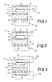
- Fig. 1 there is shown the detecting portion of an electrochemical element (oxygen sensing element) of an electrochemical device in the form of an oxygen sensor according to one embodiment of the present invention.
- the detecting portion is provided at one of opposite longitudinal ends of the electrochemical element.
- This electrochemical element which is indicated at 2 in Fig. 1, is an integral, planar, elongate, laminar structure having a relatively small width, as well known in the art.
- the detecting portion at the above-indicated one longitudinal end of the electrochemical element is operated according to the principle of a concentration cell.
- the electrochemical element 2 indicated above is formed by known laminating techniques.
- the element 2 includes a planar solid electrolyte body 4 made of a suitable solid electrolyte such as zirconia ceramic, which exhibits a high degree of oxygen-ion conductivity at an elevated temperature.
- the planar solid electrolyte body 4 has an air passage 6 formed therein so as to extend in the longitudinal direction. This air passage 6 communicates with the ambient air, at the other longitudinal end of the electrochemical element.
- a similar porous electrode 10 as a reference electrode is formed in contact with an inner surface of the solid electrolyte body 4, such that the reference electrode 10 communicates with the atmosphere which exists within the air passage 6 as a reference gas.
- the outer measuring electrode 8 is covered by a porous protective layer 12 made of alumina, for example, and is thus protected by this layer from direct exposure to an external gas to be measured by the instant electrochemical device (hereinafter referred to as "measurement gas").
- the measuring electrode 8 is exposed to the measurement gas through the porous structure of the protective layer 12.
- the solid electrolyte body 4, and the measuring and reference electrodes 8, 10 formed in contact with the solid electrolyte body 4 cooperate with each other to constitute an electrochemical cell which functions as a concentration cell.
- an electromotive force is induced between the measuring and reference electrodes 8, 10, according to a difference in oxygen partial pressure between the atmospheres with which the electrodes communicate.
- the induced electromotive force is detected by an external voltage measuring means 14.
- a porous inner electrically insulating layer 16 formed of alumina or similar material.
- a solid electrolyte layer 18 which is made of a solid electrolyte material such as zirconia ceramic, as used for the solid electrolyte body 4.
- a protective electrode 20 is embedded in the inner insulating layer 16, such that the electrode 20 is in contact with the surface of the solid electrolyte layer 18 which contacts the insulating layer 16. This protective electrode 20 is electrically connected to the measuring electrode 8 of the electrochemical cell described above.
- the outer surface of the solid electrolyte body 18 is covered by a porous outer electrically insulating layer 22 made of alumina or similar material.
- a porous outer electrically insulating layer 22 made of alumina or similar material.
- This highly dense insulating layer 26 has a heater 24 embedded therein as an integral part thereof.
- the heater 24 is connected to an external power source 28, so that the energized heater 24 heats at least the end portion of the electrochemical element 2 at which the detecting portion is provided, in order to maintain a suitable operating temperature of the detecting portion.
- the electrochemical element 2 described above is constructed such that the first electrically insulating ceramic layer (22, 26) and the second electrically insulating ceramic layer (16) are disposed between the solid electrolyte body 4 of the electrochemical cell and the heater 24, while the solid electrolyte layer 18 is disposed between the first and second electrically insulating ceramic layers, such that the protective electrode 20 electrically connected to the measuring electrode 8 of the electrochemical cell is held in contact with the solid electrolyte layer 18.
- a leak current from the heater 24 is effectively led to the protective electrode 20 through the electrically conductive solid electrolyte layer 18, but is prevented by the inner insulating layer 16 from flowing into the electrochemical cell. Therefore, the instant arrangement avoids an adverse effect of the leak current from the heater 24, on the electromotive force (i.e., output) induced in the electrochemical cell (4, 8, 10) based on an oxygen partial pressure difference between the measurement gas and the reference gas. Accordingly, the accuracy of detection of the measurement gas based on the output of the cell is effectively improved.
- the protective electrode 20 is exposed to the measurement gas or atmosphere through the porous inner insulating layer 16 (second electrically insulating ceramic layer), the electrode 20 is supplied with oxygen ions from the measurement gas. Consequently, a portion of the solid electrolyte layer 18 which contacts the protective electrode 20 is not deteriorated by a flow of the leak current from the heater to the protective electrode 20 through the solid electrolyte layer 18.
- the second electrically insulating ceramic layer 16 provides a sufficient insulating effect even though its thickness is smaller than that of the first electrically insulating ceramic layer 22, 26, since the second ceramic layer 16 is not in direct contact with the heater 24 and is not locally heated.
- the leak current from the heater 24 is effectively led to the protective electrode 20 through the solid electrolyte layer 18, since the electrode 20 is in contact with the layer 18.
- This arrangement does not require the protective electrode 20 to have an increased surface area, even if the surface area of the heater 24 is increased.
- the protective electrode 20 may function with a relatively small surface area contacting the solid electrolyte layer 18, and therefore does not cause inconveniences such as reduction in the strength and durability of the electrochemical element 2, or increase in the cost of manufacture.
- FIG. 2 there is shown another form of the electrochemical element 2 which uses a concentration cell similar to that of the electrochemical element 2 shown in Fig. 1
- this electrochemical element 2 of Fig. 2 is different from the element of Fig. 1, in that the protective electrode 20 is disposed in contact with the solid electrolyte layer 18 such that the electrode 20 is exposed to the air passage 6 and electrically connected to the reference electrode 10 also exposed to the air passage 6.
- Another difference of the instant electrochemical element 2 from that of Fig. 1 lies in that the heater 24 is embedded in the outer insulating layer 22 and electrically connected to a power source in the form of an AC power source 30 (e.g., 10KHz sine wave current).
- the other components of this electrochemical element 2 are identical with the corresponding components of the element 2 of Fig. 1. These corresponding components are identified by the same reference numerals in Figs. 1 and 2, and redundant description of these components will not be provided.
- both the reference electrode 10 of the electrochemical cell and the protective electrode 20 are exposed to the air passage 6, that is, communicate with the same atmosphere, i.e., ambient air as the reference gas. Consequently, there is induced no electromotive force between the two electrodes 10 and 20, due to a difference in the oxygen partial pressure. This results in improvement in the detecting accuracy of the electrochemical element 2.
- the inner electrically insulating layer 16 prevents the leak current from the heater 24 from flowing into the electrochemical cell (4, 8, 10), while the solid electrolyte layer 18 permits the leak current to be effectively led to the protective electrode 20, whereby an error in the output of the electrochemical element 2 due to the leak current is suitably reduced or eliminated.
- the instant electrochemical element 2 does not include a metal layer between the solid electrolyte body 4 of the electrochemical cell and the heater 24, since the protective electrode 20 as a metal layer is disposed within the air passage 6.
- the electrochemical cell and the ceramic layer inner insulating layer 16, solid electrolyte layer 18 and outer insulating layer 22) can be well integrated as a unitary laminar structure having an increased strength.
- the electrochemical element 2 has an electrochemical cell in the form of an electrochemical pumping cell which includes the solid electrolyte body 4, and an outer and an inner pumping electrode 32, 34 formed in contact with the solid electrolyte body 4.
- the measurement gas in the external space is introduced into an internal space 36 to which the inner pumping electrode 34 is exposed, through a pin hole 38 which has a predetermined resistance to diffusion of the measurement gas therethrough.
- the inner pumping cell 34 communicates with the atmosphere which has diffused in the internal space 36.
- a pumping voltage from an external power source 40 is applied between the two pumping electrodes 32, 34 of the pumping cell, so that the atmosphere within the internal space 36 is varied by an pumping action of the pumping cell.
- the measurement of the measurement gas is made based on the pumping current which is determined according to the known principle of polarographic analysis.
- the inner electrically insulating layer 16 is formed on the surface of the solid electrolyte body 4 of the electrochemical pumping cell remote from the outer pumping electrode 32.
- the solid electrolyte layer 18 is formed on the inner insulating layer 16, and the protective electrode 20 is formed on the outer surface of the solid electrolyte layer 18.
- the solid electrolyte layer 18 incorporates the outer electrically insulating layer 22, in which the heater 24 is embedded, such that at least the heat-generating portion of the heater 24 is embedded in the highly dense or gas-tight structure of the solid electrolyte layer 18.
- the protective electrode 20 is electrically connected to the positive electrode 32 of the electrochemical pumping cell, and to the negative terminal of the power source 28 for the heater 24 (more precisely, to the negative lead of the heater 24). Further, the protective electrode 20 is exposed to the atmosphere (measurement gas) to which the outer pumping electrode 32 of the pumping cell is also exposed.
- the inner insulating layer 16 effectively prevents the leak current from the heater 24 from flowing into the electrochemical pumping cell, while the solid electrolyte layer 18 effectively leads the leak current to the protective electrode 20, whereby the adverse effect of the heater leak current is suitably avoided.
- the protective electrode 20 provided on the outer surface of the solid electrolyte layer 18, i.e., on the outer surface of the element 2, effectively eliminates otherwise possible reduction in the strength of the element 2 and increase in the cost of manufacture.
- the dense structure of the solid electrolyte layer 18 of the instant electrochemical element 2 surrounds at least the heat-generating portion of the heater 24, whereby the heated heat-generating portion embedded in the dense layer 18 is protected from diffusion of its metallic material, or deterioration due to exposure to the measurement gas.
- the instant arrangement is advantageous from the standpoint of durability of the heater 24.
- each of the electrochemical elements 2 of Figs. 4 and 5 is characterized by the use of two electrochemical cells, namely, an electrochemical pumping cell and an electrochemical sensing cell.
- the electrochemical pumping cell is constituted by a solid electrolyte body 4a, and an outer and inner pumping electrode 32, 34 formed on the opposite major surfaces of the solid electrolyte body 4a
- the electrochemical sensing cell is constituted by a solid electrolyte body 4b, and a measuring and reference electrode 8, 10 formed on the opposite major surfaces of the solid electrolyte body 4b.
- These two electrochemical cells are electrically insulated from each other by an electrically insulating layer 42 made of alumina or similar material. Between the two cells, there is formed a thin flat space 44 which serves as diffusion-resistance means having a predetermined diffusion resistance.
- a gas inlet aperture 46 is formed in communication with a central portion of the thin flat space 44, so that the measurement gas in the external measurement-gas space is introduced through the aperture 46 into the thin flat space 44.
- the introduced measurement gas diffuses through the thin flat space 44 under the predetermined diffusion resistance, so that the measurement gas contacts the inner pumping electrode 34 and the measuring electrode 8 which are disposed in facing relationship with each other, at an outer portion of the space 44.
- the thin flat space 44 having the predetermined diffusion resistance is formed in the solid electrolyte body 4 such that the space 44 is directly open to the external measurement-gas space.
- the electrochemical pumping cell is constituted by a portion of the solid electrolyte body 4 that defines one of opposite inner surfaces of the flat space 44, and the outer and inner pumping electrodes 32, 34 formed in contact with that portion of the body 4.
- the electrochemical sensing cell is constituted by another portion of the solid electrolyte body 4 that defines the other inner surface of the flat space 44, and the measuring and reference electrodes 8, 10 formed in contact with the above-indicated another portion of the body 4.
- the measurement gas which has diffused into the thin flat space 44 under the predetermined diffusion resistance contacts the inner pumping electrode 34 of the pumping cell and the measuring electrode 8 of the sensing cell, which are disposed at a relatively inner portion of the flat space 44.
- an electromotive force is induced between the measuring and reference electrodes 8, 10 of the oxygen concentration sensing cell, according to the principle of an oxygen concentration cell, based on a difference in oxygen concentration between the measurement gas which has diffused into the flat space 44 under the predetermined diffusion resistance, and the reference gas (ambient air) existing in the air passage 6.
- a pumping current from an external power source 48 is applied between the outer and inner pumping electrodes 32, 34 of the pumping cell, so that an oxygen pumping action is performed so as to control the atmosphere in the flat space 44, adjacent to the inner pumping electrode 34, that is, so that the atmosphere adjacent to the measuring electrode 8 of the oxygen concentration sensing cell is controlled to be a predetermined atmosphere.
- the oxygen concentration of the measurement gas is determined by detecting a pumping current which flows betwen the two pumping electrodes 32, 34.
- the inner electrically insulating layer 16 is interposed between the solid electrolyte layer 18 and the solid electrolyte body 4b of the electrochemical sensing cell, such that the layer 16 partially defines the air passage 6.
- the protective electrode 20 is disposed on the surface of the solid electrolyte layer 18 which is exposed to the air passage 6.
- the outer electrically insulating layer 22 incorporating the heater 24 is embedded in the solid electrolyte layer 18.
- the protective electrode 20 is electrically connected to the inner pumping electrode 34 of the pumping cell, the measuring electrode 8 of the sensing cell, and the negative terminal of the power source 28 for the heater 24.
- the inner insulating layer 16, the solid electrolyte layer 18, and the outer insulating layer 22 having the heater 24 embedded therein are superposed on each other to form an integral laminar structure, as in the element 2 of Fig. 2.
- the protective electrode 20 is disposed on the surface of the solid electrolyte layer 18 which is exposed to the air passage 6.
- the electrode 20 is electrically connected to the reference electrode 10 of the electrochemical sensing cell and the negative terminal of the power source 28 for the heater 24.
- the electrochemical elements 2 shown in Figs. 4 and 5 also have the same advantages as offered on the preceding examples, namely, reduced output error or improved detecting accuracy, elimination of reduced structural strength and increased production cost, avoidance of output inconsistency due to an electromotive force induced between the protective electrode and the sensing cell electrode based on an oxygen concentration difference therebetween, and prevention of deterioration of the solid electrolyte body by the heater leak current.
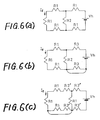
- the equivalent circuit shown in Fig. 6(a) is equivalent to a known electrochemical element wherein a protective electrode is embedded in a solid electrolyte layer, as disclosed in Fig. 3 of JP-A-59-197851.
- the equivalent circuit shown in Fig. 6(b) is equivalent to another type of known electrochemical element wherein a protective electrode is disposed in contact with a solid electrolyte of an electrochemical sensing cell, while a heater is disposed on an electrically insulating layer formed on the solid electrolyte of the cell, as disclosed in Fig. 2 of Laid-open Publication No. 57-196148 (corresponding to U.S. Patent 4,400,260), and in Fig. 4 of the Publication No. 59-197851 identified above.
- the equivalent circuit shown in Fig. 6(c) is equivalent to the electrochemical elements of the electrochemical device of the present invention as illustrated above.
- the calculated values I l of the heater leak current are 960 ⁇ A in the circuit of Fig. 6(a), 0.98 ⁇ A in the circuit of Fig. 6(b), and 0.06 ⁇ A in the circuit of Fig. 6(c). It follows from the above that the leak current values in the equivalent circuits of Figs. 6(b) and 6(c) are both well within a practically permissible range of tolerances.
- the known electrochemical element represented by the equivalent circuit of Fig. 6(a) suffers from an excessively large amount of the heater leak current. This means that the known arrangement of Fig. 6(a) cannot expect the protective electrode alone to provide a sufficient insulating effect.
- the heater leak current Il in the known electrochemical element represented by the circuit of Fig. 6(b) is sufficiently reduced, it is necessary to electrically insulate the protective electrode (i.e., power supply circuit for the heater) and a measuring circuit of the electrochemical cell, relative to each other. This electrical insulation is technically difficult. In the absence of the electrical insulation, there may arise a loop current due to an electromotive force which would be induced between the protective electrode and one of the electrodes of the electrochemical cell. If the electromotive force is 0.5V while the resistance (R1) of the solid electrolyte is 100 ⁇ , for example, the loop current amounts to 5mA, which results in reducing the detecting accuracy of the electrochemical element.
- the heater leak current is reduced to a sufficiently low level, while at the same time the loop current is held sufficiently low. If the resistance R3 ⁇ of the insulating ceramic layer is 100K ⁇ and the electromotive force is 0.5V, for example, the loop current is as low as 5 ⁇ A.
- the solid electrolyte bodies (4, 4a, 4b), and the solid electrolyte layer (18) adjacent to the heater 24 are preferably formed principally of an oxygen-ion conductive solid electrolyte material such as zirconia ceramic.
- the solid electrolyte bodies and layer may be formed of other oxygen-ion conductive solid electrolyte materials such as SrCeO3, or a solid solution of Bi2O3 and rare earth oxides.
- the electrochemical element is adapted to determine the concentration of a component other than oxygen, it is obvious that other solid electrolyte materials are selected depending upon the component to be measured.
- the major component of these insulating layers may consist of other ceramic materials such as borosilicate glass, mullite, steatite, forsterite, cordierite, and zircon.
- the protective electrode (20) is preferably formed of a material whose major component consists of a metal selected from the platinum group which includes platinum, palladium, rhodium, iridium, ruthenium and osmium, like the measuring electrode (8), reference electrode (10), outer pumping electrode (32), inner pumping electrode (34), and heater (24).
- a metal selected from the platinum group which includes platinum, palladium, rhodium, iridium, ruthenium and osmium, like the measuring electrode (8), reference electrode (10), outer pumping electrode (32), inner pumping electrode (34), and heater (24).
- the powdered metal for the electrodes be mixed with a finely divided powder of a suitable ceramic material such as zirconia or alumina.
- the illustrated electrochemical elements have a single heating portion (heater) on one side of the electrochemical cell (or on one side of the laminar structure of the two electrochemical cells), it is possible that two or more heating portions are provided on the opposite sides of the electrochemical cell or the laminar structure of the two cells, or between the two cells.
- the principle of the present invention may apply to a sensor, detector or controller adapted to determine the concentration of components of a fluid other than oxygen, such as nitrogen, carbon dioxide or hydrogen, which involve an electrode reaction.
Landscapes
- Chemical & Material Sciences (AREA)
- Life Sciences & Earth Sciences (AREA)
- Health & Medical Sciences (AREA)
- Physics & Mathematics (AREA)
- Chemical Kinetics & Catalysis (AREA)
- Electrochemistry (AREA)
- Molecular Biology (AREA)
- Analytical Chemistry (AREA)
- Biochemistry (AREA)
- General Health & Medical Sciences (AREA)
- General Physics & Mathematics (AREA)
- Immunology (AREA)
- Pathology (AREA)
- Measuring Oxygen Concentration In Cells (AREA)
Claims (6)
- Dispositif électrochimique comportant un élément électrochimique ayant une structure laminaire intégralement formée, comprenant :
au moins une cellule électrochimique comportant un premier électrolyte solide (4 ; 4a, 4b) et au moins une paire d'électrodes (8, 10 ; 30, 34) qui sont formées en contact avec ledit premier électrolyte solide ;
au moins une portion chauffante comportant un second électrolyte solide (18), une première couche isolante en céramique poreuse (22) formée en contact avec ledit second électrolyte solide, et un réchauffeur (24) électriquement isolé dudit second électrolyte solide par ladite première couche de céramique électriquement isolante ;
une seconde couche électriquement isolante en céramique poreuse (16) interposée entre le premier électrolyte solide (4 ; 4a, 4b) de ladite au moins une cellule électrochimique et ledit second électrolyte solide (18) de ladite au moins une portion chauffante afin d'isoler électriquement lesdits premier et second électrolytes solides l'un de l'autre ; et
une électrode protectrice (20) formée en contact avec ledit électrolyte solide (18) de ladite portion chauffante et électriquement connectée à au moins l'une de ladite paire d'électrodes (8, 10; 32, 34) de ladite cellule électrochimique, ladite électrode protectrice (20) étant électriquement isolée par ladite seconde couche isolante (16) afin d'empêcher sa connexion électrique à toute électrode de ladite cellule ou desdites cellules par lesdits électrolytes solides et au moins une portion de ladite électrode protectrice (20) étant sensiblement exposée à un fluide gazeux. - Dispositif électrochimique selon la revendication 1 où ladite électrode protectrice (20) est électriquement connectée à une borne de tension négative dudit réchauffeur (24).
- Dispositif électrochimique selon la revendication 1 ou 2, où ladite électrode protectrice (20) et ladite électrode à laquelle elle est connectée sont exposées sensiblement au même fluide gazeux.
- Dispositif électrochimique selon l'une quelconque des revendications 1 à 3, où ledit second électrolyte solide (18) a une structure sensiblement étanche aux gaz qui entoure au moins une portion génératrice de chaleur dudit réchauffeur.
- Dispositif électrochimique selon l'une quelconque des revendications 1 à 4, ayant un certain nombre de cellules électrochimiques comprenant une cellule de pompage électrochimique ayant une paire d'électrodes de pompage (32, 34) et une cellule électrochimique de détection ayant une électrode de mesure (8) et une électrode de référence (10), et où ladite électrode protectrice (20) est électriquement connectée à l'une de ladite paire d'électrodes de pompage de ladite cellule de pompage et ladite électrode de mesure de ladite cellule de détection, ladite électrode de pompage et ladite électrode de mesure étant exposées sensiblement au même fluide gazeux.
- Dispositif électrochimique selon l'une quelconque des revendications 1 à 4, ayant un certain nombre de cellules électrochimiques comprenant une cellule de pompage électrochimique et une cellule de détection électrochimique ayant une électrode de référence (10) et où ladite électrode protectrice (20) est électriquement connectée à ladite électrode de référence de ladite cellule de détection.
Applications Claiming Priority (2)
| Application Number | Priority Date | Filing Date | Title |
|---|---|---|---|
| JP48245/87 | 1987-03-03 | ||
| JP62048245A JPH0684950B2 (ja) | 1987-03-03 | 1987-03-03 | 電気化学的装置 |
Publications (3)
| Publication Number | Publication Date |
|---|---|
| EP0281378A2 EP0281378A2 (fr) | 1988-09-07 |
| EP0281378A3 EP0281378A3 (en) | 1989-11-29 |
| EP0281378B1 true EP0281378B1 (fr) | 1993-09-01 |
Family
ID=12798057
Family Applications (1)
| Application Number | Title | Priority Date | Filing Date |
|---|---|---|---|
| EP88301817A Expired - Lifetime EP0281378B1 (fr) | 1987-03-03 | 1988-03-02 | Dispositif électrochimique avec élément chauffant |
Country Status (4)
| Country | Link |
|---|---|
| US (1) | US4814059A (fr) |
| EP (1) | EP0281378B1 (fr) |
| JP (1) | JPH0684950B2 (fr) |
| DE (1) | DE3883562T2 (fr) |
Families Citing this family (28)
| Publication number | Priority date | Publication date | Assignee | Title |
|---|---|---|---|---|
| JPH0786498B2 (ja) * | 1988-06-02 | 1995-09-20 | 日本碍子株式会社 | 加熱型酸素センサ |
| JPH09156427A (ja) * | 1995-12-06 | 1997-06-17 | Koji Yamao | 自動車用荷物台 |
| JP3546590B2 (ja) * | 1996-04-12 | 2004-07-28 | 株式会社デンソー | 空燃比センサー |
| JP3841957B2 (ja) * | 1998-07-06 | 2006-11-08 | 本田技研工業株式会社 | 酸素センサ |
| DE19833453C2 (de) * | 1998-07-24 | 2000-06-15 | Siemens Ag | Vorrichtung und Betriebsverfahren an/in geheizten Gassensoren zur Minimierung von Leckstrom-Einflüssen |
| DE19835766C2 (de) * | 1998-08-07 | 2003-07-03 | Bosch Gmbh Robert | Anordnung zum Beschalten eines elektrochemischen Sensors |
| DE19857468A1 (de) * | 1998-12-14 | 2000-06-15 | Bosch Gmbh Robert | Elektrochemischer Meßfühler für die Bestimmung von Gaskonzentrationen in Gasen |
| US6411110B1 (en) * | 1999-08-17 | 2002-06-25 | Micron Technology, Inc. | Apparatuses and methods for determining if protective coatings on semiconductor substrate holding devices have been compromised |
| JP2001124723A (ja) * | 1999-10-26 | 2001-05-11 | Ngk Spark Plug Co Ltd | ヒータ付き酸素センサ及びその製造方法 |
| JP4632506B2 (ja) | 2000-02-29 | 2011-02-16 | 株式会社豊田中央研究所 | NOxガス検出装置 |
| JP4229565B2 (ja) * | 2000-02-29 | 2009-02-25 | 株式会社豊田中央研究所 | NOxセンサ |
| JP2001281206A (ja) * | 2000-03-29 | 2001-10-10 | Kyocera Corp | 検出素子 |
| DE10058643A1 (de) * | 2000-11-25 | 2002-06-06 | Bosch Gmbh Robert | Heizeinrichtung |
| DE10114186C2 (de) * | 2001-03-23 | 2003-10-30 | Bosch Gmbh Robert | Sensorelement |
| DE10115872A1 (de) * | 2001-03-30 | 2002-10-17 | Bosch Gmbh Robert | Gassensor |
| DE10133160C1 (de) * | 2001-07-07 | 2003-01-30 | Bosch Gmbh Robert | Sensorelement mit leitfähiger Abschirmung |
| DE10157736B4 (de) * | 2001-11-24 | 2004-04-15 | Robert Bosch Gmbh | Sensorelement für einen elektrochemischen Meßfühler |
| DE10157734B4 (de) * | 2001-11-24 | 2004-04-29 | Robert Bosch Gmbh | Gasmeßfühler |
| DE10163942A1 (de) * | 2001-12-22 | 2003-07-10 | Bosch Gmbh Robert | Abgassonde |
| US6837982B2 (en) | 2002-01-25 | 2005-01-04 | Northwest Aluminum Technologies | Maintaining molten salt electrolyte concentration in aluminum-producing electrolytic cell |
| JP4084593B2 (ja) * | 2002-04-24 | 2008-04-30 | 京セラ株式会社 | 酸素センサ素子 |
| DE10225149A1 (de) * | 2002-06-06 | 2004-01-15 | Robert Bosch Gmbh | Sensorelement |
| DE10339967A1 (de) | 2002-08-30 | 2004-04-15 | Denso Corp., Kariya | Mehrschicht-Gassensorelement |
| JP4050593B2 (ja) * | 2002-11-01 | 2008-02-20 | 日本特殊陶業株式会社 | ガスセンサ素子及びこれを用いたガスセンサ |
| DE102006014681A1 (de) * | 2006-03-28 | 2007-10-04 | Robert Bosch Gmbh | Gassensor |
| DE102008001223A1 (de) * | 2008-04-17 | 2009-10-22 | Robert Bosch Gmbh | Beheizte Sprungsonde mit vereinfachter elektrischer Kontaktierung |
| CN102132153B (zh) * | 2008-08-25 | 2014-08-20 | Nxp股份有限公司 | 减小电子设备中的电容性充电 |
| DE102013219531A1 (de) * | 2013-09-27 | 2015-04-02 | Continental Automotive Gmbh | Sensor zur Erfassung eines Gases in einer Umgebung des Sensors |
Family Cites Families (6)
| Publication number | Priority date | Publication date | Assignee | Title |
|---|---|---|---|---|
| DE3120159A1 (de) * | 1981-05-21 | 1982-12-09 | Bosch Gmbh Robert | Elektrochemischer messfuehler fuer die bestimmung des sauerstoffgehaltes in gasen |
| JPS59197851A (ja) * | 1983-04-26 | 1984-11-09 | Ngk Insulators Ltd | 電気化学的素子および装置 |
| JPS60108745A (ja) * | 1983-11-18 | 1985-06-14 | Ngk Insulators Ltd | 電気化学的装置 |
| JPS60173461A (ja) * | 1984-02-20 | 1985-09-06 | Nissan Motor Co Ltd | 酸素センサ |
| JPS60239664A (ja) * | 1984-05-14 | 1985-11-28 | Nissan Motor Co Ltd | 酸素センサの加熱装置 |
| JPH0646189B2 (ja) * | 1985-01-25 | 1994-06-15 | 株式会社日立製作所 | 酸素濃度センサ |
-
1987
- 1987-03-03 JP JP62048245A patent/JPH0684950B2/ja not_active Expired - Lifetime
-
1988
- 1988-03-01 US US07/162,489 patent/US4814059A/en not_active Expired - Lifetime
- 1988-03-02 DE DE88301817T patent/DE3883562T2/de not_active Expired - Lifetime
- 1988-03-02 EP EP88301817A patent/EP0281378B1/fr not_active Expired - Lifetime
Also Published As
| Publication number | Publication date |
|---|---|
| EP0281378A3 (en) | 1989-11-29 |
| DE3883562T2 (de) | 1994-03-17 |
| EP0281378A2 (fr) | 1988-09-07 |
| JPS63214663A (ja) | 1988-09-07 |
| DE3883562D1 (de) | 1993-10-07 |
| JPH0684950B2 (ja) | 1994-10-26 |
| US4814059A (en) | 1989-03-21 |
Similar Documents
| Publication | Publication Date | Title |
|---|---|---|
| EP0281378B1 (fr) | Dispositif électrochimique avec élément chauffant | |
| EP0188900B1 (fr) | Dispositif électrochimique | |
| EP0144185B1 (fr) | Dispositif électrochimique | |
| EP0172746B1 (fr) | Dispositif électrochimique | |
| JP3665333B2 (ja) | ガス混合気のガス成分及び/又はガス濃度検出用センサ装置 | |
| EP0310206B1 (fr) | Dispositif électrochimique | |
| US6287439B1 (en) | Gas sensor | |
| JP3871497B2 (ja) | ガスセンサ | |
| US4902400A (en) | Gas sensing element | |
| US4639305A (en) | Electrochemical element | |
| US4909922A (en) | Heater-built-in oxygen sensor | |
| US6579435B2 (en) | Gas sensor | |
| EP0869356B1 (fr) | Capteur de NOx | |
| EP0987548B1 (fr) | Capteur de gaz | |
| EP0227257B1 (fr) | Dispositif électrochimique | |
| US4400260A (en) | Shielded, heated electrochemical gas sensor | |
| US5028309A (en) | Electrochemical device incorporating means for preventing reduction of solid electrolyte and insulating ceramics due to heater current leakage | |
| JP2003517605A (ja) | 電気化学的測定センサ | |
| US6346178B1 (en) | Simplified wide range air fuel ratio sensor | |
| JP3771569B2 (ja) | NOxセンサ | |
| US6589409B2 (en) | Multilayered gas sensing element employable in an exhaust system of an internal combustion engine | |
| US20020108870A1 (en) | Nitrogen oxide sensor and method for detecting nitrogen oxides | |
| US4455214A (en) | Thin-film sensor apparatus | |
| KR20220028947A (ko) | 바이어스전압을 이용한 혼합전위차식 질소산화물 센서 | |
| JPS62190461A (ja) | 空燃比センサの活性化検出装置 |
Legal Events
| Date | Code | Title | Description |
|---|---|---|---|
| PUAI | Public reference made under article 153(3) epc to a published international application that has entered the european phase |
Free format text: ORIGINAL CODE: 0009012 |
|
| 17P | Request for examination filed |
Effective date: 19880416 |
|
| AK | Designated contracting states |
Kind code of ref document: A2 Designated state(s): DE FR GB |
|
| PUAL | Search report despatched |
Free format text: ORIGINAL CODE: 0009013 |
|
| AK | Designated contracting states |
Kind code of ref document: A3 Designated state(s): DE FR GB |
|
| 17Q | First examination report despatched |
Effective date: 19910619 |
|
| GRAA | (expected) grant |
Free format text: ORIGINAL CODE: 0009210 |
|
| AK | Designated contracting states |
Kind code of ref document: B1 Designated state(s): DE FR GB |
|
| REF | Corresponds to: |
Ref document number: 3883562 Country of ref document: DE Date of ref document: 19931007 |
|
| ET | Fr: translation filed | ||
| PLBE | No opposition filed within time limit |
Free format text: ORIGINAL CODE: 0009261 |
|
| STAA | Information on the status of an ep patent application or granted ep patent |
Free format text: STATUS: NO OPPOSITION FILED WITHIN TIME LIMIT |
|
| 26N | No opposition filed | ||
| REG | Reference to a national code |
Ref country code: GB Ref legal event code: IF02 |
|
| PGFP | Annual fee paid to national office [announced via postgrant information from national office to epo] |
Ref country code: GB Payment date: 20070202 Year of fee payment: 20 |
|
| PGFP | Annual fee paid to national office [announced via postgrant information from national office to epo] |
Ref country code: DE Payment date: 20070330 Year of fee payment: 20 |
|
| REG | Reference to a national code |
Ref country code: GB Ref legal event code: PE20 |
|
| PGFP | Annual fee paid to national office [announced via postgrant information from national office to epo] |
Ref country code: FR Payment date: 20070301 Year of fee payment: 20 |
|
| PG25 | Lapsed in a contracting state [announced via postgrant information from national office to epo] |
Ref country code: GB Free format text: LAPSE BECAUSE OF EXPIRATION OF PROTECTION Effective date: 20080301 |