EP0281386A2 - Système téléphonique à fourche - Google Patents
Système téléphonique à fourche Download PDFInfo
- Publication number
- EP0281386A2 EP0281386A2 EP88301832A EP88301832A EP0281386A2 EP 0281386 A2 EP0281386 A2 EP 0281386A2 EP 88301832 A EP88301832 A EP 88301832A EP 88301832 A EP88301832 A EP 88301832A EP 0281386 A2 EP0281386 A2 EP 0281386A2
- Authority
- EP
- European Patent Office
- Prior art keywords
- telephones
- telephone
- priority
- telephone system
- branched
- Prior art date
- Legal status (The legal status is an assumption and is not a legal conclusion. Google has not performed a legal analysis and makes no representation as to the accuracy of the status listed.)
- Granted
Links
Images
Classifications
-
- H—ELECTRICITY
- H04—ELECTRIC COMMUNICATION TECHNIQUE
- H04M—TELEPHONIC COMMUNICATION
- H04M1/00—Substation equipment, e.g. for use by subscribers
- H04M1/71—Substation extension arrangements
- H04M1/715—Substation extension arrangements using two or more extensions per line
-
- H—ELECTRICITY
- H04—ELECTRIC COMMUNICATION TECHNIQUE
- H04M—TELEPHONIC COMMUNICATION
- H04M1/00—Substation equipment, e.g. for use by subscribers
- H04M1/72—Mobile telephones; Cordless telephones, i.e. devices for establishing wireless links to base stations without route selection
- H04M1/725—Cordless telephones
Definitions
- the present invention relates to a branched telephone system in which a plurality of telephones are connected to a single subscriber line or to single radio equipment and, more particularly, to a branched telephone system capable of automatically cancelling a priority set condition in which particular one of a plurality of telephones is usable.
- two or more telephones are simply connected in parallel with no special control provided over them. In such a configuration, all the telephones share entirely the same functions and, therefore, it is impossible to give priority to desired one of the telephones over the others or to positively invalidate the latter.
- two independent telephones may be connected to single radio equipment which is mounted on a vehicle and individually disposed in the vicinity of a front seat and a rear seat of the vehicle. It often occurs with such a vehicle-mounted telephone system that an occupant in the vehicle desires to invalidate one of the two telephones. For example, a person originated a call on the telephone near the rear sheet may desire to keep the telephone number of the other party and the contents of communication from the driver.
- an object of the present invention to provide a branched telephone system capable of establishing a priority set condition in which the communication function of particular one of a plurality of telephones is validated to prevent the other telephones from being used.
- a branched telephone system having a plurality of telephones which are connected to a single subscriber line or to single radio equipment of the present invention comprises priority setting means for establishing a priority set condition in which particular one of the telephones is usable with the other telephone or telephones being invalidated in function, and priority cancelling means for cancelling the priority set condition by detecting a change in a hook condition of any of the telephones to which priority is given over the other or others.
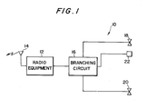
- a branched telephone system embodying the present invention is shown and generally designated by the reference numeral 10.
- the system 10 is made up of radio equipment 12 having an antenna 14, a branching circuit 16 provided with priority setting means, a master telephone 18, and a servant telephone 20.
- the telephones 18 and 20 are each connected to the radio equipment 12 via the branching circuit 16.
- a switch unit 22 located in the vicinity of the master telephone 18 is connected to the branching circuit 16 and accessible for setting a priority set condition.
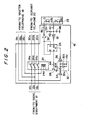
- Fig. 2 shows a specific construction of the branching circuit 16 and that of the switch unit 22.
- a speech signal and control signal line 12b and a power supply line 12c of the radio equipment 12 are directly connected to, respectively, a speech signal and control signal line 18b and a power supply line 18c of the master telephone 18.
- a hook signal line 18a of the master telephone 18 is held in direct connection with a hook signal line 12a of the radio equipment 12.
- a hook signal line 20a, a speech signal and control signal line 20b and a power supply line 20c of the servant telephone 20 are connected to, respectively, the hook signal line 20a, a speech signal and control signal line 12b and power supply line 12c of the radio equipment 12 via a relay 24.
- a flip-flop 26 is connected between the switch unit 22 and the relay 24 while a transistor 28 is connected between the relay 24 and the flip-flop 26.
- the output Q of the flip-flop 26 is maintained low level so that the transistor 28 remains non-conductive. In this condition, no current flows through the winding 24d of the relay 24 to hold contacts 24a, 24b and 24c of the relay 24 closed, so that the servant telephone 20 is connected to the radio equipment 12 and usable in the same manner as the master telephone 18.
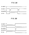
- the output Q of the flip-flop 26 becomes high level, as shown in Fig. 3A.
- the transistor 28 is turned on to cause a current to flow through the winding 24d of the relay 24, whereby the relay contacts 24a, 24b and 24c are opened. Consequently, the servant telephone 20 is electrically isolated from the radio equipment 12 and, therefore, unusable while the master telephone 18 alone is usable.
- the output Q of the flip-flop 26 is inverted to low level restoring the servant telephone 20 to the usable condition.
- a light emitting diode 22b included in the switch unit 22 is adapted to display the state of the flip-flop 26 so that a person may see if the servant telephone 20 is usable through the switch unit 22.
- a differentiator 30 is made up of a capacitor 30a, a resistor 30b and a diode 30c. When a change of the hook signal from low level to high level (see Fig. 3B) is detected by the capacitor 30a and resistor 30b, a reset signal is fed from the differentiator 30 to the flip-flop 26 to thereby reset the output Q to low level.
- the differentiator 30 detects the resulting change of the hook signal from low level to high level, resetting the flip-flop 26. As a result, the output Q of the flip-flop 26 becomes low level to close the contacts 24a, 24b and 24c of the relay 24 again, whereby the priority given to the main telephone 18 is cancelled.
- the reference numerals 32, 34 and 36 designate inverters
- the reference numerals 40, 42, 44 and 46 designate resistors
- the reference numeral 48 designates a capacitor.
- the present invention provides a branched telephone system with a capability of automatically cancelling a priority set condition. Specifically, the system of the invention automatically cancels a priority set condition by referencing the hook state of a telephone to which priority is given, preventing various undesirable occurrences ascribable to an inadvertent failure of cancellation.
- the present invention is applicable to telephone systems other than a vehicle-mounted telephone system shown and described, and telephone systems having more than two telephones.
- the branching circuit and switch unit may be implemented with any known arrangement in place of the circuitry shown in Fig. 2.
Landscapes
- Engineering & Computer Science (AREA)
- Signal Processing (AREA)
- Computer Networks & Wireless Communication (AREA)
- Mobile Radio Communication Systems (AREA)
- Telephone Function (AREA)
Applications Claiming Priority (2)
| Application Number | Priority Date | Filing Date | Title |
|---|---|---|---|
| JP51282/87 | 1987-03-05 | ||
| JP62051282A JPS63217758A (ja) | 1987-03-05 | 1987-03-05 | 分岐電話機 |
Publications (3)
| Publication Number | Publication Date |
|---|---|
| EP0281386A2 true EP0281386A2 (fr) | 1988-09-07 |
| EP0281386A3 EP0281386A3 (en) | 1990-12-05 |
| EP0281386B1 EP0281386B1 (fr) | 1995-02-08 |
Family
ID=12882578
Family Applications (1)
| Application Number | Title | Priority Date | Filing Date |
|---|---|---|---|
| EP88301832A Expired - Lifetime EP0281386B1 (fr) | 1987-03-05 | 1988-03-02 | Système téléphonique à fourche |
Country Status (6)
| Country | Link |
|---|---|
| US (1) | US5022068A (fr) |
| EP (1) | EP0281386B1 (fr) |
| JP (1) | JPS63217758A (fr) |
| KR (1) | KR920001412B1 (fr) |
| AU (1) | AU622857B2 (fr) |
| CA (1) | CA1283231C (fr) |
Cited By (1)
| Publication number | Priority date | Publication date | Assignee | Title |
|---|---|---|---|---|
| GB2266430A (en) * | 1992-04-13 | 1993-10-27 | Clive Richard Harris | Call connection priority designator |
Families Citing this family (5)
| Publication number | Priority date | Publication date | Assignee | Title |
|---|---|---|---|---|
| US5444772A (en) * | 1994-05-11 | 1995-08-22 | Coker; Elzie L. | Telephone line lockout device |
| US5553126A (en) * | 1995-01-20 | 1996-09-03 | Gte Laboratories Incorporated | Secure anti-jamming wireless party line |
| KR100374340B1 (ko) * | 1996-04-03 | 2003-05-17 | 삼성전자주식회사 | 가정용으로 이용가능한 메시지대기전화기 |
| US5978469A (en) * | 1997-01-21 | 1999-11-02 | U S West, Inc. | Apparatus for telephone extension control |
| JP3750642B2 (ja) * | 2002-08-30 | 2006-03-01 | ブラザー工業株式会社 | 通信システム |
Family Cites Families (21)
| Publication number | Priority date | Publication date | Assignee | Title |
|---|---|---|---|---|
| US3435151A (en) * | 1965-12-28 | 1969-03-25 | Int Standard Electric Corp | Arrangement of branched telephone subsets |
| JPS50115906A (fr) * | 1974-02-22 | 1975-09-10 | ||
| US4000375A (en) * | 1975-02-20 | 1976-12-28 | Hachishiro Kawamura | Automatic call transfer circuit for a plurality of telephones |
| US4075434A (en) * | 1976-03-25 | 1978-02-21 | San/Bar Corporation | Key telephone privacy exclusion apparatus |
| JPS54154202A (en) * | 1978-05-26 | 1979-12-05 | Nec Corp | Talking protective circuit for multi-telephone |
| NL7809628A (nl) * | 1978-09-21 | 1980-03-25 | Nederlanden Staat | Schakeling voor multipel aangesloten telefoontoestel- len. |
| US4218590A (en) * | 1979-01-29 | 1980-08-19 | Crest Industries, Inc. | Key telephone system having automatic exclusion circuit for line privacy |
| JPS57190450A (en) * | 1981-05-19 | 1982-11-24 | Meisei Electric Co Ltd | Privacy system for push-button dial telephone set |
| JPS59178851A (ja) * | 1983-03-30 | 1984-10-11 | Toshiba Corp | 電話機回路 |
| US4654655A (en) * | 1984-03-02 | 1987-03-31 | Motorola, Inc. | Multi-user serial data bus |
| US4640987A (en) * | 1984-04-23 | 1987-02-03 | Keizo Tsukada | Cordless telephone |
| JPS60242738A (ja) * | 1984-05-17 | 1985-12-02 | Sony Corp | コ−ドレステレホン |
| ES282513Y (es) * | 1984-11-12 | 1986-10-01 | Amper, S.A. | Dispositivo exclusor para telefonos instalados en paralelo |
| DE3504046A1 (de) * | 1985-02-04 | 1986-08-14 | ELMEG GmbH Kommunikationstechnik, 3150 Peine | Schaltung zum anschalten von zwei fernsprechendeinrichtungen an eine gemeinsame anschlussleitung |
| DE3524523A1 (de) * | 1985-07-05 | 1987-01-15 | Elmeg Kommunikationstech | Schaltung zum im wesentlichen gleichberechtigten anschalten mindestens zweier fernsprechendeinrichtungen an eine gemeinsame leitung |
| JPS6277727A (ja) * | 1985-09-30 | 1987-04-09 | Nec Corp | コ−ドレス電話機用回線切替回路 |
| US4718080A (en) * | 1985-12-16 | 1988-01-05 | Serrano Arthur L | Microprocessor controlled interface for cellular system |
| US4745632A (en) * | 1985-12-27 | 1988-05-17 | Duffy Anthony G | Wireless mobile telephone communication system |
| US4747128A (en) * | 1986-05-22 | 1988-05-24 | Chan Kwok Leung | Telephone privacy protector |
| FR2601537B1 (fr) * | 1986-07-11 | 1994-03-25 | Lepaillier Patrick | Installation telephonique a une ligne et plusieurs postes recepteurs |
| US4748685A (en) * | 1986-10-10 | 1988-05-31 | Motorola, Inc. | Mobile radio communications system |
-
1987
- 1987-03-05 JP JP62051282A patent/JPS63217758A/ja active Granted
-
1988
- 1988-03-02 EP EP88301832A patent/EP0281386B1/fr not_active Expired - Lifetime
- 1988-03-02 US US07/162,878 patent/US5022068A/en not_active Expired - Fee Related
- 1988-03-04 CA CA000560555A patent/CA1283231C/fr not_active Expired - Lifetime
- 1988-03-05 KR KR1019880002301A patent/KR920001412B1/ko not_active Expired
- 1988-03-07 AU AU12742/88A patent/AU622857B2/en not_active Ceased
Cited By (2)
| Publication number | Priority date | Publication date | Assignee | Title |
|---|---|---|---|---|
| GB2266430A (en) * | 1992-04-13 | 1993-10-27 | Clive Richard Harris | Call connection priority designator |
| GB2266430B (en) * | 1992-04-13 | 1996-02-28 | Clive Richard Harris | Call connection priority designator |
Also Published As
| Publication number | Publication date |
|---|---|
| CA1283231C (fr) | 1991-04-16 |
| EP0281386B1 (fr) | 1995-02-08 |
| US5022068A (en) | 1991-06-04 |
| JPS63217758A (ja) | 1988-09-09 |
| AU1274288A (en) | 1988-09-08 |
| JPH055421B2 (fr) | 1993-01-22 |
| KR880012061A (ko) | 1988-11-03 |
| EP0281386A3 (en) | 1990-12-05 |
| AU622857B2 (en) | 1992-04-30 |
| KR920001412B1 (ko) | 1992-02-13 |
Similar Documents
| Publication | Publication Date | Title |
|---|---|---|
| WO1998034387A3 (fr) | Indicateur recepteur d'appels telephoniques | |
| GB2209637A (en) | Power source control device in car telephone mobile station system | |
| US5022068A (en) | Branched telephone system | |
| EP0689330B1 (fr) | Appareil téléphonique capable de traiter une information d'identification d'appel | |
| US4485273A (en) | Intercom adapter for telephones | |
| EP0338834B1 (fr) | Terminal téléphonique mobile avec fonction de libération de la connexion | |
| US4776007A (en) | Solid state trunk circuit | |
| US3865992A (en) | Electronically controlled ring-trap circuit | |
| US4562308A (en) | Subscriber connection circuit comprising feed resistors which can be bridged in low-ohmic fashion and an indication circuit which effects different indications | |
| JP2001511625A (ja) | セキュリティ・システムのアラーム・パネル | |
| EP0366991A2 (fr) | Méthode et dispositif pour garder faible la puissance absorbée par un circuit d'interface téléphonique, dans l'état 'boucle ouverte' de la ligne téléphonique | |
| US4679228A (en) | Speakerphone sensing circuit | |
| US3193621A (en) | Telephone line finder | |
| JP2668688B2 (ja) | 通信システムの端末装置 | |
| KR930010276B1 (ko) | 키폰시스템의 겸용 가입자회로 | |
| US3824348A (en) | Status indication circuit for shared telephone equipment | |
| JPH0410299B2 (fr) | ||
| US3824350A (en) | Access circuit for shared telephone equipment | |
| JPS6486735A (en) | Communication equipment | |
| JPS5866486A (ja) | 局線地気検出方式 | |
| KR970056572A (ko) | 회선자동선택장치 및 그 방법 | |
| JPS6084032A (ja) | 自動車電話装置 | |
| JPS56128089A (en) | Hooking detection system of push-button telephone set | |
| JPH0237741B2 (fr) | ||
| JP2003032393A (ja) | 電話端末ダイアル信号中継装置 |
Legal Events
| Date | Code | Title | Description |
|---|---|---|---|
| PUAI | Public reference made under article 153(3) epc to a published international application that has entered the european phase |
Free format text: ORIGINAL CODE: 0009012 |
|
| 17P | Request for examination filed |
Effective date: 19880324 |
|
| AK | Designated contracting states |
Kind code of ref document: A2 Designated state(s): GB NL SE |
|
| PUAL | Search report despatched |
Free format text: ORIGINAL CODE: 0009013 |
|
| AK | Designated contracting states |
Kind code of ref document: A3 Designated state(s): GB NL SE |
|
| 17Q | First examination report despatched |
Effective date: 19930510 |
|
| GRAA | (expected) grant |
Free format text: ORIGINAL CODE: 0009210 |
|
| AK | Designated contracting states |
Kind code of ref document: B1 Designated state(s): GB NL SE |
|
| PLBE | No opposition filed within time limit |
Free format text: ORIGINAL CODE: 0009261 |
|
| STAA | Information on the status of an ep patent application or granted ep patent |
Free format text: STATUS: NO OPPOSITION FILED WITHIN TIME LIMIT |
|
| 26N | No opposition filed | ||
| PGFP | Annual fee paid to national office [announced via postgrant information from national office to epo] |
Ref country code: NL Payment date: 19970331 Year of fee payment: 10 |
|
| PGFP | Annual fee paid to national office [announced via postgrant information from national office to epo] |
Ref country code: GB Payment date: 19980216 Year of fee payment: 11 |
|
| PGFP | Annual fee paid to national office [announced via postgrant information from national office to epo] |
Ref country code: SE Payment date: 19980305 Year of fee payment: 11 |
|
| PG25 | Lapsed in a contracting state [announced via postgrant information from national office to epo] |
Ref country code: NL Free format text: LAPSE BECAUSE OF NON-PAYMENT OF DUE FEES Effective date: 19981001 |
|
| NLV4 | Nl: lapsed or anulled due to non-payment of the annual fee |
Effective date: 19981001 |
|
| PG25 | Lapsed in a contracting state [announced via postgrant information from national office to epo] |
Ref country code: GB Free format text: LAPSE BECAUSE OF NON-PAYMENT OF DUE FEES Effective date: 19990302 |
|
| PG25 | Lapsed in a contracting state [announced via postgrant information from national office to epo] |
Ref country code: SE Free format text: LAPSE BECAUSE OF NON-PAYMENT OF DUE FEES Effective date: 19990303 |
|
| GBPC | Gb: european patent ceased through non-payment of renewal fee |
Effective date: 19990302 |
|
| EUG | Se: european patent has lapsed |
Ref document number: 88301832.7 |
|
| EUG | Se: european patent has lapsed |
Ref document number: 88301832.7 |