EP0281657B1 - Falschdrall-Kräuselmaschine - Google Patents
Falschdrall-Kräuselmaschine Download PDFInfo
- Publication number
- EP0281657B1 EP0281657B1 EP19870103605 EP87103605A EP0281657B1 EP 0281657 B1 EP0281657 B1 EP 0281657B1 EP 19870103605 EP19870103605 EP 19870103605 EP 87103605 A EP87103605 A EP 87103605A EP 0281657 B1 EP0281657 B1 EP 0281657B1
- Authority
- EP
- European Patent Office
- Prior art keywords
- yarn
- heater
- false twisting
- feed rollers
- less
- Prior art date
- Legal status (The legal status is an assumption and is not a legal conclusion. Google has not performed a legal analysis and makes no representation as to the accuracy of the status listed.)
- Expired
Links
- 238000002788 crimping Methods 0.000 title description 2
- 229920001778 nylon Polymers 0.000 claims description 36
- 239000004677 Nylon Substances 0.000 claims description 33
- 238000000034 method Methods 0.000 claims description 14
- 238000011144 upstream manufacturing Methods 0.000 claims description 11
- 238000011282 treatment Methods 0.000 claims description 6
- 238000010438 heat treatment Methods 0.000 description 12
- 230000008569 process Effects 0.000 description 7
- 238000012360 testing method Methods 0.000 description 7
- 229920002292 Nylon 6 Polymers 0.000 description 6
- 239000004744 fabric Substances 0.000 description 6
- 239000000835 fiber Substances 0.000 description 3
- 238000004804 winding Methods 0.000 description 3
- 230000005540 biological transmission Effects 0.000 description 2
- 238000010276 construction Methods 0.000 description 2
- 230000033001 locomotion Effects 0.000 description 2
- 229920002994 synthetic fiber Polymers 0.000 description 2
- 230000009471 action Effects 0.000 description 1
- 230000008901 benefit Effects 0.000 description 1
- 230000008859 change Effects 0.000 description 1
- 230000001419 dependent effect Effects 0.000 description 1
- 238000011161 development Methods 0.000 description 1
- 230000018109 developmental process Effects 0.000 description 1
- 238000009940 knitting Methods 0.000 description 1
- 238000012423 maintenance Methods 0.000 description 1
- 238000004519 manufacturing process Methods 0.000 description 1
- 238000005259 measurement Methods 0.000 description 1
- 229920000728 polyester Polymers 0.000 description 1
- 230000008707 rearrangement Effects 0.000 description 1
Images





Classifications
-
- D—TEXTILES; PAPER
- D02—YARNS; MECHANICAL FINISHING OF YARNS OR ROPES; WARPING OR BEAMING
- D02G—CRIMPING OR CURLING FIBRES, FILAMENTS, THREADS, OR YARNS; YARNS OR THREADS
- D02G1/00—Producing crimped or curled fibres, filaments, yarns, or threads, giving them latent characteristics
- D02G1/02—Producing crimped or curled fibres, filaments, yarns, or threads, giving them latent characteristics by twisting, fixing the twist and backtwisting, i.e. by imparting false twist
- D02G1/0206—Producing crimped or curled fibres, filaments, yarns, or threads, giving them latent characteristics by twisting, fixing the twist and backtwisting, i.e. by imparting false twist by false-twisting
- D02G1/0266—Producing crimped or curled fibres, filaments, yarns, or threads, giving them latent characteristics by twisting, fixing the twist and backtwisting, i.e. by imparting false twist by false-twisting false-twisting machines
Definitions
- This invention relates to a false twisting machine according to the preamble part of claim 1, and method for false twisting filaments, fibers and yarns such as those made of nylon or like other synthetic materials, and more particularly, to such a machine and method in which a heater for heating filaments, fibers and yarns has a length extremely shorter than a conventional one.
- nylon fibers Today, a lot of nylon fibers have been employed for making panty stockings, tights or the like, and in cases where these nylon fibers are false twisted, the nylon fibers are heated, similar to fibers of other synthetic materials, to a relatively low temperature by means of a heater having a length of 2 m or therearound.
- the feed rollers, the heaters and twisting means are compelled to be disposed on a curved or bent line.
- the path of the yarn is bent at a location between a pair of feed rollers 3 and a heater 4, or at a location between a heater 4 and a twisting means 5, as shown in Figure 2.
- Such an arrangement has the disadvantage that the transmission of a twisting motion of the yarn is reduced at a location in which the yarn is bent. Further, as the length of the heater increases, the height of the false twisting machine becomes greater, for example, 3 m or more, so that the building, in which the machine is installed, will be higher, thus increasing the construction cost for the building as well as the production cost of the machine itself. In addition, a worker has to set the yarn on the machine by using a long rod so that working efficiency will be reduced. Also, maintenance of the machine will be difficult and inefficient.
- a false twisting machine according to the preamble part of claim 1 is known from US-A-3 955 351. Due to the fact that in this machine a relatively small heater having a length of about 2 feet is used only a rather low heating speed of about 150 m/min can be attained.
- the length of the heater can be greatly reduced, as compared with that of a conventional heater which has been considered necessary in the prior art false twisting technique, by maintaining the heater at a relatively higher temperature while taking account of self heating during drawing and/or false twisting of the nylon yarn.
- FIG. 4 there is shown a conventional false twisting machine of out-drawing type for undrawn yarns (referred to as U.D.Y.) and partially drawn yarns (referred to as P.D.Y), the machine being adapted to draw a yarn between a pair of first feed rollers 2 and a pair of second feed rollers 3.
- U.D.Y. undrawn yarns
- P.D.Y partially drawn yarns
- the machine being adapted to draw a yarn between a pair of first feed rollers 2 and a pair of second feed rollers 3.
- the yarn can also be drawn between the second feed rollers 3 and a pair of delivery rollers 6.
- the false twisting machine illustrated in Figure 4 includes a supply bobbin 1 for supplying an untreated nylon yarn 1', the pair of first feed rollers 2, the pair of second feed rollers 3 disposed downstream of the first feed rollers 2, a heater 4 in the form of a contact-type heater for heating the untreated nylon yarn 1' fed from the second feed rollers 3, a false twisting means 5 for imparting a twist to the yarn 1' for crimping treatment thereof, the pair of delivery rollers 6 disposed downstream of the false twisting means 5, and a winding means 7 for winding up the crimped yarn 1" delivered from the delivery rollers 6.
- Figure 5 shows another conventional false twisting machine of in-drawing type for partially drawn yarns (P.D.Y.) and fully drawn yarns (F.D.Y.).
- This machine has only one pair of feed rollers 3 and is adapted to draw a yarn only between the feed rollers 3 and a pair of delivery rollers 6.
- the construction of this in-drawing type machine is similar to that of the out-drawing type machine as illustrated in Figure 4 except for the first feed rollers 2 being omitted.
- a fully drawn nylon yarn (F.D.Y.) was likewise subjected to a false twisting treatment by means of the in-drawing type machine as illustrated in Figure 5.
- the yarns treated in this manner were respectively knitted into fabrics by the use of a lab circular knitting machine which had a cylinder diameter of 3.5 inches and 240 needles.
- the elasticities of the respective fabrics thus obtained were measured in the following manner. where L 1 is the length of a fabric in a minute after a measuring load is applied to the fabric of a measuring length.
- Examples 1 and 2 relate to a nylon yarn of 15 denier (De) including 5 filaments and a nylon yarn of 35 De including 10 filaments, respectively.
- the test results thereof are shown in Tables 1 and 2 and in Figures 6 and 7.
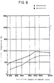
- a partially drawn nylon yarn (P.D.Y.) of 70 De including 24 filaments and a fully drawn yarn (F.D.Y.) of the same size were false twisted by the in-drawing type false twisting machine as illustrated in Figure 5, and the elasticities thereof were measured.
- the results obtained are shown in Table 3 and in Figure 8.
- the undrawn nylon yarns and the partially drawn nylon yarns of 15 De and 35 De have high and stable elasticities of knitted fabrics if the length of the heater is greater than 300 mm, and it is found that false twisted yarns of sufficiently good quality can be obtained even if the heater length is less than 1,000 mm, and particularly less than 800 mm, but greater than 300 mm.
- the elasticity of knitted fabric thereof is insufficient with the heater length ranging from 300 mm to 800 mm.
- Table 3 and Figure 8 showing the test results of the Comparison Example it can be seen that with the nylon yarn of 70 De, the elasticity thereof is low if the heater length is less than 800 mm.
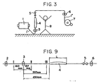
- the temperatures of the yarns were measured at locations I, II and III as illustrated in Figure 9 by means of a temperature detector. The same tests were carried out by varying the feeding speeds of the yarns.
- the undrawn yarn of a higher drawing rate is higher in temperature than the partially drawn yarn of a lower drawing rate.
- the temperature of the feed rollers 3 is substantially equal to room temperature, it is inferred that the nylon yarns are cooled during passage thereof through the feed rollers 3.
- the temperature of a nylon yarns (Free) not twisted after its passage through the feed rollers 3 is compared with that of a nylon yarn (Twist) twisted after its passage through the feed rollers 3, the latter is higher than the former in any of the undrawn yarns, the partially drawn yarns and the fully drawn yarns.
- the partially out-drawn yarn B is lower in temperature than the partially in-drawn yarn C, which is considered due to the fact that with the in-drawing type false twisting machine, the yarn will presumably be drawn within the heater of high temperature disposed downstream of the location II, and hence the partially in-drawn yarn C is free from the influence of self-heating due to drawing thereof.
- the length of a heater in the false twisting process of an undrawn nylon yarn or a partially drawn nylon yarn, the length of a heater can be reduced below 1,000 mm, and particularly below 800 mm if it is greater than 300 mm even when the feeding speed of the yarn is over 500 m/min.
- This provides a remarkable advantage from the viewpoint of minimization in size of a false twisting system.
- the transmission of a twisting movement is reduced if the yarn is bent at a location between the heater and the false twisting means.
Landscapes
- Engineering & Computer Science (AREA)
- Mechanical Engineering (AREA)
- Textile Engineering (AREA)
- Yarns And Mechanical Finishing Of Yarns Or Ropes (AREA)
Claims (7)
Priority Applications (2)
| Application Number | Priority Date | Filing Date | Title |
|---|---|---|---|
| DE8787103605T DE3767300D1 (de) | 1987-03-12 | 1987-03-12 | Falschdrall-kraeuselmaschine. |
| EP19870103605 EP0281657B1 (de) | 1987-03-12 | 1987-03-12 | Falschdrall-Kräuselmaschine |
Applications Claiming Priority (1)
| Application Number | Priority Date | Filing Date | Title |
|---|---|---|---|
| EP19870103605 EP0281657B1 (de) | 1987-03-12 | 1987-03-12 | Falschdrall-Kräuselmaschine |
Publications (2)
| Publication Number | Publication Date |
|---|---|
| EP0281657A1 EP0281657A1 (de) | 1988-09-14 |
| EP0281657B1 true EP0281657B1 (de) | 1991-01-09 |
Family
ID=8196827
Family Applications (1)
| Application Number | Title | Priority Date | Filing Date |
|---|---|---|---|
| EP19870103605 Expired EP0281657B1 (de) | 1987-03-12 | 1987-03-12 | Falschdrall-Kräuselmaschine |
Country Status (2)
| Country | Link |
|---|---|
| EP (1) | EP0281657B1 (de) |
| DE (1) | DE3767300D1 (de) |
Families Citing this family (2)
| Publication number | Priority date | Publication date | Assignee | Title |
|---|---|---|---|---|
| IT1265442B1 (it) * | 1993-12-24 | 1996-11-22 | Menegatto Srl | Macchina testurizzatrice |
| JP4060508B2 (ja) * | 2000-02-16 | 2008-03-12 | Tmtマシナリー株式会社 | 延伸仮撚加工機 |
Family Cites Families (5)
| Publication number | Priority date | Publication date | Assignee | Title |
|---|---|---|---|---|
| US3367096A (en) * | 1965-06-07 | 1968-02-06 | Alamance Ind Inc | Apparatus for false-twisting and plying yarns |
| US3449898A (en) * | 1967-10-10 | 1969-06-17 | Nippon Rayon Kk | Heater for yarn twister |
| US3955351A (en) * | 1969-02-06 | 1976-05-11 | Imperial Chemical Industries Inc. | Production of bulked yarns |
| US3956878A (en) * | 1974-09-10 | 1976-05-18 | Fiber Industries, Inc. | High speed texturing |
| US4173860A (en) * | 1975-03-03 | 1979-11-13 | Mcklveen John R | Textured synthetic fiber yarn and process for making same |
-
1987
- 1987-03-12 DE DE8787103605T patent/DE3767300D1/de not_active Expired - Fee Related
- 1987-03-12 EP EP19870103605 patent/EP0281657B1/de not_active Expired
Also Published As
| Publication number | Publication date |
|---|---|
| DE3767300D1 (de) | 1991-02-14 |
| EP0281657A1 (de) | 1988-09-14 |
Similar Documents
| Publication | Publication Date | Title |
|---|---|---|
| US4226079A (en) | Heather yarn made by combining polyester and polyamide yarns | |
| US4667463A (en) | Process and apparatus for making fasciated yarn | |
| US3945189A (en) | Method of producing knop yarn | |
| US3967441A (en) | Yarns and process for production thereof | |
| US3722202A (en) | Spinning a filament-wrapped staple fiber core yarn | |
| EP0281657A1 (de) | Falschdrall-Kräuselmaschine | |
| US4070817A (en) | Process for texturing synthetic yarns | |
| US3334483A (en) | Method of making direct spinner novelty yarn | |
| US3601972A (en) | Drawing and bulking of synthetic filament yarns | |
| GB2113734A (en) | Spun-fibre yarn produced by interlacing | |
| US3651201A (en) | High-elongation-and-tenacity nylon tire yarn | |
| US3434874A (en) | Acrylic fibers | |
| US3415048A (en) | Process for producing alternating twist | |
| CN101146938A (zh) | 短纤维纱制造方法 | |
| US4528807A (en) | Process for the manufacture of a fancy yarn, and products obtained | |
| US3392521A (en) | Method of making stretch yarn | |
| US3703073A (en) | Antistatic yarn production | |
| US4043108A (en) | Process | |
| GB2142666A (en) | Textile product of the spun fibre yarn type and method and apparatus for its manufacture | |
| Hu et al. | Knitting of basalt filament yarn | |
| US3660973A (en) | Spun yarn and a method for manufacturing the same | |
| EP0034439B1 (de) | Zahnradgekräuselte Effektgarne und Verfahren zu ihrer Herstellung | |
| JPH09157983A (ja) | 複合糸の製造方法 | |
| JPS6262939A (ja) | ナイロン糸の仮撚加工装置 | |
| JP3071922B2 (ja) | 複合加工糸の製造方法 |
Legal Events
| Date | Code | Title | Description |
|---|---|---|---|
| PUAI | Public reference made under article 153(3) epc to a published international application that has entered the european phase |
Free format text: ORIGINAL CODE: 0009012 |
|
| 17P | Request for examination filed |
Effective date: 19880201 |
|
| AK | Designated contracting states |
Kind code of ref document: A1 Designated state(s): CH DE FR GB IT LI |
|
| 17Q | First examination report despatched |
Effective date: 19890126 |
|
| GRAA | (expected) grant |
Free format text: ORIGINAL CODE: 0009210 |
|
| AK | Designated contracting states |
Kind code of ref document: B1 Designated state(s): CH DE FR GB IT LI |
|
| ET | Fr: translation filed | ||
| REF | Corresponds to: |
Ref document number: 3767300 Country of ref document: DE Date of ref document: 19910214 |
|
| ITF | It: translation for a ep patent filed | ||
| PLBE | No opposition filed within time limit |
Free format text: ORIGINAL CODE: 0009261 |
|
| STAA | Information on the status of an ep patent application or granted ep patent |
Free format text: STATUS: NO OPPOSITION FILED WITHIN TIME LIMIT |
|
| 26N | No opposition filed | ||
| PGFP | Annual fee paid to national office [announced via postgrant information from national office to epo] |
Ref country code: GB Payment date: 20010220 Year of fee payment: 15 |
|
| PGFP | Annual fee paid to national office [announced via postgrant information from national office to epo] |
Ref country code: FR Payment date: 20010319 Year of fee payment: 15 |
|
| PGFP | Annual fee paid to national office [announced via postgrant information from national office to epo] |
Ref country code: CH Payment date: 20010323 Year of fee payment: 15 |
|
| PGFP | Annual fee paid to national office [announced via postgrant information from national office to epo] |
Ref country code: DE Payment date: 20010523 Year of fee payment: 15 |
|
| REG | Reference to a national code |
Ref country code: GB Ref legal event code: IF02 |
|
| PG25 | Lapsed in a contracting state [announced via postgrant information from national office to epo] |
Ref country code: GB Free format text: LAPSE BECAUSE OF NON-PAYMENT OF DUE FEES Effective date: 20020312 |
|
| PG25 | Lapsed in a contracting state [announced via postgrant information from national office to epo] |
Ref country code: LI Free format text: LAPSE BECAUSE OF NON-PAYMENT OF DUE FEES Effective date: 20020331 Ref country code: CH Free format text: LAPSE BECAUSE OF NON-PAYMENT OF DUE FEES Effective date: 20020331 |
|
| PG25 | Lapsed in a contracting state [announced via postgrant information from national office to epo] |
Ref country code: DE Free format text: LAPSE BECAUSE OF NON-PAYMENT OF DUE FEES Effective date: 20021001 |
|
| GBPC | Gb: european patent ceased through non-payment of renewal fee |
Effective date: 20020312 |
|
| REG | Reference to a national code |
Ref country code: CH Ref legal event code: PL |
|
| PG25 | Lapsed in a contracting state [announced via postgrant information from national office to epo] |
Ref country code: FR Free format text: LAPSE BECAUSE OF NON-PAYMENT OF DUE FEES Effective date: 20021129 |
|
| REG | Reference to a national code |
Ref country code: FR Ref legal event code: ST |
|
| PG25 | Lapsed in a contracting state [announced via postgrant information from national office to epo] |
Ref country code: IT Free format text: LAPSE BECAUSE OF NON-PAYMENT OF DUE FEES Effective date: 20050312 |