EP0281782B1 - Cage de laminoir - Google Patents
Cage de laminoir Download PDFInfo
- Publication number
- EP0281782B1 EP0281782B1 EP88101992A EP88101992A EP0281782B1 EP 0281782 B1 EP0281782 B1 EP 0281782B1 EP 88101992 A EP88101992 A EP 88101992A EP 88101992 A EP88101992 A EP 88101992A EP 0281782 B1 EP0281782 B1 EP 0281782B1
- Authority
- EP
- European Patent Office
- Prior art keywords
- rolls
- stand
- roll
- chocks
- working
- Prior art date
- Legal status (The legal status is an assumption and is not a legal conclusion. Google has not performed a legal analysis and makes no representation as to the accuracy of the status listed.)
- Expired - Lifetime
Links
- 238000005096 rolling process Methods 0.000 title abstract description 24
- 238000000034 method Methods 0.000 claims description 9
- 238000009434 installation Methods 0.000 claims description 7
- 238000006073 displacement reaction Methods 0.000 claims description 4
- 238000004519 manufacturing process Methods 0.000 claims description 4
- 125000006850 spacer group Chemical group 0.000 abstract description 17
- 238000013000 roll bending Methods 0.000 description 4
- 230000006978 adaptation Effects 0.000 description 3
- 230000009977 dual effect Effects 0.000 description 3
- 238000005452 bending Methods 0.000 description 2
- 238000006243 chemical reaction Methods 0.000 description 1
- 238000009420 retrofitting Methods 0.000 description 1
- 229910001220 stainless steel Inorganic materials 0.000 description 1
- 239000010935 stainless steel Substances 0.000 description 1
Images


Classifications
-
- B—PERFORMING OPERATIONS; TRANSPORTING
- B21—MECHANICAL METAL-WORKING WITHOUT ESSENTIALLY REMOVING MATERIAL; PUNCHING METAL
- B21B—ROLLING OF METAL
- B21B13/00—Metal-rolling stands, i.e. an assembly composed of a stand frame, rolls, and accessories
- B21B13/001—Convertible or tiltable stands, e.g. from duo to universal stands, from horizontal to vertical stands
-
- B—PERFORMING OPERATIONS; TRANSPORTING
- B21—MECHANICAL METAL-WORKING WITHOUT ESSENTIALLY REMOVING MATERIAL; PUNCHING METAL
- B21B—ROLLING OF METAL
- B21B13/00—Metal-rolling stands, i.e. an assembly composed of a stand frame, rolls, and accessories
- B21B13/02—Metal-rolling stands, i.e. an assembly composed of a stand frame, rolls, and accessories with axes of rolls arranged horizontally
- B21B2013/026—Quinto, five high-stands
-
- B—PERFORMING OPERATIONS; TRANSPORTING
- B21—MECHANICAL METAL-WORKING WITHOUT ESSENTIALLY REMOVING MATERIAL; PUNCHING METAL
- B21B—ROLLING OF METAL
- B21B13/00—Metal-rolling stands, i.e. an assembly composed of a stand frame, rolls, and accessories
- B21B13/02—Metal-rolling stands, i.e. an assembly composed of a stand frame, rolls, and accessories with axes of rolls arranged horizontally
- B21B2013/028—Sixto, six-high stands
-
- B—PERFORMING OPERATIONS; TRANSPORTING
- B21—MECHANICAL METAL-WORKING WITHOUT ESSENTIALLY REMOVING MATERIAL; PUNCHING METAL
- B21B—ROLLING OF METAL
- B21B31/00—Rolling stand structures; Mounting, adjusting, or interchanging rolls, roll mountings, or stand frames
- B21B31/08—Interchanging rolls, roll mountings, or stand frames, e.g. using C-hooks; Replacing roll chocks on roll shafts
- B21B31/10—Interchanging rolls, roll mountings, or stand frames, e.g. using C-hooks; Replacing roll chocks on roll shafts by horizontally displacing, i.e. horizontal roll changing
-
- B—PERFORMING OPERATIONS; TRANSPORTING
- B21—MECHANICAL METAL-WORKING WITHOUT ESSENTIALLY REMOVING MATERIAL; PUNCHING METAL
- B21B—ROLLING OF METAL
- B21B31/00—Rolling stand structures; Mounting, adjusting, or interchanging rolls, roll mountings, or stand frames
- B21B31/16—Adjusting or positioning rolls
- B21B31/20—Adjusting or positioning rolls by moving rolls perpendicularly to roll axis
- B21B31/22—Adjusting or positioning rolls by moving rolls perpendicularly to roll axis mechanically, e.g. by thrust blocks, inserts for removal
- B21B31/30—Adjusting or positioning rolls by moving rolls perpendicularly to roll axis mechanically, e.g. by thrust blocks, inserts for removal by wedges or their equivalent
Definitions
- the present invention relates to a method for converting a rolling stand from one stand variant to another stand variant with a variable number of effective rollers, for producing a rolling stock, in particular a rolled strip, the rollers to be used in accordance with the intended stand variant being used as exchange units.
- a method according to the preamble of claim 1 is already known from JP-A-61-180601.
- a rolling stand for producing a rolling stock, in particular a rolled strip, is described in EP-PS 0059417.
- the known device is provided with a roller bending device, the chocks of the intermediate rollers being guided between blocks anchored in the stator windows and connected to the blocks by piston-cylinder units which can be acted upon on both sides and which are assigned to the blocks, and to which one block is attached to each block Guide piece is guided vertically displaceable and the guide pieces are positively connected to the chocks by horizontal guides in the vertical direction.
- JP-A-61-180601 describes a roll stand in which, for the purpose of an improved and quick changeover from a four-high to a six-high stand and vice versa, slim work rolls with horizontal intermediate rolls or support rolls are designed as a changing unit in cassette form. An arrangement of the work or intermediate rolls to be replaced in a vertical plane within an exchange unit is not provided in the known horizontal arrangement. This roll stand cannot be converted to a duo stand either.
- the invention has for its object to provide a method for converting a rolling stand from one stand variant to another stand variant with a variable number of effective rollers, for producing a rolling stock, in particular a rolled strip, with which the disadvantages mentioned are avoided and the difficulties are eliminated.
- the retrofitting should be possible in a simple manner for different usage variants in order to be able to convert a roll stand quickly and with a minimum of technical effort from one stand to another stand with a changed number of effective rolls.
- a trouble-free production process with still reasonable changeover times should be guaranteed without loss of quality for the rolled product.
- the object is achieved according to the invention in a method of the type mentioned above in that the rollers to be used are used together with their chocks in a vertical arrangement between the support rollers by means of positive locking and with the possibility of displacement along the roller axis in guides fastened to the roller stand, with the For the purpose of using the stand as a duo stand, spacers are inserted between the chocks of the work rolls and the chocks of the backup rolls.
- a rolling stand can advantageously be converted to a six-high reduction stand as well as a duo stand or a four-high stand with comparatively short changeover times.
- the intermediate roll bending block can advantageously be used as a new work roll bending block.
- the intermediate rolls and the work rolls with their bearings are arranged in a vertical plane in a cassette which, as a vertical quick-change unit, can be exchanged for another cassette with duo rolls.
- Holding and guiding devices can advantageously be dispensed with, which saves production costs and downtimes and the support rollers remain in the stand.
- a rolling mill operated as a six-high reduction stand or reversing stand e.g. B. for the production of stainless steel strip with an initial thickness of about 8 mm to a final thickness of about 0.4 mm, can be used in a simple manner as a double skin pass mill in the same roll stand. All that is required is to replace the intermediate and work rolls of the six-roll arrangement with a duo arrangement, an air gap remaining as a result of the spacers inserted between the support rolls and the new work rolls.
- the air gap between work and backup rolls can be brought to zero, so that after removal of the spacers, the transfer of the rolling forces takes place directly between support rolls and work rolls, and not as with the duo scaffold over the chocks of the backup rolls on the chocks of the work rolls.
- the work rolls can be exchanged briefly individually or together, with the backup rolls remaining in the stand.
- plates are used as spacers and releasably connected to the chocks of the work rolls. This is a particularly simple and inexpensive measure to form an air gap between the work and backup rolls in the dual skin pass mill.
- the measure can advantageously be used in such a way that several plates are placed one above the other to form a spacer.
- the total thickness of the spacers is adapted to the expected or approved roll wear, so that an air gap between the work and backup rolls is constantly maintained during operation of the roll stand as a duo rolling mill.
- the spacers can advantageously be assembled with the chocks to form an element connection by means of a positive connection. This is a measure that ensures a particularly quick change or installation of the spacers.
- the work rolls can have a bale contour that is curved differently in the direction of the two ends, in particular asymmetrical.
- a Optimal influence on the roll gap in adaptation to the surface conditions of the rolling stock on the one hand and on the other to the roll wear.
- the support rolls can have a bend contour that is curved differently in the direction of the two ends, in particular asymmetrical, whereby the roll gap is also influenced.
- a particularly precise adaptation of the roll gap to the changing rolling conditions can be carried out.
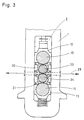
- the six-high mill stand shown has in the usual way two roller stands (1) arranged at a distance from one another, only one of which is shown in detail.
- the roll stands (1) each have a stand window (2), in which two slim work rolls (3, 4) are received, which are supported on both sides by the support arms (5, 6; 7, 8) in a known manner.
- the support rollers (10, 11) also located in the frame (1) or in the stand window (2) are, as is known, mounted in chocks (12, 13) at their ends. Between the slender work rolls (3, 4) and the support rolls (10, 11) there are intermediate rolls (14, 15) which in turn are held by their chocks (16, 17).
- the intermediate rollers (14, 15) there are stator-fixed blocks with guide pieces (20, 21; 22, 23) in the stator windows (2) of the two roller stands (1), which are guided vertically displaceably in the stator-fixed blocks, whereby the insert pieces (16, 17) for the two intermediate rolls (14, 15) are positively connected in the vertical direction, but are horizontally displaceable with the guide pieces (20-23) for the changing process.
- the chocks (16, 17) of the upper and lower intermediate rollers (14, 15) are each assigned adjusting means (24 - 27) in the form of hydraulically actuated piston-cylinder units in the area of the blocks fixed to the stand.
- These adjustment means or bending devices (24-27) for the intermediate rollers (14, 15) are each installed in the associated guide pieces (20-23).
- the chocks (12) of the upper support roller (10) are attacked by the adjusting device (28) of the roll stand.
- the rolling forces are first transferred in a known manner via the chocks (12, 13) onto the support rolls (10, 11), then at the points of contact of the support rolls (10, 11) with the intermediate rolls (14, 15 ) to this and from there to the work rolls (3, 4) or the rolling stock rolled in the rolling plane (29).
- FIG. 2 shows the use of the roll stand as a dual skin pass stand
- the chocks (30, 31) of the new thick work rolls (33, 34) with spacers (35, 36) compared to the chocks (12, 13) of the support rolls (10, 11 ) are provided so that there is no contact between the bales of the support rollers (10, 11) and the bales of the thick work rollers (33, 34).
- the chocks (30, 31) of the work rolls (33, 34) fit into the guide pieces (20 - 23), which serve as guides for the chocks of the intermediate rolls when used as a sex scaffold according to FIG. 1 (see FIG. 1, Chocks 16, 17; intermediate rolls 14, 15).
- the intermediate roll bending block with the adjusting means (24-27) can advantageously be used as a new work roll bending block for crowning the work rolls (33, 34).
- the spacers (35, 36) are designed as plates and are detachably connected to the chocks (30, 31) of the work rolls (33, 34), a plurality of plates one above the other forming a spacer (35, 36) can form.
- the intermediate rolls with their bearings and the slim work rolls are moved out of the stand windows (2) as a quick-change unit, with the support arms (5 - 8) are retracted hydraulically as far as possible to create space for the thick work rolls (33, 34) and their chocks (30, 31).
- the chocks (12, 13) with the support rollers (10, 11) are moved apart via the adjusting means (24 - 27) and the new work rollers (33, 34) together with the chocks (30, 31) and the spacers connected to them ( 35, 36) moved into the stand window (2).
- the adjustment means (24 - 27) are now released.
- the rolling forces are transmitted via the chocks (12, 13), the spacers (35, 36), the chocks (30, 31) to the thick work rolls (33, 34).
- the dual skin pass mill when the spacers are removed (cf. FIG. 2, numbers 35, 36), the dual skin pass mill can also be used as a four-high stand, in particular when transmitting rolling forces of more than 2000 t.
- the rolling forces are then introduced directly between support rolls (10, 11) and work rolls (33, 34), i. H. without detour via the chocks (12, 13) and (30, 31).
- the spacers can have any shape and can be divided not only horizontally but also vertically.
- the respective structural design is left to the person skilled in the art in adaptation to the use.
Landscapes
- Engineering & Computer Science (AREA)
- Mechanical Engineering (AREA)
- Metal Rolling (AREA)
- Reduction Rolling/Reduction Stand/Operation Of Reduction Machine (AREA)
- Bending Of Plates, Rods, And Pipes (AREA)
- Coating With Molten Metal (AREA)
- Rolls And Other Rotary Bodies (AREA)
- Crushing And Grinding (AREA)
Claims (4)
- Procédé de transformation d'une cage de laminoir permettant de passer d'une variante de cage à une autre variante de cage comportant un nombre différent de cylindres actifs pour la fabrication d'un produit laminé, notamment d'une bande laminée, les cylindres qui doivent être mis en place compte tenu de la variante de cage prévue étant mis en place comme des unitée de changement, caractérisé en ce que les cylindres (3, 4, 14, 15, 33, 34) qui doivent être mis en place le sont, avec leurs empoises (16, 17, 30, 37) dans une disposition verticale entre les cylindres d'appui (10, 11) avec adaptation des formes et avec possibilité de déplacement le long de l'axe du cylindre dans des dispositifs de guidage (20 à 23) fixés dans la cage de laminoir et en ce que, pour permettre l'utilisation de la cage comme cage duo, des pièces de maintien à distance (35, 36) sont intercalées entre des empoises (30, 31) des cylindres de travail (33, 34) et les empoises (12, 13) des cylindres d'appui (10, 11).
- Procédé selon la revendication 1, caractérisé en ce que les pièces de maintien à distance (35, 36) sont constituées par des plaques reliées d'une manière amovible aux empoises (30, 31) des cylindres de travail (33, 34).
- Procédé selon l'une des revendications 1 ou 2, caractérisé en ce que plusieurs plaques sont superposées pour réaliser une pièce de maintien à distance (35, 36).
- Procédé selon l'une des revendications 1, 2 ou 3, caractérisé en ce que les pièces de maintien à distance (35, 36) sont associées aux empoises (30, 31) avec adaptation des formes pour réaliser une liaison d'éléments.
Priority Applications (1)
| Application Number | Priority Date | Filing Date | Title |
|---|---|---|---|
| AT88101992T ATE72147T1 (de) | 1987-03-10 | 1988-02-11 | Walzgeruest. |
Applications Claiming Priority (2)
| Application Number | Priority Date | Filing Date | Title |
|---|---|---|---|
| DE19873707560 DE3707560A1 (de) | 1987-03-10 | 1987-03-10 | Walzgeruest |
| DE3707560 | 1987-03-10 |
Publications (2)
| Publication Number | Publication Date |
|---|---|
| EP0281782A1 EP0281782A1 (fr) | 1988-09-14 |
| EP0281782B1 true EP0281782B1 (fr) | 1992-01-29 |
Family
ID=6322631
Family Applications (1)
| Application Number | Title | Priority Date | Filing Date |
|---|---|---|---|
| EP88101992A Expired - Lifetime EP0281782B1 (fr) | 1987-03-10 | 1988-02-11 | Cage de laminoir |
Country Status (5)
| Country | Link |
|---|---|
| US (1) | US4841761A (fr) |
| EP (1) | EP0281782B1 (fr) |
| JP (1) | JP2509659B2 (fr) |
| AT (1) | ATE72147T1 (fr) |
| DE (2) | DE3707560A1 (fr) |
Families Citing this family (13)
| Publication number | Priority date | Publication date | Assignee | Title |
|---|---|---|---|---|
| FR2648372A1 (fr) * | 1989-06-19 | 1990-12-21 | Clecim Sa | Procede de changement de configuration d'un laminoir et installation de laminage pour la mise en oeuvre du procede |
| DE3930125C2 (de) * | 1989-09-09 | 1997-02-20 | Schloemann Siemag Ag | Umrüstbares Walzgerüst |
| US5622073A (en) * | 1991-05-16 | 1997-04-22 | Kawasaki Steel Corporation | Six high rolling mill |
| DE4337935A1 (de) * | 1993-11-06 | 1995-05-11 | Schloemann Siemag Ag | Horizontal-Vertikal-Walzgerüst |
| DE4340313A1 (de) * | 1993-11-26 | 1995-06-01 | Schloemann Siemag Ag | Walzgerüst |
| DE4417274C2 (de) * | 1994-05-18 | 2003-04-17 | Sms Demag Ag | Verfahren zum Betreiben eines Walzgerüstes |
| DE10150146A1 (de) * | 2001-10-11 | 2003-04-17 | Sms Demag Ag | Walzgutführungseinrichtung an Vertikalwalzgerüsten |
| FR2846579B1 (fr) * | 2002-11-05 | 2006-05-05 | Vai Clecim | Procede pour elargir la gamme de production d'une installation de laminage de produits metalliques et installation pour la mise en oeuvre du procede |
| FR2851942B1 (fr) * | 2003-03-05 | 2006-04-28 | Procede de changement de configuration d'un laminoir et laminoir perfectionne pour la mise en oeuvre du procede | |
| US20040177462A1 (en) | 2003-03-14 | 2004-09-16 | The Gillette Company | Toothbrush head |
| US7941886B2 (en) | 2003-09-19 | 2011-05-17 | Braun Gmbh | Toothbrushes |
| CN102886380B (zh) * | 2011-07-20 | 2014-12-03 | 宝山钢铁股份有限公司 | 适合于软质钢的负弯辊平整轧制方法 |
| AT522073B1 (de) * | 2019-05-16 | 2020-08-15 | Primetals Technologies Austria GmbH | Warmwalzen mit flexibler Konfiguration der Walzgerüste |
Family Cites Families (7)
| Publication number | Priority date | Publication date | Assignee | Title |
|---|---|---|---|---|
| US2039959A (en) * | 1933-12-28 | 1936-05-05 | Mesta Machine Co | Rolling mill |
| NL283877A (fr) * | 1961-12-21 | |||
| US4519233A (en) * | 1980-10-15 | 1985-05-28 | Sms Schloemann-Siemag Ag | Roll stand with noncylindrical rolls |
| DE3038865C1 (de) * | 1980-10-15 | 1982-12-23 | SMS Schloemann-Siemag AG, 4000 Düsseldorf | Walzgeruest mit axial verschiebbaren Walzen |
| DE3261730D1 (en) * | 1981-02-28 | 1985-02-14 | Schloemann Siemag Ag | Roll stand |
| US4531394A (en) * | 1982-03-26 | 1985-07-30 | T. Sendzimir, Inc. | Six-high rolling mills |
| EP0235332B1 (fr) * | 1986-03-04 | 1990-10-03 | MANNESMANN Aktiengesellschaft | Cage de laminoir |
-
1987
- 1987-03-10 DE DE19873707560 patent/DE3707560A1/de not_active Withdrawn
-
1988
- 1988-02-11 AT AT88101992T patent/ATE72147T1/de not_active IP Right Cessation
- 1988-02-11 EP EP88101992A patent/EP0281782B1/fr not_active Expired - Lifetime
- 1988-02-11 DE DE8888101992T patent/DE3868087D1/de not_active Expired - Lifetime
- 1988-03-09 US US07/165,699 patent/US4841761A/en not_active Expired - Lifetime
- 1988-03-10 JP JP63055078A patent/JP2509659B2/ja not_active Expired - Fee Related
Also Published As
| Publication number | Publication date |
|---|---|
| JP2509659B2 (ja) | 1996-06-26 |
| DE3707560A1 (de) | 1988-09-22 |
| US4841761A (en) | 1989-06-27 |
| EP0281782A1 (fr) | 1988-09-14 |
| DE3868087D1 (de) | 1992-03-12 |
| ATE72147T1 (de) | 1992-02-15 |
| JPS63235008A (ja) | 1988-09-30 |
Similar Documents
| Publication | Publication Date | Title |
|---|---|---|
| DE602004007631T2 (de) | Verfahren zum ändern der konfiguration eines walzgerüstes sowie ein zur durchführung des verfahrens geeignetes walzgerüst | |
| EP0235332B1 (fr) | Cage de laminoir | |
| EP0049798B1 (fr) | Laminoir | |
| EP0281782B1 (fr) | Cage de laminoir | |
| EP0256409B1 (fr) | Procédé de fabrication de profils | |
| DE2206912A1 (de) | Walzgerüst | |
| DE10210576B4 (de) | Walzanlage für Flachgut und Tandem-Walzanlage mit mindestens einem Doppel-Walzgerüst und Verfahren zum Entfernen eines in solch einem Doppel-Walzgerüst befindlichen Walzgutabschnitts | |
| DE10150690A1 (de) | Walzvorrichtung | |
| DE19807785C1 (de) | Biegevorrichtung für Vier- oder Mehrwalzengerüste | |
| EP0143166B1 (fr) | Cage de laminoir avec appui des cylindres de travail à l'aide de rouleaux d'appui | |
| EP0857522B1 (fr) | Train de laminage | |
| DE102010049908B4 (de) | Vielwalzen-Walzwerk vom Cluster-Typ | |
| DE29980239U1 (de) | Walzwerk mit zweidimensional gesteuerter Walzendurchbiegung | |
| DE29780451U1 (de) | Hochgenaues Walzwerk mit zweidimensionaler Biegungssteuerung | |
| EP0560115A1 (fr) | Procédé et laminoir pour le laminage de précision de fil respectivement de produit laminé à section circulaire | |
| DE3844162C2 (fr) | ||
| DE69103116T2 (de) | Vorrichtung zum Anstellen der Walzkaliber in einem Walzgerüst. | |
| EP0870554B1 (fr) | Train de laminoirs pour laminer des aciers plats | |
| AT393804B (de) | Walzwerk, insbesondere rohrkontiwalzwerk | |
| DE2844438A1 (de) | Walzstrasse zum walzen von schweren traegerprofilen oder schienen | |
| DE10257971A1 (de) | Mehrwalzengerüst zum Walzen eines Metallbandes | |
| AT390741B (de) | Walzwerk, insbesondere kaltwalzwerk | |
| EP4504434B1 (fr) | Dispositif de guidage pour cales de cylindres de travail dans une cage de laminage | |
| DE69402916T2 (de) | System zum Walzen von mindestens zwei Profilen in Blöcken von Hochgeschwindigkeitswalzgerüsten | |
| EP4377024B1 (fr) | Procédé et installation de laminage à chaud de produits à laminer métalliques |
Legal Events
| Date | Code | Title | Description |
|---|---|---|---|
| PUAI | Public reference made under article 153(3) epc to a published international application that has entered the european phase |
Free format text: ORIGINAL CODE: 0009012 |
|
| 17P | Request for examination filed |
Effective date: 19880222 |
|
| AK | Designated contracting states |
Kind code of ref document: A1 Designated state(s): AT BE DE FR GB IT |
|
| 17Q | First examination report despatched |
Effective date: 19891205 |
|
| GRAA | (expected) grant |
Free format text: ORIGINAL CODE: 0009210 |
|
| AK | Designated contracting states |
Kind code of ref document: B1 Designated state(s): AT BE DE FR GB IT |
|
| REF | Corresponds to: |
Ref document number: 72147 Country of ref document: AT Date of ref document: 19920215 Kind code of ref document: T |
|
| PGFP | Annual fee paid to national office [announced via postgrant information from national office to epo] |
Ref country code: AT Payment date: 19920213 Year of fee payment: 5 |
|
| PGFP | Annual fee paid to national office [announced via postgrant information from national office to epo] |
Ref country code: FR Payment date: 19920214 Year of fee payment: 5 |
|
| REF | Corresponds to: |
Ref document number: 3868087 Country of ref document: DE Date of ref document: 19920312 |
|
| PGFP | Annual fee paid to national office [announced via postgrant information from national office to epo] |
Ref country code: GB Payment date: 19920320 Year of fee payment: 5 Ref country code: BE Payment date: 19920320 Year of fee payment: 5 |
|
| ITF | It: translation for a ep patent filed | ||
| ET | Fr: translation filed | ||
| GBT | Gb: translation of ep patent filed (gb section 77(6)(a)/1977) | ||
| PLBE | No opposition filed within time limit |
Free format text: ORIGINAL CODE: 0009261 |
|
| STAA | Information on the status of an ep patent application or granted ep patent |
Free format text: STATUS: NO OPPOSITION FILED WITHIN TIME LIMIT |
|
| 26N | No opposition filed | ||
| PG25 | Lapsed in a contracting state [announced via postgrant information from national office to epo] |
Ref country code: GB Effective date: 19930211 Ref country code: AT Effective date: 19930211 |
|
| PG25 | Lapsed in a contracting state [announced via postgrant information from national office to epo] |
Ref country code: BE Effective date: 19930228 |
|
| BERE | Be: lapsed |
Owner name: SCHLOEMANN-SIEMAG A.G. SMS Effective date: 19930228 |
|
| GBPC | Gb: european patent ceased through non-payment of renewal fee |
Effective date: 19930211 |
|
| PG25 | Lapsed in a contracting state [announced via postgrant information from national office to epo] |
Ref country code: FR Effective date: 19931029 |
|
| REG | Reference to a national code |
Ref country code: FR Ref legal event code: ST |
|
| PGFP | Annual fee paid to national office [announced via postgrant information from national office to epo] |
Ref country code: DE Payment date: 20030208 Year of fee payment: 16 |
|
| PG25 | Lapsed in a contracting state [announced via postgrant information from national office to epo] |
Ref country code: DE Free format text: LAPSE BECAUSE OF NON-PAYMENT OF DUE FEES Effective date: 20040901 |
|
| PG25 | Lapsed in a contracting state [announced via postgrant information from national office to epo] |
Ref country code: IT Free format text: LAPSE BECAUSE OF NON-PAYMENT OF DUE FEES;WARNING: LAPSES OF ITALIAN PATENTS WITH EFFECTIVE DATE BEFORE 2007 MAY HAVE OCCURRED AT ANY TIME BEFORE 2007. THE CORRECT EFFECTIVE DATE MAY BE DIFFERENT FROM THE ONE RECORDED. Effective date: 20050211 |