EP0281827A2 - Kesselwagen zum Transport gefährlicher Güter - Google Patents
Kesselwagen zum Transport gefährlicher Güter Download PDFInfo
- Publication number
- EP0281827A2 EP0281827A2 EP88102509A EP88102509A EP0281827A2 EP 0281827 A2 EP0281827 A2 EP 0281827A2 EP 88102509 A EP88102509 A EP 88102509A EP 88102509 A EP88102509 A EP 88102509A EP 0281827 A2 EP0281827 A2 EP 0281827A2
- Authority
- EP
- European Patent Office
- Prior art keywords
- boiler
- saddle
- tank wagon
- height
- side plates
- Prior art date
- Legal status (The legal status is an assumption and is not a legal conclusion. Google has not performed a legal analysis and makes no representation as to the accuracy of the status listed.)
- Granted
Links
Images

Classifications
-
- B—PERFORMING OPERATIONS; TRANSPORTING
- B61—RAILWAYS
- B61D—BODY DETAILS OR KINDS OF RAILWAY VEHICLES
- B61D5/00—Tank wagons for carrying fluent materials
- B61D5/06—Mounting of tanks; Integral bodies and frames
Definitions
- the invention relates to a tank wagon for the transport of dangerous goods, in particular for the transport of toxic and groundwater-endangering substances, consisting of a boiler with a arranged on the top of the boiler, the connection fittings containing dome and a connected via saddle side plates and saddle rails with the boiler, supporting the buffer frame.
- the dome with the connection fittings is placed on the top of the boiler, so that it can tear off when the wagon is derailed and the load can run out.
- connection fittings sunk in the bottom of the boiler, damage to the fittings and leakage of the cargo can also occur here in rear-end collisions.
- DE-AS 16 05 105 shows a tank car in which the boiler is connected to the base frame by means of support strips and side plates.
- DE-PS 11 79 980 also shows a tank car in which the boiler is mounted on the base frame via side plates. The side plates are always attached to the boiler in the lower area of the boiler, so that when the wagons are derailed, neither the flanks nor the headers of the boiler are protected.
- a tank car for the transport of dangerous goods, in particular the transport of toxic and groundwater-endangering substances, consisting of a boiler with a dome arranged on the top of the boiler, containing the connection fittings, and a saddle side plate and Saddle support strips connected to the boiler, supporting the buffer frame, which is built to be as accident-proof as possible and offers the greatest possible protection against the leakage of goods in all conceivable transport accidents.
- the dome is arranged with the connection fittings within the contour of the boiler, and that the saddle side plates extend over the entire length of the base frame, are fastened to the saddle support strips without significantly projecting laterally from the diameter of the boiler, and have a height above the base frame of at least the diameter of a buffer plate.
- the front and rear narrow sides of the saddle side plates are each provided with vertical metal plates attached vertically to it as ramming planks, the height and width of which in each case correspond to at least the diameter of a buffer plate.
- the height of the saddle side plates above the base frame outside the boiler area and the height and width of the ramming planks preferably each correspond to 1.1 to 1.5 times the diameter of the buffer plates.
- the saddle support strips are attached to the boiler at approximately half the boiler height and are designed as a hollow box profile, in particular as a trapezoidal hollow box profile, the long side of which faces the boiler wall.
- the material thickness of the saddle support bar should be less than that of the boiler, so that in the event of accidents with impact loads, the bar profile is first deformed and absorbs the corresponding deformation energy. It is therefore also advantageous to surround the boiler in a ring shape with hollow box profiles as reinforcing ribs.
- the ramming planks As additional protection in the event of rear-end collisions, it has proven to be advantageous to provide the ramming planks with a nose facing the buffers at the upper end.
- the distance between the ramming planks and the boiler is preferably approximately 1.5 times the distance between the buffer plate and the buffer attachment on the base frame.
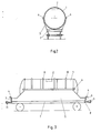
- FIGS I to III schematically show a longitudinal and a cross section through an exemplary embodiment of the tank car according to the invention and a side view.
- the tank car consists of a horizontally mounted boiler (1) on a base frame (7), which is provided with four buffers (11).
- the dome (2) is integrated so that it lies within the contour of the boiler (1).
- Horizontal saddle support strips (6), to which the saddle side plates (5) are attached, are attached to the longitudinal sides of the boiler (1) at about half the height of the boiler. Although these can protrude upwards from the saddle support rails (6), they must not increase the clear side profile of the tank wagon.
- the saddle side plates (5) extend over the entire length of the base frame (7), the height above the base frame (7) outside the boiler area corresponding at least to the diameter of the buffer plate (9). As a result, they act as side protection.
- ramming planks (3) perpendicular to the narrow sides, the height and width of which correspond at least to the diameter of the buffer plate (9).
- the ramming planks (3) preferably carry a nose (4) in order to prevent the buffers (11) of another coupled wagon from climbing onto the underframe and possibly damaging the boiler (1), which can also be reinforced with hollow box-shaped reinforcing ribs (10 ) can surround.
- tank wagons are particularly suitable for the transport of acrolein, hydrocyanic acid or mercaptans.
Landscapes
- Engineering & Computer Science (AREA)
- Transportation (AREA)
- Mechanical Engineering (AREA)
- Handcart (AREA)
- Air Transport Of Granular Materials (AREA)
- Packages (AREA)
- Processing Of Solid Wastes (AREA)
- Details Of Rigid Or Semi-Rigid Containers (AREA)
- Cooling, Air Intake And Gas Exhaust, And Fuel Tank Arrangements In Propulsion Units (AREA)
Abstract
Description
- Die Erfindung betrifft einen Kesselwagen zum Transport gefährlicher Güter, insbesondere zum Transport giftiger und grundwassergefährdender Stoffe, bestehend aus einem Kessel mit einem am Kesselscheitel angeordneten, die Anschlußarmaturen enthaltenden Dom und einem über Sattelseitenbleche und Satteltragleisten mit dem Kessel verbundenen, die Puffer tragenden Untergestell.
- Bei den bekannten Kesselwagen ist der Dom mit den Anschlußarmaturen auf dem Kesselscheitel aufgesetzt, so daß dieser bei einem Entgleisen des Wagens abreißen und das Ladegut auslaufen kann. Zwar ist es auch bekannt, die Anschlußarmaturen versenkt im Kesselboden anzuordnen, doch kann auch hier bei Auffahrunfällen eine Beschädigung der Armaturen und ein Auslaufen des Ladeguts erfolgen.
- In der DE-AS 16 05 105 wird ein Kesselwagen gezeigt, bei dem der Kessel über Tragleisten und Seitenbleche mit dem Untergestell verbunden ist. Auch die DE-PS 11 79 980 zeigt einen Kesselwagen, bei dem der Kessel über Seitenbleche auf dem Untergestell montiert ist. Die Befestigung der Seitenbleche am Kessel erfolgt hierbei stets im unteren Kesselbereich, so daß bei einem Entgleisen der Wagen weder ein Schutz der Flanken noch der Kopfstücke des Kessels gegeben ist.
- Es war daher Aufgabe der vorliegenden Erfindung, einen Kesselwagen zum Transport gefährlicher Güter, insbesondere Transport giftiger und grundwassergefährdender Stoffe zu konstruieren, bestehend aus einem Kessel mit einem am Kesselscheitel angeordneten, die Anschlußarmaturen enthaltenden Dom und einem über Sattelseitenbleche und Satteltragleisten mit dem Kessel verbundenen, die Puffer tragenden Untergestell, der möglichst unfallsicher gebaut und bei allen denkbaren Transportunfällen einen größtmöglichen Schutz vor dem Auslaufen der Güter bietet.
- Diese Aufgabe wird erfindungsgemäß dadurch gelöst, daß der Dom mit den Anschlußarmaturen innerhalb der Kontur des Kessels angeordnet ist,
und daß die Sattelseitenbleche sich über die gesamte Länge des Untergestells erstrecken, an den Satteltragleisten befestigt sind, ohne den Durchmesser des Kessels seitlich wesentlich zu überragen, und außerhalb des Kesselbereichs eine Höhe über dem Untergestell von mindestens dem Durchmesser eines Puffertellers besitzen.
Vorteilhafterweise sind die vorderen und hinteren Schmalseiten der Sattelseitenbleche jeweils mit senkrecht dazu befestigten, vertikalen Metallplatten als Rammbohlen versehen, deren Höhe und Breite jeweils zumindest dem Durchmesser eines Puffertellers entsprechen. - Vorzugsweise entspricht die Höhe der Sattelseitenbleche über dem Untergestell außerhalb des Kesselbereichs und die Höhe und Breite der Rammbohlen jeweils dem 1,1 bis 1,5-fachen des Durchmessers der Pufferteller.
- Weiterhin ist es vorteilhaft, wenn die Satteltragleisten in etwa halber Kesselhöhe am Kessel befestigt und als Hohlkastenprofil ausgebildet sind, insbesondere als trapezförmiges Hohlkastenprofil, dessen lange Seite der Kesselwand zugekehrt ist.
- Dabei sollte die Materialstärke der Satteltragleiste geringer sein als die des Kessels, damit bei Unfällen mit Stoßbelastung zunächst das Leistenprofil verformt wird und entsprechende Verformungsenergien aufnimmt. Daher ist es auch von Vorteil, den Kessel ringförmig mit Hohlkastenpröfilen als Verstärkungsrippen zu umgeben.
- Als zusätzlicher Schutz bei Auffahrunfällen hat es sich als vorteilhaft erwiesen, die Rammbohlen am oberen Ende mit jeweils einer den Puffern zugewandten Nase zu versehen. Vorzugsweise beträgt der Abstand der Rammbohlen vom Kessel etwa das 1,5-fache des Abstands des Puffertellers von der Pufferbefestigung am Untergestell.
- Die Abbildungen I bis III zeigen schematisch einen Längs- und einen Querschnitt durch eine beispielhafte Ausführungsform des erfindungsgemäßen Kesselwagens und eine Seitenansicht.
Der Kesselwagen besteht aus einem horizontal gelagerten Kessel (1) auf einem Untergestell (7), das mit vier Puffern (11) versehen ist. In dem Kessel (1) ist der Dom (2) so integriert, daß er innerhalb der Kontur des Kessels (1) liegt. In etwa halber Kesselhöhe sind auf den Längsseiten des Kessels (1) horizontale Satteltragleisten (6) angebracht, an denen die Sattelseitenbleche (5) befestigt sind. Diese können zwar die Satteltragleisten (6) nach oben überragen, dürfen aber das lichte Seitenprofil des Kesselwagens nicht vergrößern. Die Sattelseitenbleche (5) erstrecken sich über die gesamte Länge des Untergestells (7), wobei die Höhe über dem Untergestell (7) außerhalb des Kesselbereichs mindestens dem Durchmesser der Pufferteller (9) entspricht. Sie wirken dadurch als Flankenschutz. - An den vorderen und hinteren Schmalseiten der Sattelseitenbleche (5) sind in Höhe der Pufferbefestigung (8) jeweils Metallplatten als Rammbohlen (3) senkrecht zu den Schmalseiten angebracht, deren Höhe und Breite jeweils zumindest dem Durchmesser der Pufferteller (9) entsprechen. Die Rammbohlen (3) tragen vorzugsweise eine Nase (4), um bei Auffahrunfällen zu verhindern, daß die Puffer (11) eines angekoppelten weiteren Wagens auf das Untergestell aufklettern und gegebenenfalls den Kessel (1) beschädigen, den man zusätzlich mit hohlkastenförmigen Verstärkungsrippen (10) umgeben kann.
- Diese Kesselwagen eignen sich insbesondere für den Transport von Acrolein, Blausäure oder Mercaptanen.
Claims (10)
daß der Dom (2) mit den Anschlußarmaturen innerhalb der Kontur des Kessels (1) angeordnet ist, daß die Sattelseitenbleche (5) sich über die gesamte Länge des Untergestells (7) erstrecken, an den Satteltragleisten (6) befestigt sind, ohne den Durchmesser des Kessels (1) seitlich wesentlich zu überragen, und außerhalb des Kesselbereichs eine Höhe über dem Untergestell (7) von mindestens dem Durchmesser des Puffertellers (9) besitzen.
dadurch gekennzeichnet,
daß die Satteltragleisten (6) in etwa halber Kesselhöhe am Kessel (1) befestigt sind.
dadurch gekennzeichnet,
daß die vorderen und hinteren Schmalseiten der Sattelseitenbleche (5) jeweils mit senkrecht dazu befestigten, vertikalen Metallplatten als Rammbohlen (3) versehen sind, deren Höhe und Breite jeweils zumindest dem Durchmesser eines Puffertellers (9) entsprechen.
dadurch gekennzeichnet,
daß die Höhe der Sattelseitenbleche (5) über dem Untergestell (7) außerhalb des Kesselbereichs und die Höhe und Breite der Rammbohlen (3) jeweils dem 1,1 bis 1,5-fachen des Durchmesseres der Pufferteller (9) entsprechen.
dadurch gekennzeichnet,
daß die Satteltragleiste (6) als Hohlkastenprofil ausgebildet ist.
, dadurch gekennzeichnet,
daß die Satteltragleiste (6) als trapezförmiges Hohlkastenprofil ausgebildet ist, dessen lange Seite der Kesselwand zugekehrt ist.
dadurch gekennzeichnet,
daß die Materialstärke der Satteltragleiste (6) geringer ist als die der Kesselwand.
dadurch gekennzeichnet,
daß der Kessel (1) ringförmig mit Verstärkungsrippen (10) aus Hohlkastenprofilen versehen ist.
dadurch gekennzeichnet,
daß die Rammbohlen (3) am oberen Ende eine den Puffern (11) zugewandte Nase (4) tragen.
dadurch gekennzeichnet,
daß der Abstand der Rammbohlen (3) vom Kessel (1) etwa das 1,5-fache des Abstands zwischen Pufferteller (9) und Pufferbefestigung (8) am Untergestell (7) beträgt.
Priority Applications (1)
| Application Number | Priority Date | Filing Date | Title |
|---|---|---|---|
| AT88102509T ATE67129T1 (de) | 1987-03-11 | 1988-02-20 | Kesselwagen zum transport gefaehrlicher gueter. |
Applications Claiming Priority (2)
| Application Number | Priority Date | Filing Date | Title |
|---|---|---|---|
| DE3707720 | 1987-03-11 | ||
| DE19873707720 DE3707720A1 (de) | 1987-03-11 | 1987-03-11 | Kesselwagen zum transport gefaehrlicher gueter |
Publications (3)
| Publication Number | Publication Date |
|---|---|
| EP0281827A2 true EP0281827A2 (de) | 1988-09-14 |
| EP0281827A3 EP0281827A3 (en) | 1988-12-28 |
| EP0281827B1 EP0281827B1 (de) | 1991-09-11 |
Family
ID=6322726
Family Applications (1)
| Application Number | Title | Priority Date | Filing Date |
|---|---|---|---|
| EP88102509A Expired - Lifetime EP0281827B1 (de) | 1987-03-11 | 1988-02-20 | Kesselwagen zum Transport gefährlicher Güter |
Country Status (7)
| Country | Link |
|---|---|
| EP (1) | EP0281827B1 (de) |
| AT (1) | ATE67129T1 (de) |
| CS (1) | CS275697B6 (de) |
| DD (1) | DD280728A5 (de) |
| DE (2) | DE3707720A1 (de) |
| ES (1) | ES2023961B3 (de) |
| YU (1) | YU47288A (de) |
Cited By (1)
| Publication number | Priority date | Publication date | Assignee | Title |
|---|---|---|---|---|
| CN114111168A (zh) * | 2021-09-01 | 2022-03-01 | 山东恒昌新材料科技股份有限公司 | 一种智能冷库建设体系系统 |
Families Citing this family (1)
| Publication number | Priority date | Publication date | Assignee | Title |
|---|---|---|---|---|
| RU203401U1 (ru) * | 2020-12-08 | 2021-04-02 | Акционерное общество "Рузаевский завод химического машиностроения" (АО "Рузхиммаш") | Железнодорожный вагон-цистерна |
Family Cites Families (7)
| Publication number | Priority date | Publication date | Assignee | Title |
|---|---|---|---|---|
| US2259319A (en) * | 1940-09-18 | 1941-10-14 | Nat Fitch Corp | Demountable tank body |
| FR1419005A (fr) * | 1964-10-15 | 1965-11-26 | Perfectionnements au montage des citernes en matière plastique sur le châssis de véhicules | |
| DE1605105B2 (de) * | 1967-11-02 | 1976-10-21 | Niedersächsische Waggonfabrik Joseph Graaff GmbH, 3210 Elze | Untergestell fuer ein behaelter- schienenfahrzeug |
| FR2053724A5 (de) * | 1969-07-16 | 1971-04-16 | Fauvet Girel Ets | |
| DE3316803A1 (de) * | 1983-04-23 | 1984-10-31 | Pohle + Rehling Gmbh, 4353 Oer-Erkenschwick | Untertagetankwagen |
| DE8516557U1 (de) * | 1985-06-07 | 1985-08-01 | Neuhäuser GmbH + Co, 4670 Lünen | Behälter für den Transport von bergbaulichen Sonderflüssigkeiten |
| DE8705085U1 (de) * | 1987-04-04 | 1987-07-02 | IBEG Maschinen- und Gerätebau GmbH, 4370 Marl | Kesselwagen zum Transport gefährlicher Güter |
-
1987
- 1987-03-11 DE DE19873707720 patent/DE3707720A1/de active Granted
-
1988
- 1988-02-20 DE DE8888102509T patent/DE3864703D1/de not_active Expired - Lifetime
- 1988-02-20 EP EP88102509A patent/EP0281827B1/de not_active Expired - Lifetime
- 1988-02-20 ES ES88102509T patent/ES2023961B3/es not_active Expired - Lifetime
- 1988-02-20 AT AT88102509T patent/ATE67129T1/de not_active IP Right Cessation
- 1988-03-09 YU YU00472/88A patent/YU47288A/xx unknown
- 1988-03-09 DD DD88313523A patent/DD280728A5/de not_active IP Right Cessation
- 1988-03-09 CS CS881537A patent/CS275697B6/cs unknown
Cited By (2)
| Publication number | Priority date | Publication date | Assignee | Title |
|---|---|---|---|---|
| CN114111168A (zh) * | 2021-09-01 | 2022-03-01 | 山东恒昌新材料科技股份有限公司 | 一种智能冷库建设体系系统 |
| CN114111168B (zh) * | 2021-09-01 | 2022-09-20 | 山东恒昌新材料科技股份有限公司 | 一种智能冷库建设体系系统 |
Also Published As
| Publication number | Publication date |
|---|---|
| YU47288A (en) | 1990-10-31 |
| DE3707720A1 (de) | 1988-09-29 |
| EP0281827B1 (de) | 1991-09-11 |
| ES2023961B3 (es) | 1992-02-16 |
| DD280728A5 (de) | 1990-07-18 |
| DE3707720C2 (de) | 1988-12-29 |
| ATE67129T1 (de) | 1991-09-15 |
| EP0281827A3 (en) | 1988-12-28 |
| DE3864703D1 (de) | 1991-10-17 |
| CS275697B6 (en) | 1992-03-18 |
Similar Documents
| Publication | Publication Date | Title |
|---|---|---|
| DE2319061B2 (de) | Schürzenklappe für die AuBenverkleidung eines Schienenfahrzeuges | |
| EP0193005B1 (de) | Vorrichtung zum Lagern und Transportieren schwerer Lasten | |
| DE102007004619B4 (de) | Modul-Wechselrahmen | |
| DE102013009121B3 (de) | Überpufferungsschutz für Schienenfahrzeuge | |
| EP2808222B1 (de) | Überpufferungsschutz für Schienenfahrzeuge | |
| EP0281827B1 (de) | Kesselwagen zum Transport gefährlicher Güter | |
| DE4332289A1 (de) | Vorrichtung zum Verhindern des Aufkletterns von Schienenfahrzeugen als Folge eines unfallbedingten Aufpralls | |
| DE3711409A1 (de) | Gueterwagen, der als taschenwagen ausgebildet ist | |
| DE102012221313B3 (de) | Überpufferungsschutz für Schienenfahrzeuge | |
| DE20116389U1 (de) | Versandgestell für Motorräder | |
| EP0816197B1 (de) | Behälterschutzeinrichtung für Schienenfahrzeuge, insbesondere für Kessel- oder geschlossene Schüttgutwagen | |
| DE8705085U1 (de) | Kesselwagen zum Transport gefährlicher Güter | |
| DE2134594C3 (de) | Schemelplatte für Drehgestelle von Eisenbahnwagen | |
| DE9408263U1 (de) | Nutzfahrzeug, insbesondere Getränkefahrzeug, mit tiefliegender und absenkbarer Ladepritsche | |
| EP0964810B1 (de) | Rahmen für eisenbahnwagen | |
| DE3710317A1 (de) | Als rammschutz ausgebildete trittstufe fuer kraftfahrzeuge | |
| DE4219121A1 (de) | Anhänger für ein Zweirad | |
| DE102015009085B3 (de) | Verriegelung für Möbelkoffer oder Frachtkontainer | |
| EP3608197B1 (de) | Aufkletterschutzvorrichtung mit schutzschildelement | |
| DE29611489U1 (de) | Behälterschutzeinrichtung für Schienenfahrzeuge, insbesondere für Kessel- oder geschlossene Schüttgutwagen | |
| DE10222181C1 (de) | Transportwagen mit Sicherungskufen | |
| EP0245748A2 (de) | Wohnwagen | |
| DD248551A1 (de) | Einbringung und befestigung von lasten in einem deckenhohlraum eines fahrzeuges, beispielsweise eines schienenfahrzeuges | |
| DE3438722A1 (de) | Pritschen-konstruktion | |
| DE207390C (de) |
Legal Events
| Date | Code | Title | Description |
|---|---|---|---|
| PUAI | Public reference made under article 153(3) epc to a published international application that has entered the european phase |
Free format text: ORIGINAL CODE: 0009012 |
|
| 17P | Request for examination filed |
Effective date: 19880220 |
|
| AK | Designated contracting states |
Kind code of ref document: A2 Designated state(s): AT BE CH DE ES FR GB IT LI LU NL |
|
| PUAL | Search report despatched |
Free format text: ORIGINAL CODE: 0009013 |
|
| AK | Designated contracting states |
Kind code of ref document: A3 Designated state(s): AT BE CH DE ES FR GB IT LI LU NL |
|
| 17Q | First examination report despatched |
Effective date: 19900605 |
|
| GRAA | (expected) grant |
Free format text: ORIGINAL CODE: 0009210 |
|
| AK | Designated contracting states |
Kind code of ref document: B1 Designated state(s): AT BE CH DE ES FR GB IT LI LU NL |
|
| REF | Corresponds to: |
Ref document number: 67129 Country of ref document: AT Date of ref document: 19910915 Kind code of ref document: T |
|
| ITF | It: translation for a ep patent filed | ||
| ET | Fr: translation filed | ||
| REF | Corresponds to: |
Ref document number: 3864703 Country of ref document: DE Date of ref document: 19911017 |
|
| GBT | Gb: translation of ep patent filed (gb section 77(6)(a)/1977) | ||
| PLBE | No opposition filed within time limit |
Free format text: ORIGINAL CODE: 0009261 |
|
| STAA | Information on the status of an ep patent application or granted ep patent |
Free format text: STATUS: NO OPPOSITION FILED WITHIN TIME LIMIT |
|
| 26N | No opposition filed | ||
| REG | Reference to a national code |
Ref country code: CH Ref legal event code: PUE Owner name: ITG TRANSPORTMITTEL GESELLSCHAFT MBH |
|
| REG | Reference to a national code |
Ref country code: GB Ref legal event code: 732E |
|
| ITPR | It: changes in ownership of a european patent |
Owner name: CESSIONE;ITG TRANSPORTMITTEL GESELLSCHAFT MBH |
|
| REG | Reference to a national code |
Ref country code: FR Ref legal event code: TP |
|
| NLS | Nl: assignments of ep-patents |
Owner name: ITG TRANSPORTMITTEL GESELLSCHAFT MBH TE MARL, BOND |
|
| REG | Reference to a national code |
Ref country code: ES Ref legal event code: PC2A Owner name: ITG TRANSPORTMITTEL GESELLSCHAFT MBH |
|
| EPTA | Lu: last paid annual fee | ||
| PGFP | Annual fee paid to national office [announced via postgrant information from national office to epo] |
Ref country code: BE Payment date: 19940714 Year of fee payment: 7 |
|
| PGFP | Annual fee paid to national office [announced via postgrant information from national office to epo] |
Ref country code: LU Payment date: 19950101 Year of fee payment: 8 |
|
| PGFP | Annual fee paid to national office [announced via postgrant information from national office to epo] |
Ref country code: GB Payment date: 19950210 Year of fee payment: 8 Ref country code: AT Payment date: 19950210 Year of fee payment: 8 |
|
| PGFP | Annual fee paid to national office [announced via postgrant information from national office to epo] |
Ref country code: ES Payment date: 19950220 Year of fee payment: 8 |
|
| PG25 | Lapsed in a contracting state [announced via postgrant information from national office to epo] |
Ref country code: BE Effective date: 19950228 |
|
| PGFP | Annual fee paid to national office [announced via postgrant information from national office to epo] |
Ref country code: NL Payment date: 19950228 Year of fee payment: 8 Ref country code: FR Payment date: 19950228 Year of fee payment: 8 |
|
| BERE | Be: lapsed |
Owner name: TRANSPORTMITTEL G.M.B.H. Effective date: 19950228 |
|
| PG25 | Lapsed in a contracting state [announced via postgrant information from national office to epo] |
Ref country code: LU Free format text: LAPSE BECAUSE OF NON-PAYMENT OF DUE FEES Effective date: 19960220 Ref country code: GB Effective date: 19960220 Ref country code: AT Effective date: 19960220 |
|
| PG25 | Lapsed in a contracting state [announced via postgrant information from national office to epo] |
Ref country code: ES Free format text: LAPSE BECAUSE OF NON-PAYMENT OF DUE FEES Effective date: 19960221 |
|
| PG25 | Lapsed in a contracting state [announced via postgrant information from national office to epo] |
Ref country code: NL Effective date: 19960901 |
|
| GBPC | Gb: european patent ceased through non-payment of renewal fee |
Effective date: 19960220 |
|
| PG25 | Lapsed in a contracting state [announced via postgrant information from national office to epo] |
Ref country code: FR Effective date: 19961031 |
|
| NLV4 | Nl: lapsed or anulled due to non-payment of the annual fee |
Effective date: 19960901 |
|
| REG | Reference to a national code |
Ref country code: FR Ref legal event code: ST |
|
| PGFP | Annual fee paid to national office [announced via postgrant information from national office to epo] |
Ref country code: CH Payment date: 19970214 Year of fee payment: 10 |
|
| PG25 | Lapsed in a contracting state [announced via postgrant information from national office to epo] |
Ref country code: LI Free format text: LAPSE BECAUSE OF NON-PAYMENT OF DUE FEES Effective date: 19980228 Ref country code: CH Free format text: LAPSE BECAUSE OF NON-PAYMENT OF DUE FEES Effective date: 19980228 |
|
| REG | Reference to a national code |
Ref country code: CH Ref legal event code: PL |
|
| PGFP | Annual fee paid to national office [announced via postgrant information from national office to epo] |
Ref country code: DE Payment date: 19990222 Year of fee payment: 12 |
|
| REG | Reference to a national code |
Ref country code: ES Ref legal event code: FD2A Effective date: 19990301 |
|
| PG25 | Lapsed in a contracting state [announced via postgrant information from national office to epo] |
Ref country code: DE Free format text: LAPSE BECAUSE OF NON-PAYMENT OF DUE FEES Effective date: 20000229 |
|
| PG25 | Lapsed in a contracting state [announced via postgrant information from national office to epo] |
Ref country code: IT Free format text: LAPSE BECAUSE OF NON-PAYMENT OF DUE FEES;WARNING: LAPSES OF ITALIAN PATENTS WITH EFFECTIVE DATE BEFORE 2007 MAY HAVE OCCURRED AT ANY TIME BEFORE 2007. THE CORRECT EFFECTIVE DATE MAY BE DIFFERENT FROM THE ONE RECORDED. Effective date: 20050220 |