EP0281946A2 - Rohrwellendämpfungsverfahren, System und Gerät zur Anwendung in mit Flüssigkeit gefüllten Bohrlöchern - Google Patents
Rohrwellendämpfungsverfahren, System und Gerät zur Anwendung in mit Flüssigkeit gefüllten Bohrlöchern Download PDFInfo
- Publication number
- EP0281946A2 EP0281946A2 EP88103279A EP88103279A EP0281946A2 EP 0281946 A2 EP0281946 A2 EP 0281946A2 EP 88103279 A EP88103279 A EP 88103279A EP 88103279 A EP88103279 A EP 88103279A EP 0281946 A2 EP0281946 A2 EP 0281946A2
- Authority
- EP
- European Patent Office
- Prior art keywords
- attenuator
- inflatable
- bladder
- well
- liquid column
- Prior art date
- Legal status (The legal status is an assumption and is not a legal conclusion. Google has not performed a legal analysis and makes no representation as to the accuracy of the status listed.)
- Withdrawn
Links
Images




Classifications
-
- E—FIXED CONSTRUCTIONS
- E21—EARTH OR ROCK DRILLING; MINING
- E21B—EARTH OR ROCK DRILLING; OBTAINING OIL, GAS, WATER, SOLUBLE OR MELTABLE MATERIALS OR A SLURRY OF MINERALS FROM WELLS
- E21B47/00—Survey of boreholes or wells
- E21B47/01—Devices for supporting measuring instruments on drill bits, pipes, rods or wirelines; Protecting measuring instruments in boreholes against heat, shock, pressure or the like
- E21B47/017—Protecting measuring instruments
-
- G—PHYSICS
- G01—MEASURING; TESTING
- G01V—GEOPHYSICS; GRAVITATIONAL MEASUREMENTS; DETECTING MASSES OR OBJECTS; TAGS
- G01V1/00—Seismology; Seismic or acoustic prospecting or detecting
- G01V1/40—Seismology; Seismic or acoustic prospecting or detecting specially adapted for well-logging
- G01V1/44—Seismology; Seismic or acoustic prospecting or detecting specially adapted for well-logging using generators and receivers in the same well
- G01V1/46—Data acquisition
-
- G—PHYSICS
- G10—MUSICAL INSTRUMENTS; ACOUSTICS
- G10K—SOUND-PRODUCING DEVICES; METHODS OR DEVICES FOR PROTECTING AGAINST, OR FOR DAMPING, NOISE OR OTHER ACOUSTIC WAVES IN GENERAL; ACOUSTICS NOT OTHERWISE PROVIDED FOR
- G10K11/00—Methods or devices for transmitting, conducting or directing sound in general; Methods or devices for protecting against, or for damping, noise or other acoustic waves in general
- G10K11/16—Methods or devices for protecting against, or for damping, noise or other acoustic waves in general
-
- Y—GENERAL TAGGING OF NEW TECHNOLOGICAL DEVELOPMENTS; GENERAL TAGGING OF CROSS-SECTIONAL TECHNOLOGIES SPANNING OVER SEVERAL SECTIONS OF THE IPC; TECHNICAL SUBJECTS COVERED BY FORMER USPC CROSS-REFERENCE ART COLLECTIONS [XRACs] AND DIGESTS
- Y10—TECHNICAL SUBJECTS COVERED BY FORMER USPC
- Y10S—TECHNICAL SUBJECTS COVERED BY FORMER USPC CROSS-REFERENCE ART COLLECTIONS [XRACs] AND DIGESTS
- Y10S367/00—Communications, electrical: acoustic wave systems and devices
- Y10S367/911—Particular well-logging apparatus
Definitions
- the present invention relates to seismic exploration of the structure of the Earth Surrounding liquid-containing wells, and more particularly to the type of exploration wherein powerful acoustical impulses are produced by a sound source lowered into the liquid in a well for causing acoustical impulses to penetrate the wall of the well adjacent to the sound source and to travel through the surrounding structure to geophones for recording and analyzing the resulting electrical signals produced by the respective geophones in response to the acoustical impulses reaching them after propogation through the Earth's structure.
- compressional body waves i.e., sound (accoustical) waves, propagated outwardly through the Earth's structure from the bottom and top of the liquid column and other discontinuities within the well bore, may be called “secondary sound (or acoustical) waves", and they also reach the geophones but at a later time than did the compressional body waves travelling directly from the impulse energy (sound) source.
- Shear waves travelling directly from the impulsive energy source are propagated more slowly than compressional body waves, about half as fast, and thus the secondary sound waves cause more interference with the shear waves than with the compressional body waves.
- These secondary sound waves cause the records of signals from the geophones to be cluttered and confusing with unwanted signals which are attempted to be removed during processing of the records before their final graphic display.
- the tube waves which travel downwardly or upwardly from the sound source along the liquid-filled well bore are being guided along the side wall of the well bore, and the particle motions of these tube waves occur in both the well liquid and the adjacent solid material of the casing or rock and are in the nature of "Stoneley Waves".
- a method for attenuating unwanted tube waves in a liquid column in a well comprising the steps of lowering an inflatable attenuator into the liquid column in the well and supplying pressurized gas to the inflatable attenuator.
- the supply of pressurized gas to the attenuator is regulated to be at least equal the ambient pressure in the liquid column near the attenuator in the well.
- An impulsive energy source is lowered in the liquid column in the well above the inflatable attenuator to be fired for seismic exploration purposes.
- the tube waves travelling down along the liquid column are attenuated by the attenuator prior to reaching the bottom of the well in order to prevent or minimize secondary acoustical waves from emanating from discontinuities in the well and from the bottom of the well, which would otherwise be caused as a result of the tube waves travelling down the column of liquid in the well.
- An attenuator may also be provided above the energy source for attenuating tube waves travelling upwardly from the source along the column to prevent secondary waves from being propagated out from discontinuities in the well and from the top of the liquid column.
- Upper attenuation may also be obtained by creating gas bubbles in the upper portion of the liquid column. Such bubbles may be provided from a separate source or from the source supplying pressurized gas to the inflatable attenuator.
- pressurized gas may be released from the inflatable attenuator into the liquid column to prevent the internal pressure of the inflatable attenuator from exceeding a predetermined differential relative to ambient liquid pressure for preventing damage to the inflatable attenuator when it is raised from a lower to a higher elevation in the well.
- the tube-wave attenuator apparatus, system and method of the present invention effectively dissipate tube waves emanating from an energy source fired in the well, which travel either upwardly or downwardly along a column of liquid in a well for preventing or minimizing the resulting interference or confusion with respect to the desired compressional and shear waves travelling directly into the Earth's structure from the sound source for reaching geophones located in other wells or elsewhere around the first well.
- the present apparatus system and method eliminate or minimize the resulting secondary signals for alleviating the confusion problems discussed above.
- a well 10 which has been drilled in the Earth 12 contains a column of liquid 14 having a top surface 16 and a bottom surface 18 at the lower end of the well.
- This well has a mouth 17 and it may or may not include a casing or liner of steel 19.
- An impulsive energy source 20 for example, a marine seismic airgun such as shown in my U.S.Patents Nos. 3,997,021 and 4,472,794 and/or a hydro gun such as shown in my U.S. Patent No. 4,234,052 is suspended from a cable or line 22.
- This sound energy source is illustrated as being fired which generates seismic waves 24, including compressional body waves and shear waves, which emanate in all directions from the energy source 20 and penetrate the wall of the well 10 to travel through the surrounding Earth structure 25 as illustrated by the path arrow 26 leading to geophones 28 on the surface of the Earth 12 for recording and analyzing the resulting electrical signals produced by the geophones in response to the acoustical impulses 26 reaching them after propagation through the Earth's structure 25.
- seismic waves 24 including compressional body waves and shear waves, which emanate in all directions from the energy source 20 and penetrate the wall of the well 10 to travel through the surrounding Earth structure 25 as illustrated by the path arrow 26 leading to geophones 28 on the surface of the Earth 12 for recording and analyzing the resulting electrical signals produced by the geophones in response to the acoustical impulses 26 reaching them after propagation through the Earth's structure 25.
- the geophones 28 may be positioned on the Earth's surface surrounding the well mouth and/or may be positioned below the surface of the Earth, for example, in other holes or wells; or they may be positioned on the Earth at a different or considerably lower elevation, for example, on the flank of a nearby valley.
- the geophones 28 may also be positioned in other liquid-containing wells which are located reasonably near to the well 10, in which event the geophones 28 are adapted to be submerged and then may be structured as hydrophones.
- the waves 24 propagated directly from the source 20 via a path indicated by the arrow 26 are the desired primary waves 27 reaching the geophones or hydrophones 28.
- these primary waves 27 may have been reflected and/or refracted by the various geological formations 29, 30 and 31 in the vicinity of the well 10 before these desired primary waves reach the geophones or hydrophones 28.
- the path 26 (or multiple paths) travelled by these primary waves in reaching each phone 28 is usually not straight.
- the waves 27 are considered to be "primary waves", because they originated directly from the energy source 20, and they include compressional body waves and the slower-travelling shear waves.
- the arrow 26 is shown straight for convenience and clarity of explanation.
- Such secondary waves are reflected or refracted by one or more formations 29 in the Earth 12 and reach the phones 28.
- These secondary waves 33 and 36 represent significant amounts of acoustical energy which reach the phones in addition to and at different moments from the primary sound waves 27. Therefore, these secondary sound waves 33 and 36 cause the signals recorded by the phones to become cluttered and confused with unwanted signals which must be removed during processing of the records before the final graphic display relating to the Earth's structure 25 can be made. This removal or compensation for unwanted signals is a difficult and time-consuming process and is not easy to accomplish and may only be accomplished partially. Accordingly, the present invention is directed to attenuating the tube waves 32 and 35 in the liquid column 14 before they reach the bottom 18 or top 16 of the liquid column, and preferably to attenuating the tube waves relatively near to the energy source 20.
- FIG. 2 shows an inflatable attenuator, referred to generally with the reference numeral 40 which comprises a circular cylindrical steel housing or casing 42 which has an external diameter slightly less than the inside diameter of the well 10 and is perforated over its entire length with apertures or openings 44.
- the perforated cylindrical housing 42 encircles an inflatable bladder 46 of suitable material, such as rubber or a polymeric expandable material, for example, an elastomeric material, e.g. neoprene rubber, nitrile rubber, silicone rubber, polyurethane, reinforced with strong fibers, for example, fibers of polyester or Kevlar, and having bladder-end terminating fittings 45 at each reduced-diameter end.
- suitable material such as rubber or a polymeric expandable material, for example, an elastomeric material, e.g. neoprene rubber, nitrile rubber, silicone rubber, polyurethane, reinforced with strong fibers, for example, fibers of polyester or Kevlar, and
- the resilient wall of the bladder 46 flares or tapers downwardly and outwardly as indicated at 43 immediately below the reduced-diameter upper end fitting 45. Similarly, at the lower end of the bladder 46 there is an upward and outward flare or taper of the bladder wall immediately above the lower end reduced-diameter fitting 45, as indicated at 43 ⁇ .
- the bladder 46 is connected by a conduit 47 to a pressure-reducing and regulating valve 48 which is responsive to ambient pressure for maintaining the pressure within the inflatable bladder 46 slightly above the ambient pressure of the liquid in the well at the level to which the inflatable attenuator 40 is lowered.
- This pressure-reducing valve 48 is connected by a conduit 49 to a pressurized gas supply container 52.
- the inflatable bladder 46 carries a relief valve 50 which is responsive to the differential in pressure between the ambient liquid in the well and the pressure inside of the inflatable bladder 46.
- valves 48 and 50 The purpose of the valves 48 and 50 is to enable the supplying of pressurized gas into the interior of the bladder 46 as the inflatable attenuator 40 is being lowered in a well to keep the internal pressure in the bladder 46 at a pressure level somewhat above the ambient liquid pressure, for example, in the range from about 1 pound per square inch (p.s.i.) to about 8 p.s.i. above the ambient and thus to keep the bladder inflated on its way down while bleeding off pressure through the relief valve 50 when the inflatable attenuator 40 is being elevated in the well, so that the bladder will not rupture or burst from too much differential of inside-to-outside pressure on the way up in the well.
- the relief valve 50 may be set to bleed open whenever the inside bladder pressure is 12 p.s.i. or more above ambient pressure. If the pressure-reducing and regulating valve 48 is self-venting, the relief valve 50 may be omitted.
- the container 52 preferably of steel, containing compressed gas, usually air, is attached to the housing 42 by eyelets 54, cables or chains 56 and eyes 58 on a ring clamp 60 mounted on the container 52. Compressed gas from the container 52 is supplied through the pressure-reducing valve 48 to the bladder 46.
- the housing 42 is suspended from a hoisting ring 62 which is adapted to be attached to a lowering hoist cable 63 (FIG. 3).
- the ring 62 is attached by cables or chains 64 to eyelets 66 mounted in the top of the casing 42.
- an inflatable attenuator 40 When an inflatable attenuator 40 has a pressurized gas supply container 52 attached thereto as shown in FIG. 2, the inflatable attenuator may be considered a self-supplied or locally supplied unit.
- the attenuator 40 may also be supplied from a remotely located source 75 of pressurized gas, as explained later.
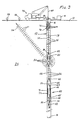
- FIG. 3 illustrates one application of the inflatable attenuator 40 in the method and system of the present invention.
- a seismic exploration van or truck 70 carrying a high-pressure compressor 75 lowers via cable 63 the impulsive energy source 20 which has suspended from the lower end thereof on a cable 68 the inflatable attenuator 40 which is positioned below the energy source 20 in the well 10.
- High pressure gas usually air, is fed from the pressurized gas source 75 via a high pressure hose line 80 to the energy source 20.
- the impulsive energy source 20 is a hydro gun as disclosed and claimed in U.S. Patent No. 4,234,052
- the primary sound waves 27 are propagated through the structure 25 of the Earth 12, as shown by the arrow 26, and reach the geophones or hydrophones 28 which receive these desired primary waves.
- the tube waves 32 travelling downwardly in the column of liquid 14 in the well 10 encounter the inflatable attenuator 40 which provides very poor sound coupling between the liquid 14 and the air-filled bladder 46.
- the tube waves 32 encounter the tapered upper end 43 of the inflated bladder 46, they are absorbed and damped by the elongated bladder for there is a relatively long path in the axial direction relative to the attenuator 40.
- the inflated bladder 46 (FIG. 2) essentially completely fills the perforated housing 46, and the wall of the bladder 46 is pressing radially outwardly being preferably spaced about 1/8th to about 1/2 of an inch from the inside surface of the perforated cylindrical housing 42.
- the openings or perforations 44 in the housing communicate with the inflatable bladder 46 which dissipates and attenuates or damps tube waves 32 in the narrow region 71 around the attenuator 40 and in the narrow annular region 77 (FIG. 2) between the bladder 46 and housing 42.
- the openings 44 have a size of about 3/16ths to about 5/16ths of an inch and comprise at least about 40% to about 60% of the total area of the housing 42.
- the tube waves 35 travelling to the top 16 of the liquid column 14 are attenuated using numerous bubbles 72 of air created by a low-pressure compressed air generator 73 feeding through a hose line 74 to an elongated porous probe 76 which discharges multitudes of compressed air bubbles 72 into the upper portion of the liquid column 14 creating a substantial column 78 of bubbles of various sizes and random spacing which dissipate the tube waves 35.
- tube waves 35 travelling upwardly in the liquid column are attenuated by bubbles 72 while tube waves 32 travelling downardly in the liquid column 14 are attenuated by the inflatable attenuator 40 allowing the phones 28 to receive only or mainly those desired primary waves 27 which are transmitted directly from the seismic energy source 20.
- the tube wave attenuator 40 is supplied with pressurized gas from the closely associated gas supply container 52.
- the tube wave attenuator 40 is supplied with pressurized gas from a source 75 on the Earth's surface 12.
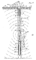
- FIG. 4 is similar to FIG. 3 except that high-pressure compressed gas, usually air; is supplied from the surface by a high-pressure hose line 80 extending to the energy source 20 and to the inflatable attenuator 40, thereby dispensing with the need for attaching the supply container 52 of compressed gas to the inflatable attenuator 40.
- a common source 75 of compressed air in the van is supplying both the impulsive energy source 20 and the inflatable attenuator 40 via hose line 80.
- this same source 75 may be used to supply the probe 76 to create a mass of air bubbles 78 near the top 16 of the column for attenuating upwardly traveling tube waves in that bubble mass 78.
- the separate single-stage low-pressure compressor 73 can be used to feed the probe 76.
- the compressor 75 is a high-pressure compressor, for example at least a triple-stage com pressor having an output pressure of at least 2,200 psi.
- the hose line 80 is connected through the pressure-reducing valve 48 to feed the interior of the bladder 46. The operation of the system in FIG. 4 and the method employed are the same as that shown in FIG. 3.
- FIG. 5 shows another embodiment of the method and system employing the use of an inflatable attenuator 40 both below as well as above the impulsive energy source 20.
- These two inflatable attenuators 40 are utilized to attenuate tube waves traveling down the liquid column 14 in the well 10 and to attenuate tube waves traveling upwardly in the liquid column from the energy source 20.
- the compressed gas source 75 is shown mounted in the seismic exploration van 70. Compressed gas is fed through the line 80 to the seismic energy source 20.
- each of the tube wave attenuators 40 has an associated nearby container 52 of compressed gas, usually air, for inflating the bladder through a pressure-regulating valve 48.
- FIG. 6 illustrates an alternative embodiment to FIG. 5 which utilizes a common pressurized gas supply 75 which feeds through a high pressure hose line 80 to the pressure-regulating valve 48 for inflatable bladder 46 of the upper attenuator 40.
- This hose line 80 also feeds to the energy source 20 and through a continuation of line 80 to the pressure-regulating valve 48 for the inflatable bladder 46 of the lower attenuator 40.
- the operation of the system and method of FIG. 6 are similar to those of FIG. 5 in that the upper attenuator 40 is used to attenuate upwardly traveling tube waves in the liquid column 14 while the lower attenuator 40 is used to attenuate tube waves traveling downwardly in this liquid column 14.
- An advantage of using a single gas supply line 80 for feeding the energy source 20 and the attenuators 40 as shown in FIG. 6 resides in the ability to carry on very numerous firings of the seismic source 20 at various elevations without withdrawing the equipment from the well, which would become necessary if the pressurized gas in one of the containers 52 (FIG.5) were to become dissipated during the seismic surveying operations and thus need to be replenished.
- the "pressurized gas" for charging the impulsive energy source 20 and for generating the bubbles 72 is usually compressed air.
- the pressurized gas may be compressed nitrogen or carbon dioxide.
- steam may be used to charge the energy source 20, and then a low-pressure compressor 73 is used to generate the gas bubbles 72.
- the container 52 of pressurized gas can advantageously be mounted inside of the bladder 46 by employing a container 52 which has a slim shape for providing an annular clearance space between the exterior of the pressure vessel 52 and the inside surface of the resilient, flexible wall of the bladder.
- the bladder remains resilient even though it houses the pressure vessel 52.
- the cables or chains 56 are attached to pad eyes (not shown) attached to the lower end fitting 45.
- the conduit 49 from the pressure vessel 52 extends down through the lower end fitting 45 and extends down to the pressure regulating valve 48, which is located below the lower end fitting 45.
- the exposed portion of the conduit 49 includes an accessible Tee coupling with a shut off valve (not shown) for enabling the pressure vessel to be conveniently refilled with pressurized gas whenever needed without removing the pressure vessel from inside of the bladder.
- FIGS. 7A and 7B show an inflatable attenuator 40A having a cylindrical inflatable lower bladder 46-2 and an upper inflatable bladder 46-1.
- the cylindrical lower bladder 46-2 is made of the same material as the generally cylindrical bladder 46 in FIG. 2.
- tough, durable, resilient non-reinforced polyurethane is the preferred material for the tapered upper bladder 46-1, because it is desirable to position the attenuator 40 or 40A relatively close to the energy source for attenuating the tube waves as reasonably close to the energy source as practicable. Therefore, the upper bladder 46-1 becomes subjected to a powerful, impulsive change in pressure each time that the energy source is fired. Tough, durable, resilient polyurethane proves to be able to withstand successfully the resultant sudden large stresses involved.
- the upper bladder 46-1 tapers or flares outwardly and downwardly, for example, it has a relatively elongated generally conical configuration.
- the support and axial trunk of this attenuator 40A comprises a strong rigid tube 90, for example, of steel, having a pipe-threaded socket 92 at its upper end.
- the attenuator 40A can be suspended in a well 10 by attaching a hose line 74 or 80 to the socket 92 by providing a threaded coupling on the lower end of the hose line 74 or 80 which screws into the socket 92.
- this attenuator 40A can be suspended below an energy source 20 in a well by extending a section of high pressure hose line 80 down from the energy source 20 and attaching it to the socket 92.
- the exterior surface of the axial tube frame 90 is threaded at 94 immediately below the socket 92, and a pair of clamp rings 96 encircle the upper end portion of the bladder 46-1 overlying this threaded region 94.
- a mounting seat member 98 for example, of steel, rigidly attached to the axial tube 90, for example, by welds at 100.
- the exterior surface of the seat member 98 is threaded in an upper region 94 for receiving the lower end portion of the tapered bladder 46-1 secured by a pair of clamping rings 96 and is also threaded in a lower region 94 for receiving the upper end portion of the cylindrical bladder 46-2 secured by another pair of clamp rings 96.
- a large O-ring 102 of resilient polymeric material for example, polyurethane is mounted in a retainer groove 104 between the two bladders 46-1 and 46-2 for serving as a bumper or protective annular shoulder.
- the lower bladder 46-2 is slid down over the seat member 98, and the O-ring bumper 102 is installed after the lower bladder 46-2 has been installed. Then, the upper bladder 46-1 is installed after the O-ring bumper 102 is in place.
- the axial tube frame 90 extends down a considerable distance below the mounting seat member 98 and is securely attached, for example, by welding 100, to a lower end fixture 106.
- the lower end of the cylindrical bladder 46-1 is firmly secured to an externally threaded region 94 of the fixture 106 by a pair of clamp rings 96.
- the bore 108 of the tube frame 90 communicates through a passageway 110 in the fixture 106 with a pressure-reducing and regulating valve 48.
- This regulating valve 48 is mounted in an axial socket 112 in the fixture 106, being retained by a removable retainer sleeve 114 which is held by a removable end fitting 116 fastened to the fixture 106 by machine screws 118.
- the pressure-reducing valve 48 is sealed to the passageway 110 by an O-ring 120.
- the pressurized gas, usually compressed air, of regulated pressure is fed from the valve 48 through a passageway 122 in the fixture 106 communicating with the interior of the bladder 46-2, and an O-ring 124 seals the valve 48 to the passageway 122.
- the interior of the bladder 46-2 communicates with the interior of the bladder 46-1 through a passageway 126 in the mounting seat member 98.
- the valve 48 supplies both bladders with pressurized gas at the desired pressure compared with ambient, for example, about 1 to about 8 p.s.i. above ambient.
- a particle filter 130 is held in the passage 128 by a snap ring 132; this filter 130 comprises a fibrous mat sandwiched between two discs each having numerous apertures.
- adjustable pressure-reducing and regulating valve 48 is also a self-venting valve set to vent at a pressure above the regulated pressure, for example, set to vent at about 12 p.s.i., then a pressure-relief valve is not needed.
- a pressure-relief valve 50 is included, it is mounted in a transverse socket 134 communicating through a passage 136 with the passage 122 communicating with the interior of the bladders 46-1 and 46-2. The other end of the drilled passage 136 is plugged at 138.
- the pressure-relief valve 50 is held in its socket 134 by a threaded ring 140 and communicates with ambient liquid through a port 142 in this ring.
- fixture 106 is enlarged in diameter below the region 94 where the bladder 46-2 is attached, and this enlargement serves as a protective annular shoulder below the lower end of the bladder for preventing abrasion of the bladder 46-2 against the well wall.
- pressurized gas usually compressed air
- supplied into the socket 92 feeds down through the bore 108 of the tubular support 90 and feeds through passage 110 to the pressure-reducing and regulating valve 48.
- Pressurized gas at the desired pressure level relative to the pressure of ambient liquid is supplied by the valve 48 through the passageway 122 into the interiors of the two bladders.
- the pressure relief valve 50 bleeds away pressurized gas from the passageways 122, 136 through the port 142 to ambient. If the valve 48 is self-venting, then pressurized gas bleeds away from the passageway 122 through the valve 48 through the axial passage 128 and through the filter 130 to ambient.
- phones is intended to include geophones and hydrophones.
- the attenuation method, system and apparatus of the present invention are very effective and advantageous in eliminating or dramatically reducing the problems caused by unwanted tube waves occurring in a well when using an impulsive seismic energy (sound) source in a liquid-containing well in the earth for seismic surveying of the structure of the Earth around the well.
- the energy source 20 is a vibrator, and if a vibrator causes tube waves in the liquid-containing well, then the present inveniton may be used to advantage with such a vibrator energy source.
Landscapes
- Physics & Mathematics (AREA)
- Engineering & Computer Science (AREA)
- Life Sciences & Earth Sciences (AREA)
- Geology (AREA)
- Geophysics (AREA)
- Environmental & Geological Engineering (AREA)
- Acoustics & Sound (AREA)
- Mining & Mineral Resources (AREA)
- General Life Sciences & Earth Sciences (AREA)
- Multimedia (AREA)
- Fluid Mechanics (AREA)
- Geochemistry & Mineralogy (AREA)
- Remote Sensing (AREA)
- General Physics & Mathematics (AREA)
- Supply Devices, Intensifiers, Converters, And Telemotors (AREA)
- Geophysics And Detection Of Objects (AREA)
- Pipe Accessories (AREA)
Applications Claiming Priority (4)
| Application Number | Priority Date | Filing Date | Title |
|---|---|---|---|
| US2320887A | 1987-03-09 | 1987-03-09 | |
| US23208 | 1987-03-09 | ||
| US07/038,327 US4858718A (en) | 1987-03-09 | 1987-04-14 | Tube-wave attenuation method, system and apparatus for use with an inpulsive seismic energy source in liquid-containing wells |
| US38327 | 2002-01-02 |
Publications (2)
| Publication Number | Publication Date |
|---|---|
| EP0281946A2 true EP0281946A2 (de) | 1988-09-14 |
| EP0281946A3 EP0281946A3 (de) | 1989-08-30 |
Family
ID=26696849
Family Applications (1)
| Application Number | Title | Priority Date | Filing Date |
|---|---|---|---|
| EP88103279A Withdrawn EP0281946A3 (de) | 1987-03-09 | 1988-03-03 | Rohrwellendämpfungsverfahren, System und Gerät zur Anwendung in mit Flüssigkeit gefüllten Bohrlöchern |
Country Status (3)
| Country | Link |
|---|---|
| US (1) | US4858718A (de) |
| EP (1) | EP0281946A3 (de) |
| JP (1) | JPS63282683A (de) |
Cited By (10)
| Publication number | Priority date | Publication date | Assignee | Title |
|---|---|---|---|---|
| GB2280958A (en) * | 1993-08-06 | 1995-02-15 | Exxon Production Research Co | Apparatus for generating seismic waves |
| FR2714486A1 (fr) * | 1993-12-29 | 1995-06-30 | Inst Francais Du Petrole | Méthode et dispositif de prospection sismique dans des puits permettant un filtrage des ondes guidées. |
| GB2305244A (en) * | 1995-09-13 | 1997-04-02 | Schlumberger Ltd | Attenuator for borehole acoustic waves |
| GB2309525A (en) * | 1993-12-29 | 1997-07-30 | Inst Francais Du Petrole | Attenuating tube waves in seismic well prospecting |
| GB2324371A (en) * | 1997-04-14 | 1998-10-21 | Inst Francais Du Petrole | Tube wave attenuation in elastic wave exploration tools |
| WO1999005545A1 (en) * | 1997-07-28 | 1999-02-04 | Groundflow Limited | Enhanced detection method |
| US6597633B1 (en) | 1999-03-18 | 2003-07-22 | Groundflow Limited | Method for electrolinetic downhole logging |
| EP1359366A1 (de) * | 2002-04-23 | 2003-11-05 | Young Engineering Manufacturing, Inc. | Druckpulsationsdämpfer und Dämpfungssystem |
| US6842697B1 (en) | 1999-03-18 | 2005-01-11 | Groundflow Ltd. | Method for downhole logging |
| CN109915111A (zh) * | 2019-03-15 | 2019-06-21 | 中国地质大学(武汉) | 一种基于纳米材料的冲击式煤层气两相流气泡传感器 |
Families Citing this family (24)
| Publication number | Priority date | Publication date | Assignee | Title |
|---|---|---|---|---|
| FR2618910B1 (fr) * | 1987-07-28 | 1989-10-27 | Inst Francais Du Petrole | Methode et dispositif pour ameliorer le coefficient de transmission aux formations geologiques de l'energie creee par une source sismique de puits |
| FR2669740B1 (fr) * | 1990-11-27 | 1993-04-02 | Geophysique Cie Gle | Dispositif pour attenuer les ondes de stoneley dans un puits. |
| US5171943A (en) * | 1991-01-23 | 1992-12-15 | Balogh William T | Tubewave damper probe for seismic applications |
| US5170018A (en) * | 1991-02-19 | 1992-12-08 | Exxon Production Research Company | Method and apparatus for tube-wave suppression |
| US5109946A (en) * | 1991-04-11 | 1992-05-05 | Omnitech Services Inc. | Apparatus for pack-off locking of seismic energy source |
| US5510582A (en) * | 1995-03-06 | 1996-04-23 | Halliburton Company | Acoustic attenuator, well logging apparatus and method of well logging |
| US6196350B1 (en) | 1999-10-06 | 2001-03-06 | Tomoseis Corporation | Apparatus and method for attenuating tube waves in a borehole |
| US6193010B1 (en) * | 1999-10-06 | 2001-02-27 | Tomoseis Corporation | System for generating a seismic signal in a borehole |
| US6951262B2 (en) * | 2002-03-05 | 2005-10-04 | Battelle Energy Alliance, Llc | Method and apparatus for suppressing waves in a borehole |
| US6776255B2 (en) * | 2002-11-19 | 2004-08-17 | Bechtel Bwxt Idaho, Llc | Methods and apparatus of suppressing tube waves within a bore hole and seismic surveying systems incorporating same |
| US7467685B2 (en) * | 2004-05-25 | 2008-12-23 | Schlumberger Technology Corporation | Array seismic fluid transducer source |
| US7269099B2 (en) * | 2004-07-30 | 2007-09-11 | Bolt Technology Corporation | Air gun |
| CA2648418C (en) | 2006-04-06 | 2016-01-05 | Weatherford/Lamb, Inc. | Improved performance of permanently installed tubing conveyed seismic arrays using passive acoustic absorbers |
| US7874362B2 (en) * | 2007-03-26 | 2011-01-25 | Schlumberger Technology Corporation | Determination of downhole pressure while pumping |
| US9103203B2 (en) * | 2007-03-26 | 2015-08-11 | Schlumberger Technology Corporation | Wireless logging of fluid filled boreholes |
| US8113278B2 (en) | 2008-02-11 | 2012-02-14 | Hydroacoustics Inc. | System and method for enhanced oil recovery using an in-situ seismic energy generator |
| US9348042B2 (en) | 2011-12-27 | 2016-05-24 | Cgg Services Sa | Buried pressurized volumetric source and method |
| US9581705B2 (en) * | 2012-10-15 | 2017-02-28 | Stephen Chelminski | System and method for producing high quality seismic records within bore holes |
| US10031245B2 (en) * | 2013-02-24 | 2018-07-24 | Stephen Chelminski | Device for marine seismic explorations for deposits |
| US8971152B2 (en) * | 2013-02-24 | 2015-03-03 | Stephen Chelminski | Device for marine seismic explorations for deposits |
| US9611724B2 (en) * | 2013-08-23 | 2017-04-04 | Halliburton Energy Services Inc. | Damping pressure pulses in a well system |
| EP3289163B1 (de) * | 2015-04-29 | 2021-06-02 | ConocoPhillips Company | Bohrlochträgheitsmassensystem |
| US9804280B2 (en) | 2015-10-17 | 2017-10-31 | Stephen Chelminski | Method and apparatus for tuning the rise time of the initial pulse of an air gun |
| US11774619B2 (en) | 2019-01-14 | 2023-10-03 | Halliburton Energy Services, Inc. | Reduction of a tool wave excited by a transmitter of a well logging tool |
Family Cites Families (15)
| Publication number | Priority date | Publication date | Assignee | Title |
|---|---|---|---|---|
| US3126976A (en) * | 1964-03-31 | Seismic velocity logging of low-velocity | ||
| US3054471A (en) * | 1960-01-15 | 1962-09-18 | California Research Corp | Acoustic filters for attenuating vertically propagated interference in borehole seismology |
| US3601216A (en) * | 1967-10-23 | 1971-08-24 | Mandrel Industries | System for suppressing multiple pulse in marine seismic sources by injection of additional air |
| US3718205A (en) * | 1970-06-22 | 1973-02-27 | D Fair | Bore hole seismic transducer |
| US3982606A (en) * | 1975-01-22 | 1976-09-28 | Mobil Oil Corporation | Acoustical logging apparatus having signal delay means |
| US3997021A (en) * | 1975-05-16 | 1976-12-14 | Bolt Associates, Inc. | Pressurized gas discharging apparatus for use as a down-bore seismic impulse source |
| US4234052A (en) * | 1978-11-13 | 1980-11-18 | Bolt Associates, Inc. | Method and apparatus for generating seismic impulses using high pressure water pump as the energizing source |
| JPS57179777A (en) * | 1981-04-30 | 1982-11-05 | Oyo Chishitsu Kk | Filter tube for velocity detecting sonde |
| US4472794A (en) * | 1981-06-01 | 1984-09-18 | Bolt Technology Corporation | Sleeve shuttle air gun |
| US4497388A (en) * | 1981-08-25 | 1985-02-05 | Gaulin Corporation | Pulsation dampener and acoustic attenuator |
| US4739857A (en) * | 1981-11-27 | 1988-04-26 | Atlantic Richfield Company | Seismic source using self-propelled projectile |
| US4722417A (en) * | 1983-09-29 | 1988-02-02 | Hydroacustics, Inc. | Seismic wave generation by a downhole source |
| US4611685A (en) * | 1984-06-07 | 1986-09-16 | Exxon Production Research Co. | Acoustic logging in low velocity formations |
| US4671379A (en) * | 1985-09-03 | 1987-06-09 | Petrophysical Services, Inc. | Method and apparatus for generating seismic waves |
| FR2591756B1 (fr) * | 1985-12-16 | 1988-05-13 | Commissariat Energie Atomique | Sonde sismique notamment utilisable dans un puits de forage non tube |
-
1987
- 1987-04-14 US US07/038,327 patent/US4858718A/en not_active Expired - Fee Related
-
1988
- 1988-03-03 EP EP88103279A patent/EP0281946A3/de not_active Withdrawn
- 1988-03-09 JP JP63055915A patent/JPS63282683A/ja active Pending
Cited By (18)
| Publication number | Priority date | Publication date | Assignee | Title |
|---|---|---|---|---|
| GB2280958B (en) * | 1993-08-06 | 1996-12-04 | Exxon Production Research Co | Apparatus for generating seismic waves in a borehole |
| GB2280958A (en) * | 1993-08-06 | 1995-02-15 | Exxon Production Research Co | Apparatus for generating seismic waves |
| GB2285685B (en) * | 1993-12-29 | 1997-12-17 | Inst Francais Du Petrole | A method and a device for performing prospecting operations in a well |
| FR2714486A1 (fr) * | 1993-12-29 | 1995-06-30 | Inst Francais Du Petrole | Méthode et dispositif de prospection sismique dans des puits permettant un filtrage des ondes guidées. |
| NL9402217A (nl) * | 1993-12-29 | 1995-07-17 | Inst Francais Du Petrole | Werkwijze en inrichting voor seismisch onderzoek in putten, die een filteren van geleide golven mogelijk maken. |
| GB2285685A (en) * | 1993-12-29 | 1995-07-19 | Inst Francais Du Petrole | Attenuating tube waves in seismic well prospecting |
| GB2309525A (en) * | 1993-12-29 | 1997-07-30 | Inst Francais Du Petrole | Attenuating tube waves in seismic well prospecting |
| GB2309525B (en) * | 1993-12-29 | 1997-12-17 | Inst Francais Du Petrole | A method and a device for performing prospecting operations in a well |
| GB2305244B (en) * | 1995-09-13 | 1998-10-07 | Schlumberger Ltd | Attenuator for borehole acoustic waves |
| GB2305244A (en) * | 1995-09-13 | 1997-04-02 | Schlumberger Ltd | Attenuator for borehole acoustic waves |
| GB2324371A (en) * | 1997-04-14 | 1998-10-21 | Inst Francais Du Petrole | Tube wave attenuation in elastic wave exploration tools |
| GB2324371B (en) * | 1997-04-14 | 2001-01-03 | Inst Francais Du Petrole | Elastic wave exploration tools for wells |
| WO1999005545A1 (en) * | 1997-07-28 | 1999-02-04 | Groundflow Limited | Enhanced detection method |
| US6452395B1 (en) | 1997-07-28 | 2002-09-17 | Court Services Limited | Enhanced detection method |
| US6597633B1 (en) | 1999-03-18 | 2003-07-22 | Groundflow Limited | Method for electrolinetic downhole logging |
| US6842697B1 (en) | 1999-03-18 | 2005-01-11 | Groundflow Ltd. | Method for downhole logging |
| EP1359366A1 (de) * | 2002-04-23 | 2003-11-05 | Young Engineering Manufacturing, Inc. | Druckpulsationsdämpfer und Dämpfungssystem |
| CN109915111A (zh) * | 2019-03-15 | 2019-06-21 | 中国地质大学(武汉) | 一种基于纳米材料的冲击式煤层气两相流气泡传感器 |
Also Published As
| Publication number | Publication date |
|---|---|
| US4858718A (en) | 1989-08-22 |
| JPS63282683A (ja) | 1988-11-18 |
| EP0281946A3 (de) | 1989-08-30 |
Similar Documents
| Publication | Publication Date | Title |
|---|---|---|
| US4858718A (en) | Tube-wave attenuation method, system and apparatus for use with an inpulsive seismic energy source in liquid-containing wells | |
| US6196350B1 (en) | Apparatus and method for attenuating tube waves in a borehole | |
| US7468932B2 (en) | System for noise attenuation in marine seismic streamers | |
| US6879546B2 (en) | Gel-filled seismic streamer cable | |
| US4809243A (en) | Streamer cable | |
| AU2007201880B2 (en) | System for reducing towing noise in marine seismic survey streams | |
| RU2104564C1 (ru) | Устройство для проведения морских сейсморазведочных работ (варианты) и устройство обеспечения плавучести для сейсмических источников (варианты) | |
| US7298672B1 (en) | Marine seismic streamer having acoustic isolation between strength members and sensor mounting | |
| US4955012A (en) | Seismic streamer cable | |
| US5724311A (en) | Method and device for the long-term seismic monitoring of an underground area containing fluids | |
| US20060193203A1 (en) | Apparatus for attenuating noise in marine seismic streamers | |
| US5031719A (en) | Seismic sonde | |
| GB2297105A (en) | Riser assembly | |
| CN109073771B (zh) | 用于地震数据采集的可变浮力控制和回收系统 | |
| US20080186803A1 (en) | Fluid filled sensor mount for gel-filled streamer and streamer made therewith | |
| US5646379A (en) | Attentuator for borehole acoustic waves | |
| US4736345A (en) | Compliant spacer for a marine seismic streamer | |
| CN86102257A (zh) | 分布式海洋地震源控制系统和方法 | |
| US3893065A (en) | Hydrophone array | |
| RU2718146C2 (ru) | Способ компоновки и развертывания морского вибратора | |
| US20030173143A1 (en) | Method and apparatus for suppressing waves in a borehole | |
| US5459695A (en) | Seismic cable with reusable skin | |
| US4837751A (en) | Shielded hydrophone assembly | |
| US5404340A (en) | Marine seismic streamer with a device for damping oscillations | |
| US5523983A (en) | Dual rope vibration isolation module for towed hydrophone streamer |
Legal Events
| Date | Code | Title | Description |
|---|---|---|---|
| PUAI | Public reference made under article 153(3) epc to a published international application that has entered the european phase |
Free format text: ORIGINAL CODE: 0009012 |
|
| AK | Designated contracting states |
Kind code of ref document: A2 Designated state(s): DE FR GB NL |
|
| PUAL | Search report despatched |
Free format text: ORIGINAL CODE: 0009013 |
|
| AK | Designated contracting states |
Kind code of ref document: A3 Designated state(s): DE FR GB NL |
|
| STAA | Information on the status of an ep patent application or granted ep patent |
Free format text: STATUS: THE APPLICATION IS DEEMED TO BE WITHDRAWN |
|
| 18D | Application deemed to be withdrawn |
Effective date: 19900305 |