EP0282048A2 - Dispositif pour le traitement de matériaux de recyclage, de préférence de décombres - Google Patents
Dispositif pour le traitement de matériaux de recyclage, de préférence de décombres Download PDFInfo
- Publication number
- EP0282048A2 EP0282048A2 EP88103760A EP88103760A EP0282048A2 EP 0282048 A2 EP0282048 A2 EP 0282048A2 EP 88103760 A EP88103760 A EP 88103760A EP 88103760 A EP88103760 A EP 88103760A EP 0282048 A2 EP0282048 A2 EP 0282048A2
- Authority
- EP
- European Patent Office
- Prior art keywords
- air
- blow
- classifying
- screening
- opening
- Prior art date
- Legal status (The legal status is an assumption and is not a legal conclusion. Google has not performed a legal analysis and makes no representation as to the accuracy of the status listed.)
- Granted
Links
Images


Classifications
-
- B—PERFORMING OPERATIONS; TRANSPORTING
- B07—SEPARATING SOLIDS FROM SOLIDS; SORTING
- B07B—SEPARATING SOLIDS FROM SOLIDS BY SIEVING, SCREENING, SIFTING OR BY USING GAS CURRENTS; SEPARATING BY OTHER DRY METHODS APPLICABLE TO BULK MATERIAL, e.g. LOOSE ARTICLES FIT TO BE HANDLED LIKE BULK MATERIAL
- B07B4/00—Separating solids from solids by subjecting their mixture to gas currents
- B07B4/02—Separating solids from solids by subjecting their mixture to gas currents while the mixtures fall
-
- B—PERFORMING OPERATIONS; TRANSPORTING
- B03—SEPARATION OF SOLID MATERIALS USING LIQUIDS OR USING PNEUMATIC TABLES OR JIGS; MAGNETIC OR ELECTROSTATIC SEPARATION OF SOLID MATERIALS FROM SOLID MATERIALS OR FLUIDS; SEPARATION BY HIGH-VOLTAGE ELECTRIC FIELDS
- B03B—SEPARATING SOLID MATERIALS USING LIQUIDS OR USING PNEUMATIC TABLES OR JIGS
- B03B9/00—General arrangement of separating plant, e.g. flow sheets
- B03B9/06—General arrangement of separating plant, e.g. flow sheets specially adapted for refuse
- B03B9/061—General arrangement of separating plant, e.g. flow sheets specially adapted for refuse the refuse being industrial
- B03B9/065—General arrangement of separating plant, e.g. flow sheets specially adapted for refuse the refuse being industrial the refuse being building rubble
-
- B—PERFORMING OPERATIONS; TRANSPORTING
- B07—SEPARATING SOLIDS FROM SOLIDS; SORTING
- B07B—SEPARATING SOLIDS FROM SOLIDS BY SIEVING, SCREENING, SIFTING OR BY USING GAS CURRENTS; SEPARATING BY OTHER DRY METHODS APPLICABLE TO BULK MATERIAL, e.g. LOOSE ARTICLES FIT TO BE HANDLED LIKE BULK MATERIAL
- B07B9/00—Combinations of apparatus for screening or sifting or for separating solids from solids using gas currents; General arrangement of plant, e.g. flow sheets
-
- Y—GENERAL TAGGING OF NEW TECHNOLOGICAL DEVELOPMENTS; GENERAL TAGGING OF CROSS-SECTIONAL TECHNOLOGIES SPANNING OVER SEVERAL SECTIONS OF THE IPC; TECHNICAL SUBJECTS COVERED BY FORMER USPC CROSS-REFERENCE ART COLLECTIONS [XRACs] AND DIGESTS
- Y02—TECHNOLOGIES OR APPLICATIONS FOR MITIGATION OR ADAPTATION AGAINST CLIMATE CHANGE
- Y02W—CLIMATE CHANGE MITIGATION TECHNOLOGIES RELATED TO WASTEWATER TREATMENT OR WASTE MANAGEMENT
- Y02W30/00—Technologies for solid waste management
- Y02W30/50—Reuse, recycling or recovery technologies
- Y02W30/52—Mechanical processing of waste for the recovery of materials, e.g. crushing, shredding, separation or disassembly
-
- Y—GENERAL TAGGING OF NEW TECHNOLOGICAL DEVELOPMENTS; GENERAL TAGGING OF CROSS-SECTIONAL TECHNOLOGIES SPANNING OVER SEVERAL SECTIONS OF THE IPC; TECHNICAL SUBJECTS COVERED BY FORMER USPC CROSS-REFERENCE ART COLLECTIONS [XRACs] AND DIGESTS
- Y02—TECHNOLOGIES OR APPLICATIONS FOR MITIGATION OR ADAPTATION AGAINST CLIMATE CHANGE
- Y02W—CLIMATE CHANGE MITIGATION TECHNOLOGIES RELATED TO WASTEWATER TREATMENT OR WASTE MANAGEMENT
- Y02W30/00—Technologies for solid waste management
- Y02W30/50—Reuse, recycling or recovery technologies
- Y02W30/58—Construction or demolition [C&D] waste
Definitions
- the invention relates to a device for the reprocessing of granular to lumpy and contaminated recycling materials, preferably building rubble, which after disintegration, preferably in an impact mill, is broken down into different fractions and preferably subjected to a screening process by means of vibrating conveyors with a layer thickness that is uniform over the entire conveyor cross section to which the entire visible material is fed into a controllable visible air flow generated by a fan, which discharges the contaminants from the falling material due to their lower specific weight and / or their larger blowing area and feeds them to a collection chamber separated from the fractions.
- the classifying air has to flow upwards at a sufficiently high speed in the classifying room in order to discharge the contaminants upwards due to their lower specific weight and / or their larger blowing area.
- This not only requires a high expenditure of energy, but also carries the risk that reusable components of the recycling materials with the impurities are carried upward out of the viewing area.
- the adjustment of the visual limit is therefore difficult with these known devices.
- they have the disadvantage that the entire classifying air has to be dedusted in downstream filters, because it is inevitable due to the countercurrent classifying that the classifying air is exposed to a high level of dust.
- the invention has for its object to develop a device of the type described in such a way that there is a flawless separation between the individual fractions of recycled materials and the contaminants, which in turn can be classified for further processing or combustion with considerably less energy.
- the solution to this problem by the invention is characterized in that in the viewing space below the task for the visible material, at least one exhaust nozzle for the viewing air is provided which extends across the entire width of the visible space and which is transverse to the direction of movement of the falling material and into one in the opposite Wall of the viewing space trained opening is aligned to which a visual air relaxation chamber for which the contaminant is laterally discharged, which is provided at the bottom with a discharge opening for the contaminants.
- This inventive design results in a device that allows reliable removal of contaminants with little technical effort, without having to spend a lot of energy because the contaminants are not discharged in a countercurrent process, but by side discharge from the viewing area, which is significantly less Air speeds required. After the sifting air loaded with the impurities enters the sifting air relaxation chamber, the impurities fall down in this chamber so that they can be removed from the discharge opening arranged there, while the sifting air is ready for return to the sifting process.
- blowing nozzles In order not only to turn elongated contaminants, such as pieces of wood, for example, from the side blowing on falling, but also to discharge them laterally, it is proposed according to a further feature of the invention to arrange at least two blowing nozzles at a distance from one another below the task in the viewing area. These at least two blow-out nozzles also reliably detect elongated contaminants.
- the blow-out nozzles can be made adjustable with regard to their blow-out direction and / or their blow-out cross-section, in order to be able to adjust the visual effect and to be able to adapt to different feed materials.
- At least the lower part of the opening in the transition between the viewing area and the viewing air relaxation chamber can be formed by adjustable guide plates. This also makes it possible to adapt the visual result to the prevailing ge conditions possible, since the discharge cross-section and the lower edge of the opening can be adapted to the prevailing conditions by adjusting the guide plates.
- the sifting air relaxation chamber is connected to the fan by means of an air duct to form a substantially closed sifting air circuit.
- the invention finally proposes to arrange a dust filter for part of the circulated visual air in a branch duct running parallel to the air duct.
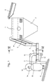
- the device for the reprocessing of recycling materials shown on the basis of an exemplary embodiment comprises a vibrating sieve 1 to which the material to be reprocessed is connected Conveyor belt 2 is fed.
- the material fed in the exemplary embodiment is broken down into four fractions, for example into a first fraction with maximum dimensions between 0 and 8 mm, a second fraction with dimensions between 8 and 16 mm, a third fraction with dimensions between 16 and 32 mm and a fourth fraction with dimensions over 32 mm.
- the first fraction is drawn off directly from the funnel-shaped outlet 3 of the vibrating screen 1.
- the second fraction reaches a middle outlet channel 4, the third fraction in a side outlet channel 5 and the fourth fraction also in a side outlet channel 6.
- These channels 4, 5 and 6, which merge into a horizontal section guide the three coarser fractions while at the same time equalizing the Layer thickness by means of the channel sections designed as vibratory conveyors to a viewing space 7, which is drawn in an enlarged sectional view in FIG.
- blow-out nozzles 8 for the classifying air are arranged in the classroom 7 below the task for the classifying material in the exemplary embodiment. These blow-out nozzles 8 are aligned transversely to the direction of movement of the material falling into the viewing space 7 and to an opening 9 formed in the opposite wall of the viewing space 7. Via this opening 9, the viewing space 7 is connected to a classifying air relaxation chamber 10, which is provided at the bottom with a discharge opening 11.
- a blown air jet is blown out through the blower nozzles 8 and is generated by a fan 12 and is supplied to the blower nozzles 8 via pressure lines 13.
- the three coarser Frak tion contained contaminants, especially wood and plastic parts laterally deflected. While the fractions in the respective shaft of the viewing space 7 fall down and are discharged via separate conveyor belts, the contaminants with the viewing air reach the viewing air relaxation chamber 10 because the air speed in this viewing air relaxation chamber 10 drops considerably due to the larger volume , in this classifying air expansion chamber 10 the contaminants fall out of the classifying air so that they can be withdrawn via the discharge opening 11.
- the visual air freed from impurities in this way is returned to the fan 12 via a suction line 14 in a closed circuit.
- a partial flow of the sight air circulated in the closed circuit can be branched off from the pressure line 13 and fed via a filter line 15 to a dust filter (not shown in the drawing).
- the dust-free visual air can either be blown outside or returned to the circuit.
- the filter line 15 represents the branch duct of a bypass system.
- the Fig.5 shows that the lower part of the opening 9 is formed in the transition between the viewing space 7 and the viewing air relaxation chamber 10 by a baffle 16, which is adjustable to change the opening cross section in height, so that the device optimally to that each material to be processed can be adjusted.
Landscapes
- Combined Means For Separation Of Solids (AREA)
Applications Claiming Priority (2)
| Application Number | Priority Date | Filing Date | Title |
|---|---|---|---|
| DE19873708180 DE3708180A1 (de) | 1987-03-13 | 1987-03-13 | Vorrichtung zur wiederaufbereitung von recyclingstoffen, vorzugsweise bauschutt |
| DE3708180 | 1987-03-13 |
Publications (3)
| Publication Number | Publication Date |
|---|---|
| EP0282048A2 true EP0282048A2 (fr) | 1988-09-14 |
| EP0282048A3 EP0282048A3 (en) | 1989-06-07 |
| EP0282048B1 EP0282048B1 (fr) | 1991-07-31 |
Family
ID=6322992
Family Applications (1)
| Application Number | Title | Priority Date | Filing Date |
|---|---|---|---|
| EP19880103760 Expired - Lifetime EP0282048B1 (fr) | 1987-03-13 | 1988-03-10 | Dispositif pour le traitement de matériaux de recyclage, de préférence de décombres |
Country Status (2)
| Country | Link |
|---|---|
| EP (1) | EP0282048B1 (fr) |
| DE (2) | DE3708180A1 (fr) |
Cited By (1)
| Publication number | Priority date | Publication date | Assignee | Title |
|---|---|---|---|---|
| EP0599801A1 (fr) * | 1992-11-27 | 1994-06-01 | SBM WAGENEDER Gesellschaft m.b.H. | Procédé pour le traitement de décombres et installation pour la mise en oeuvre du procédé |
Families Citing this family (7)
| Publication number | Priority date | Publication date | Assignee | Title |
|---|---|---|---|---|
| AT396878B (de) * | 1991-05-16 | 1993-12-27 | Binder Co Ag | Verfahren zum absaugen von fremdkörpern aus einem schüttgutstrom |
| DE4413288C2 (de) * | 1994-04-16 | 1996-05-15 | Albert Sax | Vorrichtung zur Selektion von Bauschutt |
| DE19500207C1 (de) * | 1995-01-05 | 1996-08-14 | Wolfgang Adamski | Verfahren und Anlage zur Trennung von Bauschutt |
| DE19505385A1 (de) * | 1995-02-17 | 1996-08-22 | Rethmann Kreislaufwirtsch Gmbh | Verfahren und Vorrichtung zum Sortieren von Abfall, insbesondere Baumischabfall |
| DE29718973U1 (de) | 1997-10-24 | 1998-02-19 | LKS Luft- und Klimaservice Christian Israel, 09125 Chemnitz | Vorrichtung zur Entstaubung von Schüttgut |
| CZ303233B6 (cs) * | 2006-01-12 | 2012-06-06 | Výzkumný ústav zemedelské techniky, v.v.i. | Odsávací zarízení |
| DE102020004891A1 (de) | 2020-08-11 | 2022-02-17 | Allgaier Werke Gmbh | System und Verfahren zur gravimetrischen Sortierung eines Stoffgemischs |
Family Cites Families (7)
| Publication number | Priority date | Publication date | Assignee | Title |
|---|---|---|---|---|
| DE805202C (de) * | 1948-12-22 | 1951-05-10 | Gustav Brueser Maschinenfabrik | Erbsenreinigungsmaschine |
| CH465534A (de) * | 1963-12-20 | 1968-11-30 | Rumpf Hans Prof Ing Dr | Verfahren und Vorrichtung zum Sichten von körnigem Gut im Querstrom |
| DE2527000A1 (de) * | 1975-06-18 | 1976-12-30 | Formmaschinen Gmbh Lufttechnik | Sortieranlage zum sortieren von materialien von unterschiedlicher schwebegeschwindigkeit |
| DE2929142A1 (de) * | 1979-07-19 | 1981-02-05 | Babcock Krauss Maffei Ind | Verfahren und vorrichtung zum sichten von grobkoernigem gut in einem horizontalsichtstrom |
| SE439122C (sv) * | 1981-01-29 | 1987-07-27 | Forsberg G L K | Vindsiktningsanordning |
| US4441995A (en) * | 1983-05-12 | 1984-04-10 | Reclamet, Inc. | Chunk separator and process of separation for machine tool scrap |
| EP0161327B1 (fr) * | 1984-05-17 | 1988-08-24 | TPT TECHNOLOGIES S.p.A. | Dispositif séparateur pour la séparation des composants de farines alimentaires ou analoques |
-
1987
- 1987-03-13 DE DE19873708180 patent/DE3708180A1/de not_active Withdrawn
-
1988
- 1988-03-10 DE DE8888103760T patent/DE3863945D1/de not_active Expired - Lifetime
- 1988-03-10 EP EP19880103760 patent/EP0282048B1/fr not_active Expired - Lifetime
Cited By (1)
| Publication number | Priority date | Publication date | Assignee | Title |
|---|---|---|---|---|
| EP0599801A1 (fr) * | 1992-11-27 | 1994-06-01 | SBM WAGENEDER Gesellschaft m.b.H. | Procédé pour le traitement de décombres et installation pour la mise en oeuvre du procédé |
Also Published As
| Publication number | Publication date |
|---|---|
| EP0282048B1 (fr) | 1991-07-31 |
| DE3863945D1 (de) | 1991-09-05 |
| DE3708180A1 (de) | 1988-09-22 |
| EP0282048A3 (en) | 1989-06-07 |
Similar Documents
| Publication | Publication Date | Title |
|---|---|---|
| EP0303034B1 (fr) | Procédé et dispositif pour le tri de déchets | |
| EP0282943B1 (fr) | Procédé et dispositif pour récupérer du verre de déchets de verre | |
| EP0636322A2 (fr) | Dispositif de transport pour la formation d'une couche uniforme | |
| DE2510694C2 (de) | Verfahren und Anlage zum Wiedergewinnen von Papier aus Papier enthaltenden Abfällen | |
| EP0282048B1 (fr) | Dispositif pour le traitement de matériaux de recyclage, de préférence de décombres | |
| EP0983803A1 (fr) | Procédé et dispositif pour séparer des matières à faculté d' écoulement | |
| EP0809543B1 (fr) | Procede et dispositif pour trier des dechets, notamment des dechets melanges provenant de la construction | |
| DE19501263C2 (de) | Verfahren und Vorrichtung zur Sichtung eines Materialien-Gemisches | |
| DE10054418B4 (de) | Verfahren und Vorrichtung zur Entfernung von staubförmigen und faserigen Beimengungen aus Schüttgut | |
| DE3245231C2 (fr) | ||
| DE4106831C1 (fr) | ||
| DE4413288C2 (de) | Vorrichtung zur Selektion von Bauschutt | |
| DE102016117383B4 (de) | Sichter | |
| DE8703776U1 (de) | Vorrichtung zur Wiederaufbereitung von Recyclingstoffen, vorzugsweise Bauschutt | |
| EP0125620A1 (fr) | Système de filtrage d'air | |
| DE2433514C2 (de) | Vorrichtung zur Abscheidung von Pulvern und Stäuben | |
| DE4220598A1 (de) | Verfahren und vorrichtung zur ausscheidung von leichten fremdstoffen | |
| DE2641068A1 (de) | Steigrohrwindsichter zur entsandung von holzspaenen | |
| DE19717093C2 (de) | Verfahren und Vorrichtung zur Abscheidung von Verunreinigungen aus Gesteinsbrocken | |
| DE102012010030B4 (de) | Verfahren und vorrichtung zur trennung eines heterogenen materialstroms in mindestens zwei materialfraktionen | |
| DE683938C (de) | Verfahren und Vorrichtung zum Abtrennen des Feinststaubes aus feinem Gut von im wesentlichen 0 bis 2 mm Korngroesse | |
| DE102020103233A1 (de) | Windstreukammer und Verfahren zum Streuen und Formen eines rieselfähigen Materials auf einem Formband | |
| EP0081087A2 (fr) | Procédé et dispositif pour séparer des matières en vrac suivant la densité | |
| DE1507686B1 (de) | Steigrohr-Windsichter | |
| CH674162A5 (fr) |
Legal Events
| Date | Code | Title | Description |
|---|---|---|---|
| PUAI | Public reference made under article 153(3) epc to a published international application that has entered the european phase |
Free format text: ORIGINAL CODE: 0009012 |
|
| AK | Designated contracting states |
Kind code of ref document: A2 Designated state(s): BE DE FR GB IT NL |
|
| PUAL | Search report despatched |
Free format text: ORIGINAL CODE: 0009013 |
|
| AK | Designated contracting states |
Kind code of ref document: A3 Designated state(s): BE DE FR GB IT NL |
|
| 17P | Request for examination filed |
Effective date: 19890620 |
|
| 17Q | First examination report despatched |
Effective date: 19900507 |
|
| GRAA | (expected) grant |
Free format text: ORIGINAL CODE: 0009210 |
|
| ITF | It: translation for a ep patent filed | ||
| AK | Designated contracting states |
Kind code of ref document: B1 Designated state(s): BE DE FR GB IT NL |
|
| REF | Corresponds to: |
Ref document number: 3863945 Country of ref document: DE Date of ref document: 19910905 |
|
| ET | Fr: translation filed | ||
| GBT | Gb: translation of ep patent filed (gb section 77(6)(a)/1977) | ||
| PGFP | Annual fee paid to national office [announced via postgrant information from national office to epo] |
Ref country code: GB Payment date: 19920224 Year of fee payment: 5 |
|
| PGFP | Annual fee paid to national office [announced via postgrant information from national office to epo] |
Ref country code: FR Payment date: 19920306 Year of fee payment: 5 |
|
| PGFP | Annual fee paid to national office [announced via postgrant information from national office to epo] |
Ref country code: BE Payment date: 19920310 Year of fee payment: 5 |
|
| PGFP | Annual fee paid to national office [announced via postgrant information from national office to epo] |
Ref country code: NL Payment date: 19920331 Year of fee payment: 5 |
|
| PGFP | Annual fee paid to national office [announced via postgrant information from national office to epo] |
Ref country code: DE Payment date: 19920429 Year of fee payment: 5 |
|
| PLBE | No opposition filed within time limit |
Free format text: ORIGINAL CODE: 0009261 |
|
| STAA | Information on the status of an ep patent application or granted ep patent |
Free format text: STATUS: NO OPPOSITION FILED WITHIN TIME LIMIT |
|
| 26N | No opposition filed | ||
| PG25 | Lapsed in a contracting state [announced via postgrant information from national office to epo] |
Ref country code: GB Effective date: 19930310 |
|
| PG25 | Lapsed in a contracting state [announced via postgrant information from national office to epo] |
Ref country code: BE Effective date: 19930331 |
|
| BERE | Be: lapsed |
Owner name: O & K ORENSTEIN & KOPPEL A.G. Effective date: 19930331 |
|
| PG25 | Lapsed in a contracting state [announced via postgrant information from national office to epo] |
Ref country code: NL Effective date: 19931001 |
|
| GBPC | Gb: european patent ceased through non-payment of renewal fee |
Effective date: 19930310 |
|
| NLV4 | Nl: lapsed or anulled due to non-payment of the annual fee | ||
| PG25 | Lapsed in a contracting state [announced via postgrant information from national office to epo] |
Ref country code: FR Effective date: 19931130 |
|
| PG25 | Lapsed in a contracting state [announced via postgrant information from national office to epo] |
Ref country code: DE Effective date: 19931201 |
|
| REG | Reference to a national code |
Ref country code: FR Ref legal event code: ST |
|
| PG25 | Lapsed in a contracting state [announced via postgrant information from national office to epo] |
Ref country code: IT Free format text: LAPSE BECAUSE OF NON-PAYMENT OF DUE FEES;WARNING: LAPSES OF ITALIAN PATENTS WITH EFFECTIVE DATE BEFORE 2007 MAY HAVE OCCURRED AT ANY TIME BEFORE 2007. THE CORRECT EFFECTIVE DATE MAY BE DIFFERENT FROM THE ONE RECORDED. Effective date: 20050310 |