EP0282061B1 - Veränderliches Durchflusssystem für hydrokinetische Verstärker - Google Patents
Veränderliches Durchflusssystem für hydrokinetische Verstärker Download PDFInfo
- Publication number
- EP0282061B1 EP0282061B1 EP88103822A EP88103822A EP0282061B1 EP 0282061 B1 EP0282061 B1 EP 0282061B1 EP 88103822 A EP88103822 A EP 88103822A EP 88103822 A EP88103822 A EP 88103822A EP 0282061 B1 EP0282061 B1 EP 0282061B1
- Authority
- EP
- European Patent Office
- Prior art keywords
- fluid
- primary liquid
- diffuser
- load
- liquid jet
- Prior art date
- Legal status (The legal status is an assumption and is not a legal conclusion. Google has not performed a legal analysis and makes no representation as to the accuracy of the status listed.)
- Expired
Links
- 230000001970 hydrokinetic effect Effects 0.000 title claims description 50
- 239000007788 liquid Substances 0.000 claims description 116
- 239000012530 fluid Substances 0.000 claims description 87
- 238000000034 method Methods 0.000 claims description 15
- 239000000463 material Substances 0.000 claims description 10
- 239000000654 additive Substances 0.000 claims description 9
- 230000000996 additive effect Effects 0.000 claims description 9
- 238000011144 upstream manufacturing Methods 0.000 claims description 6
- 238000001816 cooling Methods 0.000 claims 1
- XLYOFNOQVPJJNP-UHFFFAOYSA-N water Substances O XLYOFNOQVPJJNP-UHFFFAOYSA-N 0.000 description 6
- 238000001704 evaporation Methods 0.000 description 5
- 230000008020 evaporation Effects 0.000 description 5
- 239000003599 detergent Substances 0.000 description 4
- 238000005406 washing Methods 0.000 description 4
- 238000004140 cleaning Methods 0.000 description 3
- 238000004821 distillation Methods 0.000 description 3
- 230000000694 effects Effects 0.000 description 3
- 239000004088 foaming agent Substances 0.000 description 3
- 239000007789 gas Substances 0.000 description 3
- 238000005057 refrigeration Methods 0.000 description 3
- QGZKDVFQNNGYKY-UHFFFAOYSA-N Ammonia Chemical compound N QGZKDVFQNNGYKY-UHFFFAOYSA-N 0.000 description 2
- 238000010586 diagram Methods 0.000 description 2
- 239000007921 spray Substances 0.000 description 2
- 241000208140 Acer Species 0.000 description 1
- 235000007688 Lycopersicon esculentum Nutrition 0.000 description 1
- 240000003768 Solanum lycopersicum Species 0.000 description 1
- 230000001133 acceleration Effects 0.000 description 1
- 229910021529 ammonia Inorganic materials 0.000 description 1
- 230000003190 augmentative effect Effects 0.000 description 1
- 238000009833 condensation Methods 0.000 description 1
- 230000005494 condensation Effects 0.000 description 1
- 230000003467 diminishing effect Effects 0.000 description 1
- 238000007599 discharging Methods 0.000 description 1
- 230000009969 flowable effect Effects 0.000 description 1
- 239000002002 slurry Substances 0.000 description 1
- 239000000126 substance Substances 0.000 description 1
Images

Classifications
-
- F—MECHANICAL ENGINEERING; LIGHTING; HEATING; WEAPONS; BLASTING
- F04—POSITIVE - DISPLACEMENT MACHINES FOR LIQUIDS; PUMPS FOR LIQUIDS OR ELASTIC FLUIDS
- F04F—PUMPING OF FLUID BY DIRECT CONTACT OF ANOTHER FLUID OR BY USING INERTIA OF FLUID TO BE PUMPED; SIPHONS
- F04F5/00—Jet pumps, i.e. devices in which flow is induced by pressure drop caused by velocity of another fluid flow
- F04F5/02—Jet pumps, i.e. devices in which flow is induced by pressure drop caused by velocity of another fluid flow the inducing fluid being liquid
- F04F5/10—Jet pumps, i.e. devices in which flow is induced by pressure drop caused by velocity of another fluid flow the inducing fluid being liquid displacing liquids, e.g. containing solids, or liquids and elastic fluids
- F04F5/12—Jet pumps, i.e. devices in which flow is induced by pressure drop caused by velocity of another fluid flow the inducing fluid being liquid displacing liquids, e.g. containing solids, or liquids and elastic fluids of multi-stage type
-
- F—MECHANICAL ENGINEERING; LIGHTING; HEATING; WEAPONS; BLASTING
- F04—POSITIVE - DISPLACEMENT MACHINES FOR LIQUIDS; PUMPS FOR LIQUIDS OR ELASTIC FLUIDS
- F04F—PUMPING OF FLUID BY DIRECT CONTACT OF ANOTHER FLUID OR BY USING INERTIA OF FLUID TO BE PUMPED; SIPHONS
- F04F5/00—Jet pumps, i.e. devices in which flow is induced by pressure drop caused by velocity of another fluid flow
- F04F5/02—Jet pumps, i.e. devices in which flow is induced by pressure drop caused by velocity of another fluid flow the inducing fluid being liquid
- F04F5/10—Jet pumps, i.e. devices in which flow is induced by pressure drop caused by velocity of another fluid flow the inducing fluid being liquid displacing liquids, e.g. containing solids, or liquids and elastic fluids
-
- F—MECHANICAL ENGINEERING; LIGHTING; HEATING; WEAPONS; BLASTING
- F04—POSITIVE - DISPLACEMENT MACHINES FOR LIQUIDS; PUMPS FOR LIQUIDS OR ELASTIC FLUIDS
- F04F—PUMPING OF FLUID BY DIRECT CONTACT OF ANOTHER FLUID OR BY USING INERTIA OF FLUID TO BE PUMPED; SIPHONS
- F04F5/00—Jet pumps, i.e. devices in which flow is induced by pressure drop caused by velocity of another fluid flow
- F04F5/44—Component parts, details, or accessories not provided for in, or of interest apart from, groups F04F5/02 - F04F5/42
- F04F5/46—Arrangements of nozzles
- F04F5/467—Arrangements of nozzles with a plurality of nozzles arranged in series
Definitions
- Injectors and hydrokinetic amplifiers are constant flow devices that can operate between minimum and maximum pressures at a single flow rate.
- To operate near maximum pressure requires careful matching of the output pressure resistance with the pressure and flow capability of the hydrokinetic amplifier. If vapor pressure then drops, which can easily happen in an industrial environment placing other demands on the same vapor supply, the amplifier has insufficient motivating vapor to meet the output pressure resistance and stalls. This stops the outflow, dumps the inflow, and requires a restart.
- a sudden increase in liquid supply pressure can also cause a stall by supplying more liquid than the available vapor can accelerate through the output of the amplifier.
- hydrokinetic amplifiers are usually designed to operate with less than optimum inputs, but this has the disadvantage of reducing the output performance, even when optimum inputs are available. These limitations make injectors and hydrokinetic amplifiers more difficult to match with output pressure resistances than centrifugal pumps, for example, which can vary the flow rate, as well as the pressure, of their outputs.
- Our invention applies to an injector or hydrokinetic amplifier having a primary liquid input formed into a primary liquid jet surrounded by a motivating vapor that transfers vapor momentum to the primary liquid jet and accelerates the primary liquid jet through a minimum cross-sectional area upstream of a diffuser arranged beyond the minimum cross-sectional area.
- a secondary fluid to merge with the primary liquid jet in a region beyond the minimum cross-sectional area, so that the secondary fluid flow and the primary liquid jet combine and proceed into the diffuser.
- We then can vary the flow rate of the output from the hydrokinetic amplifier by varying the fluid flow resistance of the load to which the output flow is delivered. Changing the fluid flow resistance of the load inversely varies both the rate of inflow of the secondary fluid and the rate of outflow from the diffuser to the load.
- Liquid supplied to the hydrokinetic amplifier can be drawn from downstream of the diffuser and fed back to the primary liquid input. If the secondary fluid is a cooler liquid, this can be used to cool the primary liquid feedback in a counter current heat exchanger.
- the secondary fluid can also be a liquid warmer than the primary liquid jet; and if the secondary fluid has a different temperature from the primary jet, the proportions of the two flows can be controlled to adjust the temperature of the outflow.
- PV pressure and volume
- the presence or absence of the secondary fluid in the outflow can be controlled by varying the fluid flow resistance of the load, to shut off the secondary fluid flow when the load resistance is high and to admit the secondary fluid flow as an additive to the primary flow by lowering the fluid flow resistance of the load.
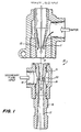
- Figure 1 is a partially cutaway, cross-sectional view of a preferred embodiment of a hydrokinetic amplifier having a secondary inlet according to the invention.
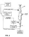
- Figure 2 is a schematic diagram of preferred ways of operating a hydrokinetic amplifier according to the invention.
- Figure 3 is a diagram of the performance of a hydrokinetic amplifier according to the invention compared with a prior art hydrokinetic amplifier.
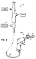
- FIG. 4 is a partially schematic view of a hydrokinetic amplifier provided with a secondary fluid inflow controlled by varying the fluid flow resistance of a load represented by a cleaning gun.
- a primary liquid input enters hydrokinetic amplifier 10 through a liquid input nozzle 11 to form a primary liquid jet directed into mixing chamber 12, which is partially cut away to shorten the view.
- Vapor that surrounds and accelerates the primary liquid jet enters hydrokinetic amplifier 10 via vapor nozzle 13 so that the vapor merges with the primary liquid jet and accelerates it through nozzle 15 and through minimum cross-sectional area 20, sometimes called "R area".
- the passageway through minimum cross-sectional area 20 can extend axially for a distance as illustrated or can be reduced axially to a single line within nozzle 15.
- passageway 15 terminates at end 14 to discharge and direct the primary liquid jet toward diffuser 16, having a diverging region 17 downstream of R area 20.
- Diffuser 16 also has a converging region 18 that surrounds and overlaps the terminated end 14 of passageway 15 and is spaced around passageway 15 to provide a secondary inlet.
- secondary inlet 18 be near the upstream end of diffuser 16 as illustrated and that passageway 15 terminate at end 14 before diverging from R area 20.
- Passageway 15 can also diverge from R area 20 before discharging into a secondary inlet located further downstream.
- the secondary inlet besides surrounding the primary liquid jet, can also be formed as a plurality of openings into passageway 15; and this can be especially effective if passageway 15 is diverging from R area 20.
- the secondary inflow rate is not limited by the size of R area 20 and does not affect the acceleration of the primary liquid jet through R area 20. Also, the temperature of the secondary fluid inflow does not affect the condensation of the primary motivating vapor, which occurs primarily above R area 20.
- converging region 18 When the secondary inflow is liquid, converging region 18 should be shaped so that the annular inflow region upstream of terminated end 14 converges for a nozzle effect accelerating the liquid inflow between the outside of passageway 15 and the inside of converging region 18. This speeds up the secondary liquid flow and aims it in the same direction as the primary jet so that the momentum of the secondary liquid is added to the momentum of the primary liquid jet. If the secondary inflow is a gas or vapor, then the annular inflow region between the outside of passageway 15 and the inside of conical region 18 should diverge or enlarge. This provides an expanding inflow region that accelerates a gas or vapor to combine its momentum with that of the primary liquid jet.
- the graph of FIG. 3 illustrates this.
- a prior art hydrokinetic amplifier having no secondary fluid inlet operates at a constant volume within range of pressures from points 30 to 31.
- the PV for a hydrokinetic amplifier 10 having secondary inlet 18 includes a variable volume up to a maximum possible flow at point 32 and pressures ranging slightly upward from point 31 to a peak 33, where a small inflow of secondary fluid occurs, and downward from peak 33 through a range of diminishing pressures and increasing flow rates.
- the PV of a combined flow is normally no greater than the PV of a primary flow, as evidenced in a jet pump, for example, but we have observed higher PV's for combined flows from hydrokinetic amplifier 10 than the PV of the primary flow through minimum cross-sectional area 20. Although we are not certain of the reason for this, it appears that admitting secondary flow to the upper region of diffuser 16 makes the diffuser more efficient than if the primary flow alone is flowing through the diffuser. Increased diffuser efficiency may arise from lack of vapor passing into the diffuser, lack of cavitation in the diffuser, and other factors; but the surprising increase in PV output when secondary liquid is merged with the primary is well substantiated in our work.
- One of the advantages of admitting a secondary liquid into inlet 18 is to allow hydrokinetic amplifier 10 to provide the maximum flow rate possible for a range of output pressure resistances. This makes amplifier 10 more versatile and more easily matched with output pressure resistances, which can also be varied during operation.
- amplifier 10 for powering a spray bar, for example, the total area of the openings of nozzles along the spray bar can be changed to vary the output pressure resistance; and throughout a range of such variation, amplifier 10 will provide a varying liquid flow rate up to maximum possible pressure. If the nozzle area is made larger, the delivery pressure reduces, but the flow rate increases. If the nozzle area is reduced, the delivery pressure increases, and the flow rate reduces.
- hydrokinetic amplifier 10 is more versatile and more like a centrifugal pump whose output pressure and volume can both vary.
- variable flow rate hydrokinetic amplifier can be installed to operate with whatever liquid and vapor pressures are available in an industrial environment and can use these to produce a maximum outflow to a load, which can vary in its fluid flow resistance. This allows considerable versatility in varying the load, which can receive the maximum fluid flow for any resistance, while the hydrokinetic amplifier efficiently combines its primary inputs and compensates for load resistance by automatically varying the flow rate of the secondary input.
- a secondary liquid can also vary the temperature of the output flow.
- the primary liquid input to a hydrokinetic amplifier must be cool enough relative to the motivating vapor to condense the vapor in the primary liquid jet and thereby transfer the vapor momentum to the liquid, but there is no limitation on the temperature of a secondary liquid combined with the primary liquid jet at secondary inlet 18.
- a secondary liquid inflow cooler than the primary liquid jet flowing through R area 20 can reduce and regulate the temperature of the combined outflow.
- a primary flow of 93,3°C (200°F) for example, can drive an outflow at 65,6°C (150°F), if desired, by combining a suitable proportion of a secondary liquid inflow at a lower temperature.
- the outflow temperature can be controlled, as shown schematically in FIG. 2, by sensing the temperature of the outflow from diffuser 16 and using that to control a valve in the secondary fluid inlet.
- the ability of the secondary inlet to accept different temperature liquids also allows it to accept secondary liquid or vapor hotter than the primary liquid jet. This can be used to recirculate hot washing water, for example, that could not be fed at high temperature into the primary liquid input. Cleaning chemicals, gases, and practically everything flowable can be directed into the secondary inlet to accommodate a wide variety of processes, such as evaporation, distillation, refrigeration, and others. Since a hydrokinetic amplifier can develop many times the output pressure of boiler vapor powering it, hydrokinetic amplifier 10 can be operated for feeding hot return water to a boiler via secondary inlet 18 while amplifier 10 is supplied with cool make-up water input to the primary inlet.
- hydrokinetic amplifier 10 allows control of proportional flow rates by varying the secondary inflow relative to the primary.
- the ability to increase the outflow rate by a large addition of secondary liquid allows amplifier 10 to pump cold water with only a minor increase in liquid output temperature.
- Vapor as the secondary fluid inflow also has several important uses, including evaporation and distillation processes.
- the motivating vapor accelerating the primary liquid jet through R area 20 can be evaporated from a material such as maple sap or tomato slurry, and the evaporation pressure can be subatmospheric.
- Secondary inlet 18 can be used to entrain more of the evaporated vapor into diffuser 16.
- the entrained vapor can be accelerated toward the diffuser in a diverging inlet 18, to add the vapor momentum to the liquid flow. This expands and cools the vapor somewhat, as the merged liquid and vapor proceed toward diverging region 17, where the velocity reduces and converts to pressure that condenses the vapor.
- the primary liquid input can be derived from the output of hydrokinetic amplifier 10, downstream of diffuser 16, as schematically shown in FIG. 2. If the secondary fluid input is liquid, it can cool the primary feedback liquid in a counter current heat exchanger as the feedback liquid heads for the primary inlet and the secondary liquid heads for secondary inlet 18. Since feeding back of pressurized output liquid to the primary liquid input speeds up the primary liquid jet and in turn increases the accelerated jet velocity and the output pressure, a feedback primary can give hydrokinetic amplifier 10 a very high pressure capability. This can increase the operating pressure range of amplifier 10 from very high pressures against very high output pressure resistances, down to much lower pressures and much higher flow rates augmented by a secondary liquid flow.
- Hydrokinetic amplifiers operated in a feedback mode have produced pressures as high as 20,7 MPA (3,000 psi), with no known upper limit, so that depending on the pressure strength of the piping and the maximum pressure resistance of the output, the operating range of amplifier 10 can be extended considerably by operating in the feedback mode as shown in FIG. 2.
- the sensing of outflow temperature and the control of secondary input can occur for secondary flows of either liquid or vapor and does not require the feedback mode that is also illustrated in FIG. 2. Also, feedback and single pass operation can be used with a variety of controls for different liquids and vapors to achieve a wide range of effects, all taking advantage of secondary input.
- a cleaning gun 25 having double barrels 26 and 27 and an operating trigger 28 can be connected by a line 29 to the output of hydrokinetic amplifier 10. This is supplied with a primary liquid and vapor in the usual way; and its secondary input is connected to a supply of an additive material 30, which can be a detergent or foaming agent, for example.
- a valve 31 in gun barrel 26 can be opened or closed by the operator to make gun 25 operate on either single barrel 27 or double barrels 26 and 27.
- gun 25 In the single-barreled mode, delivering an output only through barrel 27, gun 25 provides a high resistance load to the output of hydrokinetic amplifier 10; and this automatically shuts off any inflow of additive material 30 into the secondary input. The outflow through single barrel 27 is then hot washing water.
- gun 25 delivers a flow through both barrels 26 and 27 and, in this double-barreled mode, presents a low fluid flow resistance load to hydrokinetic amplifier 10. This automatically causes an inflow of additive material 30 into the secondary input.
- the primary and secondary flows have become merged and are delivered from both barrels 26 and 27 to apply a detergent or foaming agent, for example.
- the operator of gun 25 controls the flow of additive material, without involving any other moving parts.
- the outflow through both barrels 26 and 27 is at a lower pressure and higher flow rate than an outflow through single barrel 27. This can produce a flood of washing water and detergent, when valve 31 is open, and a vigorous, high-velocity rinse when valve 31 is closed.
- control of additive materials introduced to the outflow at the secondary input is not limited to washing guns and can be applied wherever a variable fluid flow resistance load is available for exerting the control. Since the secondary inflow automatically responds to varying load resistance, it can be turned on and off simply by changing the load.
Landscapes
- Engineering & Computer Science (AREA)
- Physics & Mathematics (AREA)
- Fluid Mechanics (AREA)
- Mechanical Engineering (AREA)
- General Engineering & Computer Science (AREA)
- Nozzles (AREA)
- Jet Pumps And Other Pumps (AREA)
Claims (20)
- Verfahren zum Zuführen einer Flüssigkeit an eine Zuladung durch einen hydrokinetischen Verstärker, enthaltend:
eine erste Flüssigkeitseinspeisung, die zu einem ersten Flüssigkeitsstrahl ausgebildet ist, der von einem Antriebsdampf umgeben ist, der die Bewegungsenergie des Dampfes an den ersten Flüssigkeitsstrahl überträgt und den ersten Flüssigkeitsstrahl durch einen minimalen Querschnittsbereich stromaufwärtig eines Diffusors, der hinter dem minimalen Quersschnittsbereich angeordnet ist, beschleunigt und mit einer Zuladung in Verbindung steht;
einen zweiten Eingang, um zuzulassen, daß sich eine zweite Flüssigkeit mit dem ersten Flüssigkeitsstrahl in einem Bereich hinter dem minimalen Querschnittsbereich vermischt, so daß sich die zweite Flüssigkeitsströmung und der erste Flüssigkeitsstrahl vermischen und weiter in den Diffusor strömen,
gekennzeichnet durch die folgenden Schritte:
Zulieferung der zweiten Flüssigkeit an den zweiten Eingang (18) derart, daß wenn sich der Flüssigkeitsströmungswiderstand der Zuladung verändert, die Strömungsrate des ersten Flüssigkeitsstrahls durch den minimalen Querschnittsbereich (20) konstant bleibt und sowohl die Einströmungsrate der zweiten Flüssigkeit als auch die Ausströmungsrate vom Diffusor (16) in umgekehrtem Verhätnis zu Änderungen des Flüssigkeitsströmungswiderstandes der Zuladung (25) variieren. - Verfahren nach Anspruch 1, bei dem beim Zuleiten der zweiten Flüssigkeit das Produkt aus Druck und Volumen der kombinierten ersten und zweiten Strömungen in dem Diffusor (16) das Produkt aus Druck und Volumen des ersten Flüssigkeitsstrahls durch den minimalen Querschnittsbereich (20) übersteigen.
- Verfahren nach Anspruch 1 oder 2, wobei die zweite Flüssigkeit ein Dampf ist, der den ersten Flüssigkeitsstrahl in den Diffusor (16) beschleunigt, wo Geschwindigkeit in Druck umgewandelt wird, und wobei ein Teil des Dampfes der zweiten Flüssigkeit in dem Diffusor (16) kondensiert.
- Verfahren nach einem der Ansprüche 1 bis 3, enthaltend den weiteren Schritt des Abziehens von Flüssigkeit für die erste Flüssigkeitseinspeisung stromabwärtig des Diffusors (16).
- Verfahren nach Anspruch 1 oder 2, enthaltend die weiteren Schritte des Abziehens von Flüssigkeit für die erste Flüssigkeitseinspeisung stromabwärtig des Diffusors (16) und Verwendung der zweiten Flüssigkeit, die an den zweiten Eingang (18) geliefert wird, zum Kühlen der ersten Flüssigkeitseinspeisung vor dem Vermischen der zweiten Flüssigkeit mit dem ersten Flüssigkeitsstrahl.
- Verfahren nach einem der Ansprüche 1 bis 5, enthaltend die Schritte des wahlweisen Steuern des Flüssigkeitsströmungswiderstandes der Zuladung (25).
- Verfahren nach Anspruch 6, wobei der Schritt des Erzeugens der Zulieferung der zweiten Flüssigkeit das Einrichten der zweiten Flüssigkeit beinhaltet, um ein Material (30) dem ersten Flüssigkeitsstrahl beizufügen, und wobei der wahlweise Steuerungsschritt (a) das Zuführen des Materials (30) an die Zuladung enthält durch Betreiben der Zuladung bei einem Strömungswiderstand, der niedrig genug ist, um eine zweite Flüssigkeit strömen zu lassen, und/oder (b) das Ausschließen des Materials (30) von der Zuladung durch das Betreiben der Zuladung bei einem strömungswiderstand, der hoch genug ist, um die zweite Flüssigkeitsströmung zu stoppen, wodurch der erste Flüssigkeitsstrahl nicht unterbrochen wird.
- Verfahren nach Anspruch 7, wobei die Zuladung eine doppelläufige Kanone (25) enthält und wobei der wahlweise Steuerungsschritt es zuläßt, daß die Flüssigkeitsströmung durch nur einen einzigen Lauf (27) der Kanone (25) stattfindet, um diesen hohen Flüssigkeitsströmungswiderstand zu erzielen und daß die Flüssigkeitsströmung durch beide Läufe (26, 27) der Kanone (25), den niedrigen Flüssigkeitsströmungswiderstand einrichtet.
- Verfahren nach einem der Ansprüche 1 bis 8, enthaltend die weiteren Schritte des Abtastens der Auslaßtemperatur von dem Diffusor (16), und das Steuern der zweiten Flüssigkeitsströmung in Reaktion auf die abgetastete Temperatur.
- Verfahren nach einem der Ansprüche 1, 2 und 4 bis 9, wobei die zweite Flüssigkeit eine höhere Temperatur hat als der erste Flüssigkeitsstrahl.
- Verfahren nach einem der Ansprüche 1 bis 10, enthaltend den weiteren Schritt des Variierens des Flüssigkeitsströmungswiderstandes der Ladung ohne die Einströmungsrate des Antriebsdampfes zu ändern.
- Verfahren nach einem der Ansprüche 1 bis 10, enthaltend den weiteren Schritt des Variierens des Flüssigkeitsströmungswiderstandes der Zuladung, ohne die Ströumgsrate der ersten Flüssigkeitseinspeisung zu ändern.
- System zum Liefern einer Flüssigkeit an eine Zuladung, wobei das System einen hydrokinetischen Verstärker enthält, der eine erste Flüssigkeitseinspeisung aufweist, die in einem ersten Flüssigkeitsstrahl ausgebildet ist, die von einem Antriebsdampf umgeben ist, der die Bewegungsenergie des Dampfes an den ersten Flüssigkeitsstrahl überträgt, und den ersten Flüssigkeitsstrahl durch einen minimalen Querschnittsbereich beschleunigt, und das einen Diffusor aufweist, der stromabwärtig des minimalen Querschnittsbereichs angeordnet ist und mit der Zuladung verbunden ist, gekennzeichnet duch einen zweiten Flüssigkeitseingang (18), der in dem hydrokinetischen Verstärker hinter dem minimalen Querschnittsbereich (20) und stromaufwärtig des Diffusors (16) angeordnet ist, um eine zweite Flüssigkeit mit dem ersten Flüssigkeitsstrahl in dem Diffusor (16) zu vermischen, und durch eine zweite Flüssigkeitszulieferung, die mit dem zweiten Flüssigkeitseingang (18) verbunden ist, wobei die zweite Zulieferung auf Änderungen des Widerstandes der Flüssigkeitsströmung des Diffusors (16) derart reagiert, daß wenn der Flüssigkeitsströmungswiderstand der Zuladung (25) sich ändert, die Flüssigkeitszulieferung an den zweiten Eingang (18) und die Ausspeisungsmenge vom Diffusor (16) an die Zuladung (25) sich umgekehrt mit dem Flüssigkeitsströmungswiderstand der Zuladung (25) ändert, und so daß die Einströmungsraten des ersten Flüssigkeitsstrahls und des Antriebsdampfes und die Einströmungsrate des ersten Flüssigkeitsstrahls durch den minimalen Querschnittsbereich (20) sich nicht zusmmen mit dem Zuladungswiderstand ändern.
- Flüssigkeitszuliefersystem nach Anspruch 13, wobei die erste Flüssigkeitseinspeisung stromabwärtig des Diffusors (16) abgezogen wird.
- Flüssigkeitszuliefersystem nach einem der Ansprüche 13 bis 14, enthaltend einen Wärmetauscher bei dem die erste Flüssigkeitseinspeisung durch die zweite Flüssigkeit auf dem Weg zum zweiten Flüssigkeitsausgang (18) abgekühlt wird.
- Flüssigkeitszuliefersystem nach einem der Ansprüche 13 bis 15, weiterhin enthaltend einen Mechanismus zum wahlweisen Steuern des Flüssigkeitsströmungswiderstandes der Zuladung (25).
- Flüssigkeitszuliefersystem nach Anspruch 16, wobei der Mechanismus zum wahlweisen Steuern des Flüssigkeitsströmungswiderstandes der Zuladung eine doppelläufige kanone (25) ist, wobei die Flüssigkeit durch beide Läufe der Kanone (26, 27) kann, um einen niedrigen Flüssigkeitsströmungswiderstand zu erzielen und wobei die Flüssigkeit auch durch nur einen Lauf (27) fließen kann, um einen hohen Flüssigkeitsströmungswiderstand zu erzielen.
- Flüssigkeitszuliefersystem nach einem der Ansprüche 13 bis 17, wobei die zweite Flüssigkeit einen Zusatzstoff (30) enthalt, wobei die Einspeisungsmenge des Zusatzstoffes (30) in den zweiten Flüssigkeitseingang (18) durch das Variieren des Flüssigkeitsströmungswiderstandes gesteuert wird.
- Flüssigkeitszuliefersystem nach einem der Ansprüche 13 bis 18, enthalten einen Sensor für die Temperatur der Ausspeisung aus dem Diffusor (16), und enthaltend ein Steuerventil, das auf den Sensor zum Steuern der Einspeisung in den zweiten Eingang (18) reagiert.
- Hydrokinetischer Verstärker, der in einem System nach Anspruch 13 bis 19 verwendet wird, der einen ersten Flüssigkeitseingang aufweist, der in dem ersten Flüssigkeitsstrahl ausgebildet ist, der von einem Antriebsdampf umgeben ist, der die Bewegungsenergie des Dampfes an den ersten Flüssigkeitsstrahl überträgt und den ersten Flüssigkeitsstrahl durch einen minimalen Querschnittsbereich stromaufwärtig eines Diffusors beschleunigt, der hinter dem minimalen Querschnittsbereich angeordnet ist, gekennzeichnet dadurch, daß(a) ein zweiter Flüssigkeitseingang zwischen dem minimalen Querschnittsbereich (20) und dem Diffusor (16) angeordnet ist, um eine zweite Flüssigkeit mit dem ersten Flüssigkeitsstrahl in dem Diffusor (16) zu vermischen,b) die erste Flüssigkeitseinspeisung stromabwärtig des Diffusors (16) abgezogen wird; undc) die zweite Flüssigkeit auf dem Weg zu dem zweiten Flüssigkeitseingang (18) zum Abkühlen der ersten Flüssigkeitseinspeisung angeordnet ist.
Applications Claiming Priority (4)
| Application Number | Priority Date | Filing Date | Title |
|---|---|---|---|
| US2458987A | 1987-03-11 | 1987-03-11 | |
| US24589 | 1987-03-11 | ||
| US07/151,821 US4781537A (en) | 1987-03-11 | 1988-02-03 | Variable flow rate system for hydrokinetic amplifier |
| US151821 | 1988-02-03 |
Publications (3)
| Publication Number | Publication Date |
|---|---|
| EP0282061A2 EP0282061A2 (de) | 1988-09-14 |
| EP0282061A3 EP0282061A3 (en) | 1988-11-17 |
| EP0282061B1 true EP0282061B1 (de) | 1992-09-16 |
Family
ID=26698624
Family Applications (1)
| Application Number | Title | Priority Date | Filing Date |
|---|---|---|---|
| EP88103822A Expired EP0282061B1 (de) | 1987-03-11 | 1988-03-10 | Veränderliches Durchflusssystem für hydrokinetische Verstärker |
Country Status (6)
| Country | Link |
|---|---|
| US (1) | US4781537A (de) |
| EP (1) | EP0282061B1 (de) |
| JP (1) | JPS63289300A (de) |
| CA (1) | CA1280640C (de) |
| DE (1) | DE3874570T2 (de) |
| ES (1) | ES2035129T3 (de) |
Cited By (3)
| Publication number | Priority date | Publication date | Assignee | Title |
|---|---|---|---|---|
| US8419378B2 (en) | 2004-07-29 | 2013-04-16 | Pursuit Dynamics Plc | Jet pump |
| US9004375B2 (en) | 2004-02-26 | 2015-04-14 | Tyco Fire & Security Gmbh | Method and apparatus for generating a mist |
| US9010663B2 (en) | 2004-02-26 | 2015-04-21 | Tyco Fire & Security Gmbh | Method and apparatus for generating a mist |
Families Citing this family (31)
| Publication number | Priority date | Publication date | Assignee | Title |
|---|---|---|---|---|
| US6616418B1 (en) * | 2002-03-01 | 2003-09-09 | Cne Mobile Scrubber Systems, Llc | Vapor evacuation device |
| DE69221935T2 (de) * | 1991-05-22 | 1998-04-09 | Toshiba Kawasaki Kk | Dampfinjektorsystem |
| US5586442A (en) * | 1994-10-17 | 1996-12-24 | Helios Research Corp. | Thermal absorption compression cycle |
| US5794447A (en) * | 1996-04-01 | 1998-08-18 | Helios Research Corporation | Rankine cycle boiler feed via hydrokinetic amplifier |
| JP3600384B2 (ja) * | 1996-09-12 | 2004-12-15 | 株式会社東芝 | 噴流加工装置、噴流加工システムおよび噴流加工方法 |
| RU2136977C1 (ru) * | 1998-03-24 | 1999-09-10 | Санкт-Петербургский государственный морской технический университет | Струйный насос |
| RU2155280C1 (ru) * | 1999-04-08 | 2000-08-27 | Фисенко Владимир Владимирович | Газожидкостной струйный аппарат |
| US6382321B1 (en) | 1999-09-14 | 2002-05-07 | Andrew Anderson Bates | Dewatering natural gas-assisted pump for natural and hydrocarbon wells |
| RU2198323C2 (ru) * | 2000-06-21 | 2003-02-10 | Куркулов Михаил Анатольевич | Способ непрерывной подачи пара в водяную магистраль и устройство для его осуществления |
| US20040052709A1 (en) * | 2002-03-01 | 2004-03-18 | Taylor Ernest L. | Vapor evacuation device |
| US6786700B2 (en) * | 2002-03-01 | 2004-09-07 | Ernest Taylor | Vapor evacuation device |
| ES2287521T3 (es) * | 2002-10-11 | 2007-12-16 | Pursuit Dynamics Plc. | Bomba de corcho. |
| US20080103217A1 (en) | 2006-10-31 | 2008-05-01 | Hari Babu Sunkara | Polyether ester elastomer composition |
| US20060242992A1 (en) * | 2005-05-02 | 2006-11-02 | Mark Nicodemus | Thermodynamic apparatus and methods |
| US20070036024A1 (en) * | 2005-08-10 | 2007-02-15 | Cleaning Systems, Inc. | Fluid blending and mixing system |
| US20070277501A1 (en) * | 2005-10-14 | 2007-12-06 | Sorenson Sidney D | Fluid dynamic power generator and methods |
| US8622608B2 (en) | 2006-08-23 | 2014-01-07 | M-I L.L.C. | Process for mixing wellbore fluids |
| GB0618196D0 (en) | 2006-09-15 | 2006-10-25 | Pursuit Dynamics Plc | An improved mist generating apparatus and method |
| RU2361166C1 (ru) * | 2008-01-09 | 2009-07-10 | Открытое акционерное общество "КуйбышевАзот" | Струйный водопаровой теплообменник |
| RU2387885C1 (ru) * | 2009-02-03 | 2010-04-27 | Виктор Сергеевич Бороздин | Парожидкостный струйный аппарат |
| US7784999B1 (en) * | 2009-07-01 | 2010-08-31 | Vortex Systems (International) Ci | Eductor apparatus with lobes for optimizing flow patterns |
| US8104745B1 (en) * | 2010-11-20 | 2012-01-31 | Vladimir Vladimirovich Fisenko | Heat-generating jet injection |
| JP5786765B2 (ja) * | 2012-03-07 | 2015-09-30 | 株式会社デンソー | エジェクタ |
| US8814531B2 (en) * | 2012-08-02 | 2014-08-26 | Briggs & Stratton Corporation | Pressure washers including jet pumps |
| US20150354403A1 (en) * | 2014-06-05 | 2015-12-10 | General Electric Company | Off-line wash systems and methods for a gas turbine engine |
| US9644643B2 (en) * | 2014-11-14 | 2017-05-09 | Hamilton Sundstrand Corporation | Aspirator pump with dual high pressure streams |
| WO2016090029A1 (en) | 2014-12-05 | 2016-06-09 | Briggs & Stratton Corporation | Pressure washers including jet pumps |
| CN106312837B (zh) * | 2016-09-22 | 2019-04-26 | 武汉大学 | 一种基于环形射流的后混式磨料水射流喷嘴 |
| KR101902542B1 (ko) * | 2016-12-29 | 2018-09-28 | 주식회사 현대케피코 | 연료증발가스 재순환장치용 이젝터 |
| DE102019202540A1 (de) * | 2019-02-25 | 2020-08-27 | Deutsches Institut Für Lebensmitteltechnik E.V. | Vorrichtung zur Erzeugung von Unterdruck |
| NO348446B1 (en) * | 2022-06-21 | 2025-01-27 | Norrde As | A multi-stage venturi-type apparatus, liquid treatment system, aquafarm, and method for treating liquid in a tank |
Family Cites Families (22)
| Publication number | Priority date | Publication date | Assignee | Title |
|---|---|---|---|---|
| US1026399A (en) * | 1910-01-19 | 1912-05-14 | Schutte & Koerting Company | Injector. |
| US1421844A (en) * | 1914-09-14 | 1922-07-04 | Westinghouse Electric & Mfg Co | Fluid-translating device |
| US1215321A (en) * | 1915-06-22 | 1917-02-06 | Expl Des Procedes Westinghouse Leblanc Sa | Ejector. |
| US1328139A (en) * | 1919-06-17 | 1920-01-13 | Jr William Saint Georg Elliott | Hydraulic water-forcing apparatus |
| CH101872A (fr) * | 1921-12-12 | 1923-11-01 | Eugene Caron Virgile | Procédé et appareil pour l'aspiration et la compression d'un fluide gazeux. |
| US1568466A (en) * | 1925-03-05 | 1926-01-05 | Superheater Co Ltd | Injector |
| US2107340A (en) * | 1934-10-09 | 1938-02-08 | Sellers William & Co Inc | Washer |
| US2207390A (en) * | 1939-07-31 | 1940-07-09 | John C White | Injector heater |
| DE855656C (de) * | 1941-04-13 | 1952-11-13 | Johann Hans Siebenhuener Heinl | Verfahren und Vorrichtung zum Foerdern von heissen Fluessigkeiten |
| US2397870A (en) * | 1943-02-24 | 1946-04-02 | Morgan Construction Co | Draft producing apparatus |
| FR972553A (fr) * | 1948-09-29 | 1951-01-31 | Procédé et appareil pour comprimer et chauffer une vapeur | |
| FR2161288A5 (de) * | 1971-11-19 | 1973-07-06 | Snecma | |
| SE366485B (de) * | 1972-09-08 | 1974-04-29 | Euroclean Ab | |
| CA1001193A (en) * | 1973-02-28 | 1976-12-07 | S.R.C. Laboratories | Variable flow nozzle |
| DE2337182A1 (de) * | 1973-07-21 | 1975-02-06 | Baelz Gmbh Helmut | Warmwasserheizungs- oder -bereitungsanlage |
| DE2410570C2 (de) * | 1974-03-06 | 1982-04-29 | Basf Ag, 6700 Ludwigshafen | Vorrichtung zum Ansaugen und Verdichten von Gasen und deren Vermischung mit Flüssigkeit |
| US3986523A (en) * | 1974-10-09 | 1976-10-19 | Partek Corporation Of Houston | High pressure fluid system |
| DE3005653A1 (de) * | 1980-02-15 | 1981-08-20 | Brown, Boveri & Cie Ag, 6800 Mannheim | Strahlpumpe |
| US4413785A (en) * | 1981-09-14 | 1983-11-08 | Carroll D. Engelbert | Variable pressure fluid cleaning wand |
| US4569635A (en) * | 1983-07-27 | 1986-02-11 | Helios Research Corp. | Hydrokinetic amplifier |
| US4673335A (en) * | 1984-05-21 | 1987-06-16 | Helios Research Corp. | Gas compression with hydrokinetic amplifier |
| FR2575678B1 (fr) * | 1985-01-04 | 1988-06-03 | Saint Gobain Vitrage | Ejecteur pneumatique de poudre |
-
1988
- 1988-02-03 US US07/151,821 patent/US4781537A/en not_active Expired - Lifetime
- 1988-03-10 DE DE8888103822T patent/DE3874570T2/de not_active Expired - Fee Related
- 1988-03-10 EP EP88103822A patent/EP0282061B1/de not_active Expired
- 1988-03-10 CA CA000561059A patent/CA1280640C/en not_active Expired - Lifetime
- 1988-03-10 ES ES198888103822T patent/ES2035129T3/es not_active Expired - Lifetime
- 1988-03-11 JP JP63058139A patent/JPS63289300A/ja active Pending
Cited By (4)
| Publication number | Priority date | Publication date | Assignee | Title |
|---|---|---|---|---|
| US9004375B2 (en) | 2004-02-26 | 2015-04-14 | Tyco Fire & Security Gmbh | Method and apparatus for generating a mist |
| US9010663B2 (en) | 2004-02-26 | 2015-04-21 | Tyco Fire & Security Gmbh | Method and apparatus for generating a mist |
| US8419378B2 (en) | 2004-07-29 | 2013-04-16 | Pursuit Dynamics Plc | Jet pump |
| US9239063B2 (en) | 2004-07-29 | 2016-01-19 | Pursuit Marine Drive Limited | Jet pump |
Also Published As
| Publication number | Publication date |
|---|---|
| ES2035129T3 (es) | 1993-04-16 |
| CA1280640C (en) | 1991-02-26 |
| EP0282061A2 (de) | 1988-09-14 |
| US4781537A (en) | 1988-11-01 |
| EP0282061A3 (en) | 1988-11-17 |
| DE3874570T2 (de) | 1993-04-08 |
| JPS63289300A (ja) | 1988-11-25 |
| DE3874570D1 (de) | 1992-10-22 |
Similar Documents
| Publication | Publication Date | Title |
|---|---|---|
| US4781537A (en) | Variable flow rate system for hydrokinetic amplifier | |
| US4951713A (en) | Overflow check system having automatic start-up | |
| US4321801A (en) | Jet operated heat pump | |
| EP0704661B1 (de) | Abgabevorrichtung mit Unterkühler für Kryoflüssigkeit | |
| JP2006508294A (ja) | 原動機或いは作業機械の流入路への液体噴射を制御する方法 | |
| JPH04506554A (ja) | 状態調節弁 | |
| US4569635A (en) | Hydrokinetic amplifier | |
| US1137767A (en) | Ejector. | |
| NO171423B (no) | Pumpeanordning | |
| US4687138A (en) | Device in or for high-pressure cleaning units for heating the water by circulation | |
| JPH0672554B2 (ja) | 連続流燃料循環装置 | |
| JPH01196000A (ja) | 原子炉の非常時炉心冷却系 | |
| US5442921A (en) | Targeted fluid delivery system | |
| US3976391A (en) | Rotodynamic fluid pumps | |
| EP0273677A3 (de) | Durchflusssteuergerät und Hochdruck-Flüssigkeitssystem mit einem solchen Gerät | |
| US4637760A (en) | Apparatus for transporting articles by fluid flow through a pipe system | |
| RU2072454C1 (ru) | Жидкостно-газовый эжектор | |
| GB2225612A (en) | Improvements in liquid jet-producing apparatus | |
| NL193280C (nl) | Inrichting voor het bereiden van met CO2 geïmpregneerd water, bestemd voor het begieten van planten. | |
| CA2250514A1 (en) | Rankine cycle boiler feed via hydrokinetic amplifier | |
| WO2004057196A1 (en) | A pumping system | |
| US3498307A (en) | Flow control apparatus | |
| US6767192B2 (en) | Vapor jet pump with ejector stage in foreline | |
| US2530638A (en) | Liquid heater control | |
| JPH01260204A (ja) | 復水回収ポンプ |
Legal Events
| Date | Code | Title | Description |
|---|---|---|---|
| PUAI | Public reference made under article 153(3) epc to a published international application that has entered the european phase |
Free format text: ORIGINAL CODE: 0009012 |
|
| AK | Designated contracting states |
Kind code of ref document: A2 Designated state(s): BE DE ES FR GB IT SE |
|
| PUAL | Search report despatched |
Free format text: ORIGINAL CODE: 0009013 |
|
| AK | Designated contracting states |
Kind code of ref document: A3 Designated state(s): BE DE ES FR GB IT SE |
|
| 17P | Request for examination filed |
Effective date: 19890510 |
|
| 17Q | First examination report despatched |
Effective date: 19900309 |
|
| GRAA | (expected) grant |
Free format text: ORIGINAL CODE: 0009210 |
|
| AK | Designated contracting states |
Kind code of ref document: B1 Designated state(s): BE DE ES FR GB IT SE |
|
| REF | Corresponds to: |
Ref document number: 3874570 Country of ref document: DE Date of ref document: 19921022 |
|
| ITF | It: translation for a ep patent filed | ||
| ET | Fr: translation filed | ||
| ITTA | It: last paid annual fee | ||
| REG | Reference to a national code |
Ref country code: ES Ref legal event code: FG2A Ref document number: 2035129 Country of ref document: ES Kind code of ref document: T3 |
|
| PLBE | No opposition filed within time limit |
Free format text: ORIGINAL CODE: 0009261 |
|
| STAA | Information on the status of an ep patent application or granted ep patent |
Free format text: STATUS: NO OPPOSITION FILED WITHIN TIME LIMIT |
|
| 26N | No opposition filed | ||
| EAL | Se: european patent in force in sweden |
Ref document number: 88103822.8 |
|
| PGFP | Annual fee paid to national office [announced via postgrant information from national office to epo] |
Ref country code: SE Payment date: 20000222 Year of fee payment: 13 |
|
| PGFP | Annual fee paid to national office [announced via postgrant information from national office to epo] |
Ref country code: ES Payment date: 20000314 Year of fee payment: 13 |
|
| PGFP | Annual fee paid to national office [announced via postgrant information from national office to epo] |
Ref country code: BE Payment date: 20000317 Year of fee payment: 13 |
|
| PGFP | Annual fee paid to national office [announced via postgrant information from national office to epo] |
Ref country code: FR Payment date: 20010219 Year of fee payment: 14 |
|
| PGFP | Annual fee paid to national office [announced via postgrant information from national office to epo] |
Ref country code: DE Payment date: 20010220 Year of fee payment: 14 |
|
| PGFP | Annual fee paid to national office [announced via postgrant information from national office to epo] |
Ref country code: GB Payment date: 20010221 Year of fee payment: 14 |
|
| PG25 | Lapsed in a contracting state [announced via postgrant information from national office to epo] |
Ref country code: SE Free format text: LAPSE BECAUSE OF NON-PAYMENT OF DUE FEES Effective date: 20010311 |
|
| PG25 | Lapsed in a contracting state [announced via postgrant information from national office to epo] |
Ref country code: ES Free format text: LAPSE BECAUSE OF NON-PAYMENT OF DUE FEES Effective date: 20010312 |
|
| PG25 | Lapsed in a contracting state [announced via postgrant information from national office to epo] |
Ref country code: BE Free format text: LAPSE BECAUSE OF NON-PAYMENT OF DUE FEES Effective date: 20010331 |
|
| BERE | Be: lapsed |
Owner name: HELIOS RESEARCH CORP. Effective date: 20010331 |
|
| EUG | Se: european patent has lapsed |
Ref document number: 88103822.8 |
|
| REG | Reference to a national code |
Ref country code: GB Ref legal event code: IF02 |
|
| PG25 | Lapsed in a contracting state [announced via postgrant information from national office to epo] |
Ref country code: GB Free format text: LAPSE BECAUSE OF NON-PAYMENT OF DUE FEES Effective date: 20020310 |
|
| PG25 | Lapsed in a contracting state [announced via postgrant information from national office to epo] |
Ref country code: DE Free format text: LAPSE BECAUSE OF NON-PAYMENT OF DUE FEES Effective date: 20021001 |
|
| GBPC | Gb: european patent ceased through non-payment of renewal fee |
Effective date: 20020310 |
|
| PG25 | Lapsed in a contracting state [announced via postgrant information from national office to epo] |
Ref country code: FR Free format text: LAPSE BECAUSE OF NON-PAYMENT OF DUE FEES Effective date: 20021129 |
|
| REG | Reference to a national code |
Ref country code: FR Ref legal event code: ST |
|
| REG | Reference to a national code |
Ref country code: ES Ref legal event code: FD2A Effective date: 20030203 |
|
| PG25 | Lapsed in a contracting state [announced via postgrant information from national office to epo] |
Ref country code: IT Free format text: LAPSE BECAUSE OF NON-PAYMENT OF DUE FEES Effective date: 20050310 |