EP0282293A2 - Ferritloser, nicht-reziproker Phasenschieber und Zirkulator - Google Patents
Ferritloser, nicht-reziproker Phasenschieber und Zirkulator Download PDFInfo
- Publication number
- EP0282293A2 EP0282293A2 EP88302070A EP88302070A EP0282293A2 EP 0282293 A2 EP0282293 A2 EP 0282293A2 EP 88302070 A EP88302070 A EP 88302070A EP 88302070 A EP88302070 A EP 88302070A EP 0282293 A2 EP0282293 A2 EP 0282293A2
- Authority
- EP
- European Patent Office
- Prior art keywords
- phase shift
- phase
- terminals
- phase shifter
- terminal
- Prior art date
- Legal status (The legal status is an assumption and is not a legal conclusion. Google has not performed a legal analysis and makes no representation as to the accuracy of the status listed.)
- Granted
Links
Images


Classifications
-
- H—ELECTRICITY
- H03—ELECTRONIC CIRCUITRY
- H03H—IMPEDANCE NETWORKS, e.g. RESONANT CIRCUITS; RESONATORS
- H03H7/00—Multiple-port networks comprising only passive electrical elements as network components
- H03H7/18—Networks for phase shifting
- H03H7/185—Networks for phase shifting comprising distributed impedance elements together with lumped impedance elements
-
- H—ELECTRICITY
- H01—ELECTRIC ELEMENTS
- H01P—WAVEGUIDES; RESONATORS, LINES, OR OTHER DEVICES OF THE WAVEGUIDE TYPE
- H01P1/00—Auxiliary devices
- H01P1/18—Phase-shifters
-
- H—ELECTRICITY
- H01—ELECTRIC ELEMENTS
- H01P—WAVEGUIDES; RESONATORS, LINES, OR OTHER DEVICES OF THE WAVEGUIDE TYPE
- H01P1/00—Auxiliary devices
- H01P1/32—Non-reciprocal transmission devices
- H01P1/38—Circulators
- H01P1/397—Circulators using non- reciprocal phase shifters
-
- H—ELECTRICITY
- H03—ELECTRONIC CIRCUITRY
- H03H—IMPEDANCE NETWORKS, e.g. RESONANT CIRCUITS; RESONATORS
- H03H7/00—Multiple-port networks comprising only passive electrical elements as network components
- H03H7/52—One-way transmission networks, i.e. unilines
Definitions
- This invention relates to an improved circulator, and more particularly to a non-ferrite, non-reciprocal phase shifter capable of monolithic construction.
- Such a four-port device is typically even bigger and more expensive than the three-port variety: it includes a combination of directional couplers and/or magic-Tees with two non-reciprocal phase shifting transmission lines between them.
- One shortcoming of both the three- and four-port circulators is that they must be sized corresponding to the wavelength of the energy so that circulators typically are not made for use below the microwave range. Typical sizes range from one half inch to two or three inches in diameter, which precludes integral monolithic fabrication with associated circuitry.
- present ferrite circulators require permanent magnet bias and non-magnetic housings.
- the invention results from the realization that a non-ferrite circulator of extremely small size and capable of monolithic fabrication can be effected using phase shifters made with a bidirectional transmission medium and an amplifier which introduces one phase shift in one direction and a larger phase shift in the other direction.
- This invention features a bidirectional phase shifter including a transmission connected between first and second terminals and having a predetermined phase shift which is the same in each direction.
- An amplifier circuit is connected between the first and second terminals for introducing its inherent phase shift in one direction and causing a phase shift in excess of its inherent phase shift in the other direction for establishing a non-reciprocal phase shift.
- the amplifier circuit includes an amplifier and coupling means for interconnecting the amplifier with the first and second terminals.
- the coupling means may be capacitors and the amplifier may be a transistor with one electrode grounded and the other two electrodes connected one to each of the first and second terminals.
- the amplifier circuit may have three ports, one connected to the first terminal, one connected to the second terminal, and one connected to a third terminal intermediate the first and second terminals.
- the transmission medium introduces approximately a 90° phase shift and the amplifier circuit introduces an inherent phase shift of approximately 180°.
- the invention also features a circulator such as a three-port circulator made by combining such phase shifters.
- a circulator such as a three-port circulator made by combining such phase shifters.
- Three such bidirectional phase shifters may be combined in a ring so that the first terminal of each shifter is interconnected with the second terminal of another.
- the first terminal of each phase shifter is interconnected with the second terminal of another phase shifter through at least one impedance matching element.
- the invention also features a four-port circulator having at least one non-reciprocal bi-directional phase shifter, and a second bi-directional phase shifter which may be non-reciprocal or reciprocal.
- a passive four-port coupling network which couples the two bi-directional phase shifters.
- One or both of the couplers may be magic T couplers or one or both of the couplers may be directional couplers, or one coupler may be a magic T coupler while the other is a directional coupler.
- the bidirectional phase shifter embodying this invention may be accomplished using a transmission medium connected between first and second terminals having a predetermined phase shift which is the same in each direction.
- a transmission medium may include a conventional transmission line, or a lumped element transmission line, or a loaded transmission line, or any other wave transmission medium in which the propagating wave sees a phase shift.
- the amplifier circuit may include an amplifier of unity gain or less or a simple transistor, so long as it is an active circuit element and passes current in one direction only.
- the amplifier circuit may also include coupling means such as capacitors for interconnecting the amplifier with the first and second terminals. If the amplifier is simply a transistor it may be arranged with one electrode grounded and the other two electrodes connected one to each of the first and second terminals. Or the transmision medium may be in two parts with an intermediate terminal between them and the amplifier or transistor may have three ports or electrodes, one connected to each of the first and second terminals with the third electrode connected to a third terminal intermediate the first and second.
- the transmission medium may introduce approximately a 90° phase shift while the amplifier circuit introduces an inherent phase shift of approximately 180° in the forward direction, while in the reverse direction it introduces a phase shift of 270° because wave propagation cannot occur in the reverse direction.
- Impedance circuits may be provided with each of the terminals to provide, for example, a typical 50 ohm matching impedance.
- phase shifters may be connected together end to end in a ring to produce a typical three-port circulator, and impedance circuits may be used to provide impedance matching with the associated circuitry.
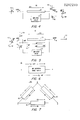
- phase shifter 10 which includes a transmission medium 12 interconnected between the first terminal 14 and the second terminal 16. Also connected between those terminals is an amplifier circuit 18 which may include amplifier circuit 20 and coupling circuits 22 and 24. In some embodiments, amplifier 20 may have a third port interconnected with an intermediate terminal indicated in Fig. 1 by phantom line 26.
- An impedance circuit 28 may be connected between first terminal 14 and input terminal 32, and impedance circuit 30 may be interconnected betwen second terminal 16 and output terminal 34, for purposes of impedance matching.
- phase shifter 10a may include a conventional transmission line 12a coupled to an amplifier circuit 18a which includes coupling capacitors 22a and 24a and a transistor 20a.
- the control electrode 40 of transistor 20a is connected to terminal 14a through capacitor 22a.
- One of the load electrodes 42 is connected through capacitor 24a to second terminal 16a.
- the other load electrode 44 is connected to ground 46.
- phase shifter 10b includes a transmission line having two sections 12b and 12bb with an intermediate terminal 50 between them.
- amplifier 18b includes a transistor 20b whose control electrode 40b is connected through capacitor 22b to first terminal 14b.
- One load electrode 42b is connected to terminal 50 through capacitor 24b while the other load electrode 44b is connected not to ground but to second terminal 16b through capacitor 25.
- the amplifier may have the simplest implementation; it may have a gain of unity or less; it may perform other functions.
- phase shifter according to this invention is shown schematically with the forward direction indicated by arrow 60. It is assumed for purposes of this explanation that transmission medium 12 has a phase shift of -90° while the amplifier circuit 18 has an inherent phase shift of -180°.
- a signal input at first terminal 14 has a phase of 0° as indicated by phase diagram 62.
- phase diagram 64 After passing through transmission medium 12, that same signal arrives at the output at second terminal 16 having a phase of -90° as indicated by phase diagram 64.
- the signal moves through amplifier 18 and arrives at the output at terminal 16 having a phase of -180° as indicated by phase diagram 66.
- the input signal at terminal 16 has a phase of 0° as indicated in phase diagram 72.
- the signal passes through medium 12 and arrives at terminal 14, it has a phase of -90° as indicated in phase diagram 74.
- a portion of the same signal unable to enter amplifier circuit 18 in the reverse direction, also moves through transmission medium 12 where it picks up a -90° phase shift. This can be seen by following the spiral arrow 76.
- the signal then passes through amplifier 18, where it picks up an additional -180° phase shift for a total of -270°.
- phase shifter 10 of this invention provides a phase forward P f phase shift of -120° and a phase reverse P r of -60°.
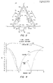
- phase shifters When such phase shifters are connected together in the form of a three-port circulator 100, Fig. 7, it can be seen that they provide the isolation function characteristic of circulators.
- phase shift P12 moves from circulator port 1 in Fig. 7 to circulator port 2 in the forward direction, phase shift P12 is equal to -120°.
- the other path between circulator ports 1 and 2, path 132, produces a phase shift P132 of -120°.
- the phase shift along path 13, P13 is -60°.
- the phase shift P123 along the other path to port 3 is -240°, so the signals are out of phase at port 3. They cancel, and so port 3 is isolated.
- the first terminal 14a of each phase shifter 10a may be connected directly to the second terminal 16a of the adjacent phase shifter 10a as indicated by dashed lines 90, 92 and 94.
- the preferred construction in Fig. 8 includes impedance circuits 112, 114; 116, 118; and 120, 122, for the purposes of matching the impedance so that it appears the same at each of the ports 1, 2 and 3.
- Fig. 9 The practicality of the circulator according to this invention can be seen with respect to the calculated performance of an X-band circulator according to this invention shown in Fig. 9.
- insertion loss, line 120, from port 1 to port 2 is barely 1 DB down in the area of interest, namely 9 GHz.
- the return loss 122 for reflections from port 2 back to port 1 is down over 29 DBs, while the isolation 124 between ports 1 and 3 is off scale, well below 30 DB down.
- a four-port circulator 150 can be made having four ports 1, 2, 3 and 4, Fig. 10A, which provides a phase shift in one direction of ⁇ r and in the opposite direction of ⁇ r + ⁇ by using a non-reciprocal bi-directional phase shifter 10b in conjunction with a reciprocal phase shifter 152.
- Ports 1 and 2 are in the "magic-T” configuration and ports 3 and 4 are also in the "magic-T” configuration.
- Reciprocal phase shifter 152 provides the same phase shift, l r , in both directions.
- the non-reciprocal phase shifter produces a phase shift of ⁇ r in one direction and l r + ⁇ in the other direction.
- reciprocal phase shifter 152 and non-reciprocal phase shifter 10b can be combined in a four-port circulator 154, Fig. 10B, in which the four ports are connected as two directional couplers 1, 2 and 3, 4.
- four-port circulator 156 is constructed with ports 1 and 2 as a directional coupler and ports 3 and 4 as a "magic-T" connection.
Landscapes
- Networks Using Active Elements (AREA)
Applications Claiming Priority (2)
| Application Number | Priority Date | Filing Date | Title |
|---|---|---|---|
| US07/025,594 US4801901A (en) | 1987-03-13 | 1987-03-13 | Non-ferrite non-reciprocal phase shifter and circulator |
| US25594 | 1987-03-13 |
Publications (3)
| Publication Number | Publication Date |
|---|---|
| EP0282293A2 true EP0282293A2 (de) | 1988-09-14 |
| EP0282293A3 EP0282293A3 (en) | 1990-01-24 |
| EP0282293B1 EP0282293B1 (de) | 1993-08-25 |
Family
ID=21826964
Family Applications (1)
| Application Number | Title | Priority Date | Filing Date |
|---|---|---|---|
| EP88302070A Expired - Lifetime EP0282293B1 (de) | 1987-03-13 | 1988-03-10 | Ferritloser, nicht-reziproker Phasenschieber und Zirkulator |
Country Status (4)
| Country | Link |
|---|---|
| US (1) | US4801901A (de) |
| EP (1) | EP0282293B1 (de) |
| JP (1) | JP2583561B2 (de) |
| DE (1) | DE3883404T2 (de) |
Cited By (11)
| Publication number | Priority date | Publication date | Assignee | Title |
|---|---|---|---|---|
| EP0387949A1 (de) * | 1989-03-14 | 1990-09-19 | Laboratoires D'electronique Philips | Integrierte Halbleitervorrichtung mit einer aktiven Isolatorschaltung |
| WO2005008832A3 (en) * | 2003-07-14 | 2005-03-24 | Photonicsystems Inc | Bi-directional signal interface |
| US7809216B2 (en) | 2007-03-16 | 2010-10-05 | Photonic Systems, Inc. | Bi-directional signal interface and apparatus using same |
| US8433163B2 (en) | 2008-04-21 | 2013-04-30 | Photonic Systems, Inc | Bi-directional signal interface with enhanced isolation |
| US8755750B2 (en) | 2010-05-22 | 2014-06-17 | Photonic Systems, Inc. | Wide-bandwidth signal canceller |
| US9209840B2 (en) | 2012-07-30 | 2015-12-08 | Photonic Systems, Inc. | Same-aperture any-frequency simultaneous transmit and receive communication system |
| US9935680B2 (en) | 2012-07-30 | 2018-04-03 | Photonic Systems, Inc. | Same-aperture any-frequency simultaneous transmit and receive communication system |
| US10158432B2 (en) | 2015-10-22 | 2018-12-18 | Photonic Systems, Inc. | RF signal separation and suppression system and method |
| US10374656B2 (en) | 2012-07-30 | 2019-08-06 | Photonic Systems, Inc. | Same-aperture any-frequency simultaneous transmit and receive communication system |
| US10623986B2 (en) | 2015-10-22 | 2020-04-14 | Photonic Systems, Inc. | RF signal separation and suppression system and method |
| US11539392B2 (en) | 2012-07-30 | 2022-12-27 | Photonic Systems, Inc. | Same-aperture any-frequency simultaneous transmit and receive communication system |
Families Citing this family (10)
| Publication number | Priority date | Publication date | Assignee | Title |
|---|---|---|---|---|
| US4908820A (en) * | 1989-03-29 | 1990-03-13 | Hittite Microwave Corporation | Non-reciprocal bidirectional duplexer |
| US5608361A (en) * | 1995-05-15 | 1997-03-04 | Massachusetts Institute Of Technology | Advanced ring-network circulator |
| US20060183437A1 (en) * | 2003-03-21 | 2006-08-17 | Koninklijke Philips Electronics N.V. | Circuit arrangement for a mobile radio device |
| US7541890B2 (en) * | 2007-10-29 | 2009-06-02 | Applied Radar, Inc. | Quasi active MIMIC circulator |
| US9577683B2 (en) | 2013-04-22 | 2017-02-21 | University Of Washington Through Its Center For Commercialization | Systems, transceivers, receivers, and methods including cancellation circuits having multiport transformers |
| CN107078722B (zh) * | 2014-11-26 | 2020-05-12 | 美国休斯研究所 | 具有射频扼流圈的有源环流器 |
| WO2019195881A1 (en) * | 2018-04-09 | 2019-10-17 | The University Of Queensland | Improved microwave circulator |
| US10868576B2 (en) | 2018-04-27 | 2020-12-15 | Board Of Trustees Of The University Of Illinois | Frequency independence for synthesis within programmable non-reciprocal network circuit |
| WO2021254586A1 (en) * | 2020-06-15 | 2021-12-23 | Huawei Technologies Co., Ltd. | Quadrature quasi-circulator |
| US12451575B2 (en) * | 2022-08-22 | 2025-10-21 | Navjot Kaur KHAIRA | Magnetless cryogenic circulator |
Family Cites Families (11)
| Publication number | Priority date | Publication date | Assignee | Title |
|---|---|---|---|---|
| US2866949A (en) * | 1953-10-29 | 1958-12-30 | Bell Telephone Labor Inc | Microwave circulators, isolators, and branching filters |
| US3544999A (en) * | 1960-05-04 | 1970-12-01 | Raytheon Co | Coupling circuits for scanning antennas and the like |
| NL284344A (de) * | 1961-11-22 | |||
| US3581122A (en) * | 1967-10-26 | 1971-05-25 | Bell Telephone Labor Inc | All-pass filter circuit having negative resistance shunting resonant circuit |
| US3667065A (en) * | 1970-09-04 | 1972-05-30 | Bell Telephone Labor Inc | Feed-forward amplifier having arbitrary gain-frequency characteristic |
| US3668563A (en) * | 1970-12-21 | 1972-06-06 | Rca Corp | Broadband circulator wherein differential phase shift varies with frequency in predetermined manner |
| US3700832A (en) * | 1971-08-19 | 1972-10-24 | Bell Telephone Labor Inc | N-port circulator |
| FR2212653B1 (de) * | 1973-01-02 | 1977-04-22 | Lignes Telegraph Telephon | |
| JPS50100443U (de) * | 1974-01-22 | 1975-08-20 | ||
| US4266204A (en) * | 1979-09-04 | 1981-05-05 | Sperry Rand Corporation | Delay line signal equalizer for magnetic recording signal detection circuits |
| JPH115044A (ja) * | 1997-06-16 | 1999-01-12 | Yanmar Sangyo Kk | 複合シャワー水栓 |
-
1987
- 1987-03-13 US US07/025,594 patent/US4801901A/en not_active Expired - Lifetime
-
1988
- 1988-03-10 EP EP88302070A patent/EP0282293B1/de not_active Expired - Lifetime
- 1988-03-10 DE DE88302070T patent/DE3883404T2/de not_active Expired - Fee Related
- 1988-03-13 JP JP63059204A patent/JP2583561B2/ja not_active Expired - Lifetime
Cited By (19)
| Publication number | Priority date | Publication date | Assignee | Title |
|---|---|---|---|---|
| FR2644653A1 (fr) * | 1989-03-14 | 1990-09-21 | Labo Electronique Physique | Dispositif semiconducteur integre incluant un circuit isolateur actif |
| EP0387949A1 (de) * | 1989-03-14 | 1990-09-19 | Laboratoires D'electronique Philips | Integrierte Halbleitervorrichtung mit einer aktiven Isolatorschaltung |
| US8868006B2 (en) | 2003-07-14 | 2014-10-21 | Photonic Systems, Inc. | Bi-directional signal interface |
| WO2005008832A3 (en) * | 2003-07-14 | 2005-03-24 | Photonicsystems Inc | Bi-directional signal interface |
| US7555219B2 (en) | 2003-07-14 | 2009-06-30 | Photonic Systems, Inc. | Bi-directional signal interface |
| US7826751B2 (en) | 2003-07-14 | 2010-11-02 | Photonic Systems, Inc. | Bi-directional signal interface |
| US7809216B2 (en) | 2007-03-16 | 2010-10-05 | Photonic Systems, Inc. | Bi-directional signal interface and apparatus using same |
| US8433163B2 (en) | 2008-04-21 | 2013-04-30 | Photonic Systems, Inc | Bi-directional signal interface with enhanced isolation |
| US8755750B2 (en) | 2010-05-22 | 2014-06-17 | Photonic Systems, Inc. | Wide-bandwidth signal canceller |
| US9209840B2 (en) | 2012-07-30 | 2015-12-08 | Photonic Systems, Inc. | Same-aperture any-frequency simultaneous transmit and receive communication system |
| US9935680B2 (en) | 2012-07-30 | 2018-04-03 | Photonic Systems, Inc. | Same-aperture any-frequency simultaneous transmit and receive communication system |
| US10374656B2 (en) | 2012-07-30 | 2019-08-06 | Photonic Systems, Inc. | Same-aperture any-frequency simultaneous transmit and receive communication system |
| US10425121B2 (en) | 2012-07-30 | 2019-09-24 | Photonic Systems, Inc. | Same-aperture any-frequency simultaneous transmit and receive communication system |
| US10651886B2 (en) | 2012-07-30 | 2020-05-12 | Photonic Systems, Inc. | Same-aperture any-frequency simultaneous transmit and receive communication system |
| US10879950B2 (en) | 2012-07-30 | 2020-12-29 | Photonic Systems, Inc. | Same-aperture any-frequency simultaneous transmit and receive communication system |
| US11539392B2 (en) | 2012-07-30 | 2022-12-27 | Photonic Systems, Inc. | Same-aperture any-frequency simultaneous transmit and receive communication system |
| US10158432B2 (en) | 2015-10-22 | 2018-12-18 | Photonic Systems, Inc. | RF signal separation and suppression system and method |
| US10623986B2 (en) | 2015-10-22 | 2020-04-14 | Photonic Systems, Inc. | RF signal separation and suppression system and method |
| US11817989B2 (en) | 2015-10-22 | 2023-11-14 | Photonic Systems, Inc. | RF signal separation and suppression system and method |
Also Published As
| Publication number | Publication date |
|---|---|
| US4801901A (en) | 1989-01-31 |
| JPS63290402A (ja) | 1988-11-28 |
| EP0282293A3 (en) | 1990-01-24 |
| EP0282293B1 (de) | 1993-08-25 |
| DE3883404D1 (de) | 1993-09-30 |
| JP2583561B2 (ja) | 1997-02-19 |
| DE3883404T2 (de) | 1994-02-24 |
Similar Documents
| Publication | Publication Date | Title |
|---|---|---|
| EP0282293B1 (de) | Ferritloser, nicht-reziproker Phasenschieber und Zirkulator | |
| Tanaka et al. | Slot-coupled directional couplers between double-sided substrate microstrip lines and their applications | |
| US3560893A (en) | Surface strip transmission line and microwave devices using same | |
| US2999988A (en) | Resonant directional couplers | |
| US4902992A (en) | Millimeter-wave multiplexers | |
| US2866949A (en) | Microwave circulators, isolators, and branching filters | |
| US5825260A (en) | Directional coupler for the high-frequency range | |
| US3484724A (en) | Transmission line quadrature coupler | |
| US6639490B2 (en) | Ninety degree coupler for radio frequency degraded circuits | |
| US6201453B1 (en) | H-plane hermetic sealed waveguide probe | |
| US6078227A (en) | Dual quadrature branchline in-phase power combiner and power splitter | |
| US4309666A (en) | Semiconductor amplifier | |
| US10211502B2 (en) | Wide band radio frequency circulator | |
| US4823096A (en) | Variable ratio power divider/combiner | |
| JPS61214625A (ja) | アンテナ結合回路 | |
| KR20000062617A (ko) | 유전체 필터, 유전체 듀플렉서, 및 통신 장치 | |
| US4207547A (en) | Reflection mode notch filter | |
| US3477028A (en) | Balanced signal mixers and power dividing circuits | |
| US3525952A (en) | Duplexer having two non-reciprocal phase shifting means | |
| US3562651A (en) | Microwave hybrid junction circuit and frequency translators constructed therefrom | |
| JP2003087014A (ja) | 非可逆回路素子および通信装置 | |
| US3886499A (en) | High frequency electrical network with frequency dependent characteristics having a constant input resistance | |
| JPH07283615A (ja) | 非可逆回路装置 | |
| JPH0993004A (ja) | 非可逆回路素子 | |
| US5585769A (en) | Passive temperature variable phase-shifter |
Legal Events
| Date | Code | Title | Description |
|---|---|---|---|
| PUAI | Public reference made under article 153(3) epc to a published international application that has entered the european phase |
Free format text: ORIGINAL CODE: 0009012 |
|
| AK | Designated contracting states |
Kind code of ref document: A2 Designated state(s): DE FR GB IT |
|
| PUAL | Search report despatched |
Free format text: ORIGINAL CODE: 0009013 |
|
| AK | Designated contracting states |
Kind code of ref document: A3 Designated state(s): DE FR GB IT |
|
| 17P | Request for examination filed |
Effective date: 19900614 |
|
| 17Q | First examination report despatched |
Effective date: 19921002 |
|
| GRAA | (expected) grant |
Free format text: ORIGINAL CODE: 0009210 |
|
| AK | Designated contracting states |
Kind code of ref document: B1 Designated state(s): DE FR GB IT |
|
| ITF | It: translation for a ep patent filed | ||
| REF | Corresponds to: |
Ref document number: 3883404 Country of ref document: DE Date of ref document: 19930930 |
|
| ET | Fr: translation filed | ||
| PGFP | Annual fee paid to national office [announced via postgrant information from national office to epo] |
Ref country code: GB Payment date: 19940309 Year of fee payment: 7 |
|
| PGFP | Annual fee paid to national office [announced via postgrant information from national office to epo] |
Ref country code: FR Payment date: 19940317 Year of fee payment: 7 |
|
| PLBE | No opposition filed within time limit |
Free format text: ORIGINAL CODE: 0009261 |
|
| STAA | Information on the status of an ep patent application or granted ep patent |
Free format text: STATUS: NO OPPOSITION FILED WITHIN TIME LIMIT |
|
| 26N | No opposition filed | ||
| PG25 | Lapsed in a contracting state [announced via postgrant information from national office to epo] |
Ref country code: GB Effective date: 19950310 |
|
| GBPC | Gb: european patent ceased through non-payment of renewal fee |
Effective date: 19950310 |
|
| PG25 | Lapsed in a contracting state [announced via postgrant information from national office to epo] |
Ref country code: FR Free format text: LAPSE BECAUSE OF NON-PAYMENT OF DUE FEES Effective date: 19951130 |
|
| REG | Reference to a national code |
Ref country code: FR Ref legal event code: ST |
|
| PGFP | Annual fee paid to national office [announced via postgrant information from national office to epo] |
Ref country code: DE Payment date: 20020521 Year of fee payment: 15 |
|
| PG25 | Lapsed in a contracting state [announced via postgrant information from national office to epo] |
Ref country code: DE Free format text: LAPSE BECAUSE OF NON-PAYMENT OF DUE FEES Effective date: 20031001 |
|
| PG25 | Lapsed in a contracting state [announced via postgrant information from national office to epo] |
Ref country code: IT Free format text: LAPSE BECAUSE OF NON-PAYMENT OF DUE FEES;WARNING: LAPSES OF ITALIAN PATENTS WITH EFFECTIVE DATE BEFORE 2007 MAY HAVE OCCURRED AT ANY TIME BEFORE 2007. THE CORRECT EFFECTIVE DATE MAY BE DIFFERENT FROM THE ONE RECORDED. Effective date: 20050310 |