EP0282442A2 - Chassis pour véhicule de transport - Google Patents
Chassis pour véhicule de transport Download PDFInfo
- Publication number
- EP0282442A2 EP0282442A2 EP88730059A EP88730059A EP0282442A2 EP 0282442 A2 EP0282442 A2 EP 0282442A2 EP 88730059 A EP88730059 A EP 88730059A EP 88730059 A EP88730059 A EP 88730059A EP 0282442 A2 EP0282442 A2 EP 0282442A2
- Authority
- EP
- European Patent Office
- Prior art keywords
- steering
- axle
- vehicle
- steerable
- axles
- Prior art date
- Legal status (The legal status is an assumption and is not a legal conclusion. Google has not performed a legal analysis and makes no representation as to the accuracy of the status listed.)
- Granted
Links
Images



Classifications
-
- B—PERFORMING OPERATIONS; TRANSPORTING
- B62—LAND VEHICLES FOR TRAVELLING OTHERWISE THAN ON RAILS
- B62D—MOTOR VEHICLES; TRAILERS
- B62D53/00—Tractor-trailer combinations; Road trains
- B62D53/04—Tractor-trailer combinations; Road trains comprising a vehicle carrying an essential part of the other vehicle's load by having supporting means for the front or rear part of the other vehicle
- B62D53/06—Semi-trailers
-
- B—PERFORMING OPERATIONS; TRANSPORTING
- B60—VEHICLES IN GENERAL
- B60G—VEHICLE SUSPENSION ARRANGEMENTS
- B60G17/00—Resilient suspensions having means for adjusting the spring or vibration-damper characteristics, for regulating the distance between a supporting surface and a sprung part of vehicle or for locking suspension during use to meet varying vehicular or surface conditions, e.g. due to speed or load
- B60G17/02—Spring characteristics, e.g. mechanical springs and mechanical adjusting means
- B60G17/04—Spring characteristics, e.g. mechanical springs and mechanical adjusting means fluid spring characteristics
- B60G17/052—Pneumatic spring characteristics
-
- B—PERFORMING OPERATIONS; TRANSPORTING
- B62—LAND VEHICLES FOR TRAVELLING OTHERWISE THAN ON RAILS
- B62D—MOTOR VEHICLES; TRAILERS
- B62D13/00—Steering specially adapted for trailers
- B62D13/02—Steering specially adapted for trailers for centrally-pivoted axles
Definitions
- the invention relates to a chassis according to the preamble of claim 1.
- Transport vehicles especially supply and disposal transport vehicles, must be on roads as well as off-road, e.g. on unpaved construction sites, be fully drivable and maneuverable. This is the only way to safely carry out all transport tasks, in particular the delivery and removal, both of silos and containers, in particular disposal containers.
- the invention is based on the object of designing chassis for transport vehicles in such a way that full driving and maneuverability can be achieved with the vehicle, in particular with push-pull trains, semi-trailers and trailers, both off-road and on paved roads and in particular on unpaved construction sites.
- this object is achieved by the technical teaching of claim 1.
- the separate free steering from the driver's cab of the vehicle is particularly advantageous.
- at least one of the vehicle axles of the transport vehicle is designed to be freely rotatable and steerable and possibly to be caster-steered via its own steering system.
- axes can be made on a turntable.
- this turntable axle is advantageously trailing.
- the steerable axle is designed as a steering knuckle that can be trailing in multi-axle vehicles.
- the freely steerable axle can be locked in the straight-ahead position with particular advantage.
- a locking device is provided which advantageously has a conical groove on the steerable bearing, in which a locking wedge can engage.
- At least one steering cylinder acts on it. If the steering of the axle fails, it is held in the straight-ahead position by the locking device.
- at least one of the vehicle axles can be designed as a lift axle. This enables adaptation to the load.
- At least one of the vehicle axles can advantageously be displaceable in the longitudinal direction of the transport vehicle. This enables adjustment of the axle pressure. Furthermore, the maneuverability of the vehicle can be adapted to given conditions by shifting a steerable axle. In particular, in the case of axles mounted on bogies, they can be pushed over the axis of rotation of the bogie. As a result, a run-on control is guaranteed even when reversing, and the axle locks that are otherwise required are not required.
- Air-sprung vehicles are known to have air pressure control valves on the sprung axle, the control elements of which can be adjusted by means of a rocker arm. This is connected to the vehicle via an adjusting element. The adjusting element is set and locked by the vehicle manufacturer.
- the setting member is an air pressure-controlled adjusting cylinder provided with a return spring.
- the rocker With this actuating cylinder, the rocker can be brought into predetermined end positions, so that predetermined control states on the air pressure control valve and thus predetermined loads on the air spring can take place.
- a switching device is provided, the switching position of which depends on the operating conditions "normal driving mode” / "site steering (slow driving ahead, standstill, reversing)".
- This switching device is connected to a reversing valve, which in one position connects the pressure source via a control block to the construction site steering cylinders, in the other position to the device for lifting the lowering of the lift axle and the single-track / locking cylinder.
- the control block with the single-track / locking cylinder is particularly advantageous connected in such a way that when the construction site steering cylinder is actuated, the single-track / locking cylinder simultaneously unlocks.
- a motor-operated hydraulic pump is provided, which is connected via an electrically controlled hydraulic valve to the steering cylinders, which in turn cause the steering deflection of the steerable axles.
- This preferred embodiment of the control is put into operation via an on and off switch for the steering, which is electrically connected to an operating status test switch.
- This operating state test switch determines whether the driving conditions of the vehicle permit operation of the operating elements of the chassis, so that maneuvering is possible. These operating conditions include, for example, training run, backward travel, slow forward travel.
- this switch switches, the pump motor is started.
- a steering lever secured against unauthorized use by means of a lock switch receives power.
- the non-steerable axles are lifted to avoid unnecessary wear.
- a steering lever deflection acts on the steering cylinder in the desired manner via an electrically controlled hydraulic valve.
- Sensors on the steerable axles provide feedback of the steering deflection on the control box of the steering lever, so that the driver knows the steering positions of the steerable axles is informed.
- the locked pneumatic pawl of the steerable axles is released using a button before steering. If the steering operation is interrupted or ended and the steerable axles are still turned, the sensors assigned to the steerable axles act on relays in such a way that they actuate the electrically controlled hydraulic valve. By this actuation, the steering cylinders are acted on so that the steerable axles are moved back into the straight-ahead position. When the steerable axles are returned to the straight-ahead position, the hydraulically non-steerable axle automatically lowers; normal driving is possible again.
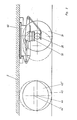
- FIG. 1 and 2 schematically show the separate free steering and lifting of vehicle axles.
- this term also includes axle assemblies.
- a vehicle axle 38 with its wheels 39 is shown schematically in FIG. 1.
- This vehicle axle 38 is mounted on a turntable 40 at a distance 42 from its pivot point 41.
- a steering cylinder 43 is shown schematically for steering the vehicle axle 38.
- a groove formed on the turntable 40 is shown schematically, into which a locking means 46 can engage with a wedge 47 in order to lock the steering in the straight-ahead position.
- One of the vehicle axles can be designed to be liftable with its wheels in order to be brought from the driving position shown in FIG. 2 into the stroke position shown at 44 perennial and 45 ⁇ . Furthermore, the possibility of an axial displacement of the vehicle axis 38 in the longitudinal direction of the vehicle is illustrated in FIG. 2.
- the steering axles can be lifted.
- the steering and lifting axles are arranged according to the desired conditions.
- the arrangement of steering axles enables maneuverability even in confined spaces. In particular, the picking up and taking off of loads such as containers, silos, containers, etc. agreed, places much easier.
- a control valve 49 is shown schematically, which is mounted on an air-sprung axle.
- This control valve 49 controls the pressure in an air suspension. Compressed air is supplied at 58. This compressed air is supplied to the air suspension 50 in a manner controlled by the control valve 49. So far, it has been customary to determine an operating point of the control valve 49 in that the control member of the control valve 49 is connected to an adjusting member 52 via a rocker 51.
- This setting member 52 is set by the vehicle manufacturer and locked in the set position.
- This setting member 52 is designed as an actuating cylinder 55 which is connected to an air pressure control line 59.
- a piston 56 which is acted upon by a return spring 57, is arranged in this actuating cylinder 55.
- the rocker 51 can be brought into the two end positions shown at 53 and 54.
- Different control characteristics of the control valve 49 can thus be set.
- the design of the air suspension according to the invention makes it possible, on the one hand, to limit the overall height of the transport vehicle during transport on a level road to the legally permissible maximum size, or, on the other hand, to adjust the ground clearance required for uneven construction site terrain, if the axle has to be balanced.
- the switching device S After switching on the construction site steering, the switching device S (depending on the gearbox or speedometer) checks whether there is a low driving range, standstill or reversing. If this is the case, hydraulic oil reaches control block H1. Depending on the position, the construction site steering is put into operation or the pre-selection for lifting / lowering the lift axle is made. When operating the construction site steering, the control block H3 is flowed through, and the pilot control can work accordingly. At the same time, the single-track / locking cylinder unlocks. It is flown through the valve R2, the return is made possible through the open valve A4. Valves D3 and D4 are closed. Depending on the steering lever angle in the cab (pilot control), the steering cylinders are activated with H3. Compressed air reaches the additional air locking cylinder via valve A1, which then opens. The compressed air cannot escape through the vent line because D1 is closed.
- the switch H1 If the switch H1 is flipped, the single-track / locking cylinder extends and presses the axis directed at the construction site straight (provided that H2 is in the "lifting" position), the cylinder of the air lock is vented and the locking pawl snaps into the notch of the turntable .
- the lever (which actuates valve H2) also controls the compressed air control, not shown here, for lifting and lowering the trailer axle.
- valve H2 If the valve H2 is brought into the "lowering" position, the one-way / locking cylinder is opened via the check valve R3.
- the valves D3 and D4 are open so that the steering cylinders 1 and 2 act as steering dampers.
- the air lock is opened by the spring pressure of the now lowered lift axle, which allows the otherwise site-controlled axle to rotate freely and then works as a self-steering axle.
- Fig. 5 shows schematically a circuit diagram of a particularly advantageous, preferred embodiment of the electric-hydraulic-pneumatic control of the operating elements of the chassis.
- the hydraulic control circuit has the hydraulic pump 103 driven by the motor 104.
- This hydraulic pump 103 is connected via two hydraulic lines, with the interposition of an electrically controlled hydraulic valve, to the hydraulic steering cylinders 106, which in turn act on the schematically steerable axles 100 for steering.
- An on-off switch 118 for the steering is connected to the voltage source shown schematically at 125 bound.
- the current-carrying line 130 extends from the on-off switch 118 to the operating state test switch 119.
- This operating state test switch 119 checks whether the operating state of the vehicle is compatible with the operation of the steerable elements on the chassis. For example, when there is neither low speed forward, idle, or reverse travel operation, this switch 119 interrupts the live line 130. If a compatible operating condition exists, line 130 remains closed and current is supplied to the motor 104 so that the hydraulic pump 103 in Is put into operation. At the same time, current is supplied to a switch box, shown schematically at 108, so that the steering lever, shown schematically at 109, optionally supplies current via lines 131 to a switching relay 114 for the steering lock.
- the current-carrying line 130 is connected via a button 115 to the electrically operated air control valve 116, which, when the button 115 is depressed, pulls back the pneumatic pawl 117 of the steerable axle 100 and thus releases this steerable axle.
- a lock switch 110 is switched against unauthorized use in such a way that it is necessary to close the control to operate it.
- the steerable axle becomes 100 deflected via the steering cylinder 106.
- the deflection of this steerable axle 100 is determined by the sensors 103 shown and the sensors are connected via control relays 112, in the switch box 108 with indicator lamps 111, for the steering angle.
- These indicator lamps 111 show the driver whether the steerable axle 100 is in the neutral, ie straight-ahead driving position or whether it is turned to the right or left.
- the relay 121 A When the on-off switch 118 is brought into the off position, the relay 121 A is energized in the reset relay module 121 and thereby the relay 121 B of the reset relay module 121 is switched through to the electrically controlled hydraulic valve 105. If one of the two outer sensors 113 that detects a steering lock is energized, i. H. are live, the associated relay 121 B supplies current to the electrically controlled hydraulic valve 105, which is now set so that the hydraulic cylinder 106 returns the steerable axle 100 to the central position. If this middle position is reached, the relay 121 C is excited via the middle sensor and this causes the relay 121 A to drop out. The electrically controlled hydraulic valve 105 returns to the neutral position.
- an electro-pneumatic valve 123 is acted on via line 130 with the interposition of a diode 133. This has the consequence that the air bellows 50 A and the axle lift bellows 102 is vented.
- the axis 107 raised.
- the reverse lock 135 is engaged via the two-stage switch 134 via the valve 136.
- the axis 107 is raised in that the valve 123 is actuated via the line 137.
- the diode 133 prevents an effect on the hydraulic steering.
- a pressure switch 138 is advantageously switched on, which is acted upon by the bellows 50, the axis lying in front of the axis 107, in such a way that it opens when overloaded, so that the axis 107 is automatically lowered into its operating position.
- the steering angle of the freely steerable axle (s) depends on three components for tractor-trailers: - The length ratio between the kingpin and the axles, a constant for the respective trailer, - The freely selectable steering angle of the manually steerable axle (s) and - The position angle of the tractor unit to the trailer.
- manual steering of the trailer can be done via direct manual steering also indirectly bring the other axle (s) to a steering angle regardless of the type of actuation. This enables maneuverability under full load and largely avoids erasing the wheels or tires.
Landscapes
- Engineering & Computer Science (AREA)
- Mechanical Engineering (AREA)
- Chemical & Material Sciences (AREA)
- Combustion & Propulsion (AREA)
- Transportation (AREA)
- Vehicle Body Suspensions (AREA)
- Steering-Linkage Mechanisms And Four-Wheel Steering (AREA)
- Body Structure For Vehicles (AREA)
Priority Applications (1)
| Application Number | Priority Date | Filing Date | Title |
|---|---|---|---|
| AT88730059T ATE68145T1 (de) | 1987-03-10 | 1988-03-10 | Fahrgestell fuer transportfahrzeuge. |
Applications Claiming Priority (6)
| Application Number | Priority Date | Filing Date | Title |
|---|---|---|---|
| DE3707975 | 1987-03-10 | ||
| DE3707975 | 1987-03-10 | ||
| DE3716347 | 1987-05-13 | ||
| DE3716347 | 1987-05-13 | ||
| DE19873718532 DE3718532A1 (de) | 1987-03-10 | 1987-05-29 | Sattelzug mit einem lenkbaren auflieger, ggf. fuer normalen strassenverkehr |
| DE3718532 | 1987-05-29 |
Publications (3)
| Publication Number | Publication Date |
|---|---|
| EP0282442A2 true EP0282442A2 (fr) | 1988-09-14 |
| EP0282442A3 EP0282442A3 (en) | 1989-03-29 |
| EP0282442B1 EP0282442B1 (fr) | 1991-10-09 |
Family
ID=27195590
Family Applications (1)
| Application Number | Title | Priority Date | Filing Date |
|---|---|---|---|
| EP88730059A Expired - Lifetime EP0282442B1 (fr) | 1987-03-10 | 1988-03-10 | Chassis pour véhicule de transport |
Country Status (3)
| Country | Link |
|---|---|
| EP (1) | EP0282442B1 (fr) |
| AT (1) | ATE68145T1 (fr) |
| DE (1) | DE3865325D1 (fr) |
Family Cites Families (4)
| Publication number | Priority date | Publication date | Assignee | Title |
|---|---|---|---|---|
| DE6751093U (de) * | 1968-08-23 | 1969-01-23 | Roman Franz Sauer | Selbstlenkende achse fuer ein strassenfahrzeug |
| US3572676A (en) * | 1968-12-23 | 1971-03-30 | Gen Motors Corp | Fluid spring incorporating fluid medium conserving flow control means |
| GB2137940A (en) * | 1983-04-14 | 1984-10-17 | Geoffrey Ronald Waterton | Container Trailer |
| AT388537B (de) * | 1984-07-16 | 1989-07-25 | Schwarzmueller Wilhelm Gmbh | Sattelzug |
-
1988
- 1988-03-10 AT AT88730059T patent/ATE68145T1/de not_active IP Right Cessation
- 1988-03-10 DE DE8888730059T patent/DE3865325D1/de not_active Expired - Fee Related
- 1988-03-10 EP EP88730059A patent/EP0282442B1/fr not_active Expired - Lifetime
Also Published As
| Publication number | Publication date |
|---|---|
| ATE68145T1 (de) | 1991-10-15 |
| EP0282442B1 (fr) | 1991-10-09 |
| DE3865325D1 (de) | 1991-11-14 |
| EP0282442A3 (en) | 1989-03-29 |
Similar Documents
| Publication | Publication Date | Title |
|---|---|---|
| DD203706A5 (de) | Stabilisierungsvorrichtung fuer fahrzeugachsen | |
| DE102009011606A1 (de) | Vorrichtung und Verfahren zum Durchführen einer Radstandregelung für Nutzfahrzeuge | |
| DE69314242T2 (de) | Lenkgruppe zur Rückwärtsfahrt für eine Selbstlenkachse in Lastkraftwagen, Sattelzügen oder dergleichen | |
| EP0529544B1 (fr) | Semi-remorque avec dispositif de support actionné par un moteur | |
| DE3402442A1 (de) | Lastkraftfahrzeug | |
| EP0186886B1 (fr) | Ensemble tracteur-semi-remorque | |
| DE3533216C2 (fr) | ||
| DE69014648T2 (de) | Zugmaschine. | |
| DE4134501A1 (de) | Lastwagen, insbesondere sattelauflieger | |
| DE3523745A1 (de) | Sattelzug | |
| EP0282442A2 (fr) | Chassis pour véhicule de transport | |
| DE2207063A1 (de) | Gelenkig gekuppelte Zugfahrzeug- und Anhänger-Kombination mit Sicherung gegen Einknicken | |
| DE3522723A1 (de) | Steuersystem fuer gelaendefahrzeug | |
| EP1081021B1 (fr) | Remorque de véhicule à essieu dirigeable | |
| CH675102A5 (fr) | ||
| DE3008461A1 (de) | Nachlaufachse | |
| EP0286576B1 (fr) | Véhicule de transport | |
| DE4331613C2 (de) | Kurzkupplungssystem | |
| DE19635462A1 (de) | 11lfskraftlenkung für Kraftfahrzeuge | |
| DE4119014A1 (de) | Transportfahrzeug zum transport von raumzellen, wie stahlbeton-fertiggaragen | |
| DE102021207439A1 (de) | System und Verfahren zum Lenken eines an eine Sattelkupplung angekuppelten Anhängers | |
| DE102005048321A1 (de) | Antriebseinrichtung | |
| DE4214790A1 (de) | Deaktivierbare Achslenkung | |
| DE69217856T2 (de) | Gezogenes Fahrzeug mit gelenkten Rädern | |
| DE19749226C2 (de) | Geländegängiges Fahrzeug |
Legal Events
| Date | Code | Title | Description |
|---|---|---|---|
| PUAI | Public reference made under article 153(3) epc to a published international application that has entered the european phase |
Free format text: ORIGINAL CODE: 0009012 |
|
| AK | Designated contracting states |
Kind code of ref document: A2 Designated state(s): AT BE DE FR GB IT NL SE |
|
| PUAL | Search report despatched |
Free format text: ORIGINAL CODE: 0009013 |
|
| AK | Designated contracting states |
Kind code of ref document: A3 Designated state(s): AT BE DE FR GB IT NL SE |
|
| 17P | Request for examination filed |
Effective date: 19890920 |
|
| 17Q | First examination report despatched |
Effective date: 19901003 |
|
| GRAA | (expected) grant |
Free format text: ORIGINAL CODE: 0009210 |
|
| AK | Designated contracting states |
Kind code of ref document: B1 Designated state(s): AT BE DE FR GB IT NL SE |
|
| PG25 | Lapsed in a contracting state [announced via postgrant information from national office to epo] |
Ref country code: IT Free format text: LAPSE BECAUSE OF FAILURE TO SUBMIT A TRANSLATION OF THE DESCRIPTION OR TO PAY THE FEE WITHIN THE PRE;WARNING: LAPSES OF ITALIAN PATENTS WITH EFFECTIVE DATE BEFORE 2007 MAY HAVE OCCURRED AT ANY TIME BEFORE 2007. THE CORRECT EFFECTIVE DATE MAY BE DIFFERENT FROM THE ONE RECORDED.SCRIBED TIME-LIMIT Effective date: 19911009 Ref country code: GB Effective date: 19911009 Ref country code: BE Effective date: 19911009 Ref country code: SE Effective date: 19911009 |
|
| REF | Corresponds to: |
Ref document number: 68145 Country of ref document: AT Date of ref document: 19911015 Kind code of ref document: T |
|
| REF | Corresponds to: |
Ref document number: 3865325 Country of ref document: DE Date of ref document: 19911114 |
|
| EN | Fr: translation not filed | ||
| PG25 | Lapsed in a contracting state [announced via postgrant information from national office to epo] |
Ref country code: FR Effective date: 19920228 |
|
| PG25 | Lapsed in a contracting state [announced via postgrant information from national office to epo] |
Ref country code: AT Effective date: 19920310 |
|
| GBV | Gb: ep patent (uk) treated as always having been void in accordance with gb section 77(7)/1977 [no translation filed] | ||
| PLBE | No opposition filed within time limit |
Free format text: ORIGINAL CODE: 0009261 |
|
| STAA | Information on the status of an ep patent application or granted ep patent |
Free format text: STATUS: NO OPPOSITION FILED WITHIN TIME LIMIT |
|
| 26N | No opposition filed | ||
| REG | Reference to a national code |
Ref country code: FR Ref legal event code: ST |
|
| PGFP | Annual fee paid to national office [announced via postgrant information from national office to epo] |
Ref country code: NL Payment date: 19940331 Year of fee payment: 7 |
|
| PG25 | Lapsed in a contracting state [announced via postgrant information from national office to epo] |
Ref country code: NL Effective date: 19951001 |
|
| NLV4 | Nl: lapsed or anulled due to non-payment of the annual fee |
Effective date: 19951001 |
|
| PGFP | Annual fee paid to national office [announced via postgrant information from national office to epo] |
Ref country code: DE Payment date: 19980924 Year of fee payment: 11 |
|
| PG25 | Lapsed in a contracting state [announced via postgrant information from national office to epo] |
Ref country code: DE Free format text: LAPSE BECAUSE OF NON-PAYMENT OF DUE FEES Effective date: 20000101 |