EP0282504B1 - Digitales simulationssystem zur erzeugung von realistischen szenen - Google Patents
Digitales simulationssystem zur erzeugung von realistischen szenen Download PDFInfo
- Publication number
- EP0282504B1 EP0282504B1 EP87905131A EP87905131A EP0282504B1 EP 0282504 B1 EP0282504 B1 EP 0282504B1 EP 87905131 A EP87905131 A EP 87905131A EP 87905131 A EP87905131 A EP 87905131A EP 0282504 B1 EP0282504 B1 EP 0282504B1
- Authority
- EP
- European Patent Office
- Prior art keywords
- data
- data base
- subimage
- image
- resolution
- Prior art date
- Legal status (The legal status is an assumption and is not a legal conclusion. Google has not performed a legal analysis and makes no representation as to the accuracy of the status listed.)
- Expired - Lifetime
Links
Images


Classifications
-
- G—PHYSICS
- G06—COMPUTING OR CALCULATING; COUNTING
- G06T—IMAGE DATA PROCESSING OR GENERATION, IN GENERAL
- G06T1/00—General purpose image data processing
-
- G—PHYSICS
- G06—COMPUTING OR CALCULATING; COUNTING
- G06T—IMAGE DATA PROCESSING OR GENERATION, IN GENERAL
- G06T15/00—Three-dimensional [3D] image rendering
- G06T15/06—Ray-tracing
-
- G—PHYSICS
- G06—COMPUTING OR CALCULATING; COUNTING
- G06T—IMAGE DATA PROCESSING OR GENERATION, IN GENERAL
- G06T15/00—Three-dimensional [3D] image rendering
- G06T15/10—Geometric effects
- G06T15/40—Hidden part removal
-
- G—PHYSICS
- G09—EDUCATION; CRYPTOGRAPHY; DISPLAY; ADVERTISING; SEALS
- G09B—EDUCATIONAL OR DEMONSTRATION APPLIANCES; APPLIANCES FOR TEACHING, OR COMMUNICATING WITH, THE BLIND, DEAF OR MUTE; MODELS; PLANETARIA; GLOBES; MAPS; DIAGRAMS
- G09B9/00—Simulators for teaching or training purposes
- G09B9/02—Simulators for teaching or training purposes for teaching control of vehicles or other craft
- G09B9/08—Simulators for teaching or training purposes for teaching control of vehicles or other craft for teaching control of aircraft, e.g. Link trainer
- G09B9/30—Simulation of view from aircraft
- G09B9/301—Simulation of view from aircraft by computer-processed or -generated image
Definitions
- This invention relates generally to visual and sensor simulation systems and, more particularly, to digital visual and sensor simulation systems useful in providing static or dynamic perspective displays of realistic scenes. These scenes may be of real geographic areas or imaginary areas.
- the eye is the sensor; however, the invention also covers the simulation of infrared (IR) and radar sensor displays.
- IR infrared
- the invention is used to train air (planes, helicopters), sea (ships, submarines), and ground (tanks) personnel.
- the invention is also used for air, ground or sea mission planning, crew preparation, and crew mission training.
- unit computers are linked radially to a central computer to perform a parallel pipeline processing scheme.
- an image frame is generated by means of the ray tracing approach such that the calculation of light intensities for the whole pixles of a frame is shared by the unit computers, each working in parallel with the others.
- the utilized hardware configuration consists of a date base system, a data manipulation system, an inter-computer memory swapping unit, the central computer, a plurality of unit computers, and a frame memory system. All of the unit computers have the same function and are linked radially to the central computer. Further, the unit computers are linked via a data collector to the frame memory system which stores image data for pixles of a frame.
- the central computer divides the screen area into a number of subscreens, and each unit computer performs the same function of calculating the light intensities of the pixles on the subscreen as signed by the central computer, independently of the other unit computers.
- a further advantage of the present invention is that more realistic images are provided since the division of a screen regarded by a viewer in areas of "higher interest” and areas of "lower interest” corresponds to the image impression of a human eye where objects in the centre of the field of view are regarded with high resolution, whereas objects at the boarder of the field of view are viewed with a lower resolution.
- a three-dimensional voxel data base formed by combining three-dimensional digital terrain elevation data with two-dimensional plan view and oblique view aerial photography permits the development of a realistic and cost-effective data base.
- Hidden surfaces are not processed. By processing only visible surfaces, displays can now be produced depicting the nap-of-the-earth as seen in low flight of aircraft or as viewed from ground vehicles. Such displays normally have a large number of hidden surfaces which are not required to be processed in achieving realism. Images produced using this visible surface approach contain real objects (such as buildings and cars) and terrain features providing scene texture. Images are processed using parallel tasks. By employing a large number of parallel tasks (say, 1,000), a large number of slower, very large scale integrated circuit (VLSI) processors may be employed. Alternatively, a smaller number of faster processors can also be used. Still other parallel data processing techniques may be employed. The very large scale integrated processor is both cost-effective and efficient in the execution of instructions and in memory management of a complex memory hierarchy.
- VLSI very large scale integrated circuit
- a separate software task is created for each subimage.
- the code or logic in each task is identical but the input parameters for each subimage vary and the data processed from the data base varies with each task. These tasks can be executed in parallel because they process each subimage independently.
- MIMD multiple instruction stream, multiple data stream
- PD-84076 an instruction-flow type computer
- Any type of image projection system can be employed to project the computer-generated image onto a flat screen, or, onto a screen having the configuration of a dome.
- the ray tracing approach to accessing the data base as disclosed herein can accommodate either linear or nonlinear optics in the projection system, where the nonlinear optics could be designed to match the variable acuity of the eye.
- the central requirement of a computer image generation system is to provide a high fidelity image, particularly in the area of interest.
- the three-dimensional voxel (volume element) algorithm approach used in the present invention is basically different from that of the conventional two-dimensional polygon (surface element) approach.
- the high scene content is displayed in a natural manner, much like that seen by the human eye.
- This approach provides a new method in satisfying image delivery requirements.
- Many problems encountered by current visual systems are eliminated in the arrangement of this invention. For instance, the key requirements of nap-of-the-earth flight for high scene content, coupled with great detail, are addressed parametrically by this parallel voxel approach.
- This approach also handles viewpoint maneuverability, perspective and occultation automatically. Occultation overloads simply cannot occur since only visible surfaces are considered by the algorithm.
- FIG. 1a depicts the general gaming area with the arrow pointing to a particular point of interest which may be a flight corridor directed towards a target area.
- this flight corridor is detailed at an enlarged scale typically representing a flight corridor roughly 200 feet wide in which there is a high area of interest and a second flight corridor, 2,000 feet wide, which depicts an area of lesser interest to the pilot, as the corridor to the target areas is flown.
- FIG. 1c schematically depicts the hierarchical data base that may be generated using this strategy.
- volume elements or voxels are shown in one area of the data base and these correspond to the area of interest in the 200 feet wide flight corridor.
- Lower resolution voxels or volume elements are depicted in another area of the schematic representation of the hierarchical data base and this information would correspond to a lesser detail in the 2,000 feet wide corridor.
- the strategy of maintaining several levels of terrain resolutions and reducing resolution requirements outside of terrain corridors having a high area of interest reduces data base data storage, access and transfer requirements. This also reduces the hardware requirements.
- a data source with several levels of resolution distributed over the gaming area meets the requirements of a nap-of-the-earth computer generated image display system.
- the data base and transfer rates are reduced. This also reduces hardware costs.
- flight corridors such as the 200 foot wide corridor
- resolution of 3.8 arc-minutes supports presentation of each accessory cue, such as identifiable trees, ground cover and buildings.
- a 1/10 of a foot resolution represents 3.0 arc-minutes.
- Data within the flight corridors, but outside the 100 feet distance, may be carried at 1 foot resolution.
- Elements of the gaming area not within the target acquisition or flight corridor areas may be carried at the much lower resolutions of 10 feet or even 100 feet.
- the highest data resolution is 1/10 of a foot. Since a helicopter moves at speeds up to 50 knots, transfer of about 100 feet of new data along a high resolution corridor, such as the 200 foot corridor of FIG. 1b, is required each second. If the corridor of maximum resolution is 200 feet wide, the simulation of a helicopter moving through the corridor requires the transfer of about 10 megabytes per second. Lower resolution data requires a transfer capability of about 6 megabytes per second. For a fighter plane flying at low altitude and high speed the lower resolution data is sufficient to produce the blurred image seen out the window due to objects near the aircraft moving rapidly through the pilot's field of view.
- Extra storage is provided to compensate for seek and latency delays.
- Such storage may be provided on disks. Since seek and latency times reduce the transfer rates, the data base is designed so that these impediments are minimized.
- the terrain is divided along a corridor into equal geographical "tracks," as is seen in FIG. 2.
- the data for each of these tracks resides on separate, physical storage devices and is organized so that movement through a corridor results in the transfer of clustered data, thus minimizing the time required to move the read head of a disk, for example.
- Data is also stored with optimal physical block lengths to overcome the wasteful delays of latency.
- all low resolution data resides in main memory at all times, such as the global virtual memories used in the system, yet to be described, with dynamic transfer of medium and high resolution data as the helicopter negotiates the gaming area. Such transfer is accomplished predictably from a subset of active input-output devices.
- the transfer of medium and high resolution data is used to produce high quality imagery. This requires memory management of the system's memory hierarchy (disks, semiconductor memory, cache memory, registers).
- a memory management system controls the flow of data through the system to provide low and high resolution voxels where and when they are needed.
- the main computer image generating system accesses the data base to compute the projection of the landscape upon the display without overload or transport delay in excess of 100 ms.
- the processing power of the image delivery system is sufficient to meet the update rate for the worst-case of nap-of-the-earth low flight through a scene requiring a high level of detail in the data base.
- occultation overload does not occur.
- the transport time equals the retrace time; therefore, computational time for the worst-case image is invariant for this approach.
- the memory management system only needs to ensure that the relevant data is accessed from storage in a timely manner. This requires the establishment of data buffers in order to compensate for delays due to access times.
- memory management ensures that the data buffers contain terrain data appropriate to the aircraft's motion projected over the next 30 image frames.
- Memory management requires that the hierarchical data segments for the low and high resolution areas be smoothly transferred to physical memory from virtual memory (such as a disk) and that pixel density of the image delivery system corresponds to the area of interest as indicated by the head or helmet sensor as conventionally used in head and eye tracking displays.
- a general multiple-task trainer system requires real time simulation of the outside visual environment correlated with the inside sensor displays, which latter include radar, infrared displays and low light level TV.
- This external environment is composed of static land, sea, and atmospheric features. Also, dynamic sea and atmospheric effects and dynamic objects, such as tanks, ships, planes, helicopters, missiles and other weapon fire must be simulated.
- a simulation system for generating computer images can also be hierarchically decomposed into four types of objects. These are: algorithms and data structures; software; data bases; and hardware. This decomposition is seen in Table I. The interdependence of these four types of objects is apparent from this Table. A key feature evident from Table I is the dependence of the software, data bases, and hardware upon the selection of the processing algorithm and data structures. This dependence is the reason that the multiple instruction stream and multiple data stream computer hardware approach of this invention in implementing this simulation system is radically different from existing pipelined visual and sensor simulation systems.
- the multiple instruction stream/multiple data stream implementation provides for the processing of rays in parallel, the processing of a collection of rays in a subimage in serial fashion permitted in this implementation allows the results of the previous ray's processing (that is, range, for example) to be used to minimize the processing of the next ray.
- a multiple instruction stream/multiple data stream computer system provides a solution to this problem.
- an interconnection network links the data base to parallel data processors.
- the design is one that easily partitions into a small number (10 or less) of distinct, 32-bit very large scale integrated circuits (VLSI) which are extensively replicated in this system.
- VLSI very large scale integrated circuits
- the parallel partitioning of the algorithms is ideally suited to the variable resolutions required by a head and eye tracked, high resolution area-of-interest system design.
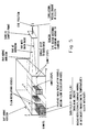
- FIG. 4 is a block diagram of such a system.
- the system has three major subsystems which work in parallel:
- the subimage processors and the object processors are optimized for their tasks, and are not necessarily the same. That is, the subimage processors use a three-dimensional visible surface algorithm with ray tracing (introduced in the discussion with respect to FIG. 5); while the object processors may use either the ray tracing algorithms or a hidden surface algorithm with polygons. While the object processors do not need to share their data bases in the object memories (OM), the subimage processors need access to the large terrain data base stored in the global virtual memory units (GVMU). They access the subset of the data base they need in their global physical memory (GPM), while the global virtual memory units (GVMU) supply the data the global physical memories will need next, through the interconnection network (ICN).
- OM object memories
- GVMU global virtual memory units
- GPM global physical memory
- GVMU global virtual memory units
- the three-dimensional visual surface algorithm processes only visible surfaces, eliminating the occulting overload problem at the design level.
- the algorithm decomposes the screen A into subimages B, where four of the subimages in FIG. 4 are labeled 1 to 4, and processes these subimages independently.
- the algorithm requires no clipping of partially visible surfaces.
- a separate software task, individual tasks 1 to N1 is created for each subimage.
- the code or logic in each task is identical but the input parameters for each subimage vary and the data processed from the data base varies with each task. These tasks can be executed in parallel because they process each subimage independently.
- the algorithm is designed to minimize the logic executed in the average subimage task.
- the subimage processors employ a multiple instruction stream and multiple data stream computer architecture to perform the parallel processing of these tasks, where each of the N1 tasks assigned to the subimage processors may themselves be further decomposed into parallel tasks.
- the three-dimensional visible surface algorithm can be visualized in FIG. 5.
- the position of the viewer's eye and the position of the perimeter of the display surface define the field of view, and potential rays starting at the eye and passing through screen sample points.
- the display surface or screen while shown as planar, also may be curved (e.g., spherical).
- the screen's spatial resolution of picture elements (pixels) and spectral resolution (number of colors and quantization levels per color) define the static quality of a display frame.
- the temporal resolution, or frame update rate (e.g., 30 frames per second), defines the dynamic quality of the display system.
- FIG. 5 shows the data base or gaming area with buildings and the eye position and screen outside the data base.
- the data base is defined over the X, Y plane at the appropriate terrain or object elevation value Z (X, Y).
- the initial position vectors of the eye, E, and the upper left UL, lower left LL, and upper right UR corners of the screen are shown in FIG. 6.
- the algorithm uses the current attitude values of roll, pitch, and yaw to rotate the three corners of the screen about the origin.
- the rotated values are then used to form scaled vectors (U, V) that can be used to compute the position vector of a ray (R), and the normalized ray vector Q.
- the tail of ray vector R is at the eye E, and its head is at the sample point on the screen indexed by multiples of U and V, or R(PIX, LIN) with PIX multiples of U and LIN multiples of V.
- the ray vector is invariant to the translation of the eye to its current position at (EX, EY, EZ).
- This representation of S is analogous to the parametric representation of a line determined by two points (X1, Y1, Z1) and (X2, Y2, Z2), using the parameter t:
- Each ray can be processed in parallel and no hidden surfaces are processed.
- a pseudocode representation of the software which implements the parallel process of stepping along a ray through a hierarchical voxel data base is setforth below.
- the hierarchy has four levels in this example. Range thresholds, TH_L, (where L is 1, 4, 16, 64) are used at each level so that the appropriate coarse resolution color or sensor data is used when the range exceeds these thresholds.
- This algorithm not only models the reflection of visible solar illumination along rays from reflecting surfaces to the viewer's eye, but also models the IR emission and reflection along the same rays being received by an IR sensor or the reflection of radar beams being received by a radar antenna.
- the code that implements the STEP AT LEVEL L for each level in the hierarchy is similar in each case, and is the kernel software of the inner loops which yields the biggest return for optimization.
- the stepping strategy of the algorithm is to step at a coarse resolution until the ray intersects an opaque voxel at that resolution.
- the color values of coarse resolution voxels are averaged over their interior higher resolution voxels.
- the strength of the volume element or voxel approach shown in FIG. 7 resides in the use of real aerial photography merged with digital terrain elevation data, followed by raising objects on the terrain to their appropriate Z values.
- This estimated Z value is fine tuned by adding a computed shadow to the real image and comparing the length of the computed shadow with the real shadow in the image. The Z value is then corrected to make these shadows the same length.
- FIG. 5 also visualizes the hierarchial resolution data structure using two resolutions.
- the state (opaque, transparent, semitransparent) of low resolution volume elements or voxels is stored using two bits. Further memory is required to store the high resolution voxel data, such as color, only if the state is opaque or semitransparent.
- the voxels are randomly accessed as a three-dimensional array using the (X, Y, Z) value of the step vector (S) along the ray.
- S(1) X is decomposable into a four level hierarchy by expressing X as a sum of bit fields: where bit I of the binary representation of X is X(I) and X(I, J) is the bit field going from bit I down to bit J where I.GT.J.
- the three cases shown here have voxels of resoltuions (1, 8, 64, 512), (1, 16, 256, 4096) and (1, 8, 128, 4096), respectively.
- a range buffer approach is used to combine the images of the static data base with dynamic objects. This approach is similar to the popular Z-buffer algorithm.
- the range between the eye and the first opaque voxel along a ray is used to determine which voxel is nearer to the viewer and should be displayed.
- the three-dimensional visible surface display algorithm references the data base using X(I), Y(J) and Z(K) and allows a general distribution of volume elements or voxels at these three-dimensional grid points. This is the highest performance version of the display algorithm, but it also requires the most address computation and the most memory.
- FIG. 7 visualizes the four voxel data structures that correspond to the four cases of the three-dimensional visible surface display algorithm summarized in Table II.
- Case 1 is the same as an image array of picture elements or pixels.
- Cases 2, 3 and 4 require terrain elevation data Z(X, Y), whereas Case 1 has no elevation data.
- a hierarchy of resolutions can be used to minimize the number of steps along a ray. For example, if 1, 10 and 100 foot resolutions are used, then on a 10 foot grid, the maximum value 2 is stored at its 1 foot locations; and on a 100 foot grid the maximum value of Z is stored at its 10 foot locations. Stepping then continues at low resolution when S(3) is above the low resolution value of Z. Stepping at the next higher resolution takes place only when S(3) is less than or equal to the low resolution value of Z.
- Case 2 the aerial photography is registered to the elevation data Z(X, Y) resulting in a smooth continuous mapping onto the real terrain contours.
- objects like buildings, cylindrical storage tanks, or conical (coniferous) trees are recognized, they are grown as discontinuities above this smooth Z(X, Y) surface.
- This growth of objects is shown in Case 2 of FIG. 7.
- the modeling constraint for Case 2 is that objects are always opaque and that there are no color changes in the Z direction over an (X, Y) point. Within this constraint, each of the four walls and the top of the building are different shades of the same color to represent proper sun angle and surface reflectivity.
- Case 3 allows the vertical distribution of opaque voxels to construct objects, such as trees, bushes, or telephone lines that have transparent holes in the vertical direction.
- Table III shows the number of grid points for different gaming area sizes and three different grid resolutions.
- Z 0, 1, . . ., 65535
- An alternate method of building the data base is to use a nested hierarchy of resolutions.
- a 1 x 5 square mile area of interst is modeled at high resolution (1 ft) to support low flight.
- This high resolution area is embedded in a 10 x 50 square mile area at medium resolution (10 ft), and the 10 x 50 square mile area is embedded in a 100 x 500 square mile area at low resolution (100 ft).
- the low resolution data base supports high air-to-air training missions and the high resolution data base supports lower air-to-ground missions.
- the medium resolution data allows a smooth transition in altitude.
- the memory required for this 100 x 500 variable resolution data base is 3 x 420 or 1,260 megabytes (MB) if the data structure of Case 2 is used.
- Dynamic objects are modeled as variations of Case 3 using multiple valued two-dimensional surfaces that are usually continuous.
- the fuselage and wing of a plane are double valued in Z, as are general surfaces like ellipsoids and spheres.
- variable resolutions in the data base allows adaptive sampling along a ray, where sampling using coarse steps occurs through empty space, and sampling using fine steps occurs near opaque surfaces.
- a unique strength of a ray tracing algorithm compared to a polygon algorithm is its ease in solving the image mapping problem.
- This problem involves mapping a planar source image surface, the coordinates of which are (u, v), onto a non-planar display surface through some lens system. Pixels on this source surface, which is like a single frame of movie film, radiate light through the lens system. The lens system then projects and focuses the source pixel onto a unique pixel of the non-planar surface (e.g., a spherical screen).
- the (u, v) pixels of the source surface are indexed by (K, L), then they are mapped onto a unique set of screen pixel coordinates X(K, L), Y(K, L) and Z(K, L). This mapping is determined by the optics of the lens system.
- each of the X, Y and Z screen pixels indexed by K and L are rotated into their corresponding ray vector R(I):
- R(I) RM(I,1) * X(K,L)+RM(I,2) * Y(K,L)+RM(I,3) * Z(K,L) where RM is the rotation matrix.
- the values of X(K, L), Y(K, L) and Z(K, L) can be computed once in a preprocessing mode and stored in memory for table lookup.
- This non-planar screen version of the algorithm requires a rotation transformation on each screen sample point, whereas the flat screen version of the algorithm required rotation of only the three corners of the screen, followed by a linear combination of the U and V screen vectors.
- Image coherence is the two-dimensional property of the image in which two pixels which are close in position are also close in value.
- Data base range coherence is the three-dimensional property that two rays which are close in position have ranges from the eye to their first opaque voxel that are close in value. Optimization for a real time system requires that the property being used for optimization appears in all images. Since image coherence mainly occurs in images of man-made objects at close range with large homogeneous image areas, and image coherence decreases as the range increases so that more objects are projected onto only a few pixels, image coherence is not suitable for optimization of a real time system; however, range coherence occurs in all images.
- the coherence in range does depend upon the roll, pitch and yaw angles. These rotation angles that determine attitude are defined in the description relating to FIG. 6. If roll is zero, so that the top and bottom of the screen are parallel to the horizon, then range is an almost monotonically increasing function as the ray traverses the screen from the bottom to the top of a vertical scan line. The exception occurs when Z(X, Y) increases for objects on the terrain and the pitch is down. The more Z(X, Y) is a gradually changing convex surface, the more range tends to increase monotonically. With a downward pitch angle at the edge of vertical objects like buildings, the range increases and then decreases due to the perspective effect of the top of the building nearer the eye appearing wider than the bottom of the building.
- the image may be decomposed into a grid of square subimages.
- a square subimage may be decomposed into a sequence of concentric square annuli one pixel wide which converge on the pixel in the center of the subimage.
- each inner annulus can use the minimum value of RNG_ 64 obtained from the rays in the adjacent exterior annulus, where RNG_ 64 is the range at which a ray intersected its first opaque coarse resolution (64 units) voxel.
- RNG_ 64 is the range at which a ray intersected its first opaque coarse resolution (64 units) voxel.
- an oversized image is first computed using the correct values of EX, EY, EZ, pitch and yaw. This image is then rotated by the roll angle to produce the correct image. The only pixels in the oversized image that need to be computed are the subset actually used in the rotated image.
- Modulo arithmetic is used to repeat the synthetic and aerial photography data bases indefinitely by converting larger virtual (X, Y) addresses to the physical range; e.g., (722, 515) becomes (210, 3) if the size of the data base is 512 x 512.
- This allows the algorithm to be used with a high density infinite data base which is useful, for example, in simulating a fighter plane flying at low altitude, say 200 feet, with a shallow downward look angle.
- the Data Base Modeling and Analysis System (DBMAS) shown in FIG. 3 consists of multiple data bases and the hardware and software needed to manipulate them.
- the Data Base Management System's (DBMS) software creates, modifies and transforms these data bases.
- the display algorithm requires a data base dependent on volume elements (voxels) as opposed to edges and polygons.
- This voxel display algorithm results in a simpler transformation from a gridded Defense Mapping Agency elevation data base to a simulation data base, since the simulation data base is also gridded.
- This voxel (gridded) data base is used to describe the natural terrain and man-made structures, and is created by digitizing the aerial photographs into a very fine grid. This grid is then overlaid onto the corresponding digital terrain elevation data.
- the voxel data base contains the color (or brightness) information and the elevation value of that location.
- voxel data in a hierarchy of resolutions is created and stored, e.g., 1, 10, and 100.
- the computer image generating system can then process the data at the resolution appropriate to the range between the viewer and the object being viewed.
- the average of the 1 unit resolution data is stored, and at 100 units resolution, the average of the 10 unit resolution data is stored.
- This averaging of voxels to treat range dependent level of detail can be performed automatically, as contrasted with the human decisions on level of detail required by a polygon data base.
- the data base management system DBMS creates a non-real time simulation data base at coarse resolution outside the corridor, and high resolution inside the corridor to support this range dependent variable resolution processing.
- the menu driven data base management software modules are presented below.
- the software design goal was ease of creation of correlated visual and sensor data bases by non-technical personnel.
- the user of this subsystem does not need to know a programming language. After logging on to the system, the user interacts with the menu presented on a CRT and written in English. Each menu displayed would have HELP as the first selectable item. If HELP is selected, some level of information is displayed about that menu.
- modules are self-explanatory, and some are dependent on each other.
- the user might also be using the color palette module, module (8) above.
- the user would query the list of auxiliary analog data module (2.5.2) for aerial photography.
- This computer image generation approach allows solar model or time of day (module 7) information to be added to the data base in a preprocessing mode.
- This information includes direction of illumination, shading of surfaces, shadows of static objects, and temperature to drive IR intensity.
- Atmospheric and weather effects can be added to a given simulation data base using modules 10.1-3.
- a major feature of the all digital approach to data base creation is maintaining correlated simulation data bases. If the application requires the creation of visual, IR, and LLLTV data bases, then they are all created from the same geometric data base. Adding or deleting an object occurs in the geometric data base and is then propagated through to the simulation data bases.
- the hardware to implement the non-real time DMBAS has the same architecture as the real-time hardware of FIG. 4, but can use slower and/or fewer hardware components.
- the subimage processors are composed of off-the-shelf multiprocessors like the Alliant, and a network of these multiprocessors linked by Ethernet are used to tune the system size to the system through-put requirement. These multiprocessors also function as input units or output units, and also support the data base creation software discussed above as well as the simulation software.
- the synthetic data base provides the capability to model flat linear surfaces as well as curved non-linear surfaces, such as circular lakes and cylindrical storage tanks.
- smooth shading is employed and case 2 of the algorithm is used.
- Trees are modeled using cones with random variation in both Z and shade in the rings of voxels that make the cone.
- Interactive data base management software provides for the tracing on the digitized photograph of polygon boundaries of objects (like buildings). A constant Z value is then assigned to the polygon if the object has a flat horizontal roof. The Z value is estimated using the length of the object's shadow.
- the system design objectives for memory management and organization are:
- three-dimensional range coherence is used to minimize both processing and global memory (GM) requests during the stepping along a ray.
- the computation of the image is decomposed into parallel tasks to compute either vertical or square subimages, where the vertical subimage processing involves serial processing from the bottom to the top of the image in a vertical scan line. Since the data is referenced by its (X, Y, Z) location, the data accessed in the field of view of one subimage, in general, is different from data accessed in other subimage fields of view.
- the simulation software therefore satisfies the first set of design objectives.
- the difficult constraints that are faced in this analysis are the real time performance requirement and the performance parameters of semiconductor and rotating disk memory hardware.
- the advantage of the first approach is its independence from disk technology.
- the disadvantage is that the cost of semiconductor memory for the system is proportional to the size of the full data base (e.g., 200 x 200 sq n mi) as opposed to the size of the subset of the data base (e.g., 5 x 20 sq n mi) required to compute the current frame's image.
- the page management approach uses virtual memory subimage processors (SIP) as hardware building blocks.
- the subimage processors are directly connected to the global physical memories (GPM).
- GPS global physical memories
- FIG. 9 The definition of software tasks on the subimage processors and the organization of pages on the global physical memories is presented in FIG. 9 with an implied connection to the global virtual memory units (GVMU).
- GVMU global virtual memory units
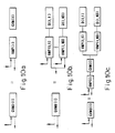
- Three alternate organizations of the global virtual memory units are shown in FIG. 10 to support static and dynamic memory managment.
- a standard memory hierarchy uses a rotating magnetic or optical disk for global virtual memory, dynamic random access memory (DRAM) for global physical memory (GPM), and static random access memory (SRAM) plus registers for local memory (LM), where these memories are listed in order of increasing cost and performance.
- DRAM dynamic random access memory
- SRAM static random access memory
- LM local memory
- FIG. 8 illustrates an implementation of two memory management approaches.
- FIG. 9 illustrates an organization of a global physical memory. In connection with FIG. 9, the following are defined:
- FIG. 10(a) illustrates static memory management. All pages of the data base are interleaved over semiconductor RAM "disks" global virtual memory units GVMU(I) which are controlled by virtual memory processors VMP. This initialization of the global virtual memory unit GVMU(I) occurs before real time processing begins.
- FIGS. 10b and 10c illustrate dynamic memory management using rotating magnetic or optical discs (D) with ND disks on a bus to mask disk access time by the virtual memory processors (VMP).
- the virtual memory processors access single pages of the global virtual memory (GVM) which they store in their buffer random access memory. These pages are ready for high speed transfer by the virtual memory processor to the next stage in the hierarchy.
- FIG. 10b illustrates one level of a virtual memory processor for buffering single pages from disk memory D(I, J) and
- FIG. 10b illustrates two levels of virtual memory processors with the global virtual memory GVM(I) buffering groups of pages required in the next NF frames.
- FIG. 8 a real time visual and sensor simulation system is shown which illustrates static and dynamic memory management.
- the subimage processors (SIP), object processors (OP) and global virtual memory units (GVMU) are under the control of the memory management computer MMC.
- the system is composed of N1 subimage processors where N1 is the number of subimage processors required to compute subimages in real time.
- Each subimage processor has its own global physical memory (GPM) which is connected by an N5 x N6 interconnection network ICN(1) to the subimage processors' global virtual memory units (GVMU) (and there are N6 global virtual memory units, either disk or RAM, plus a controller).
- GPM global physical memory
- ICN(1) the subimage processors' global virtual memory units
- GVMU global virtual memory units
- N6 global virtual memory units, either disk or RAM, plus a controller.
- a task is defined as a number (NV) of adjacent vertical scan lines that get processed serially on a subimage processor (SIP) in a single frame and (NT) is the number of tasks executed in parallel on a subimage processor(SIP).
- N6 There are N2 object processors (OP), each with its nonshared object memory (OM).
- OM nonshared object memory
- IP image processors
- IM image memories
- FB frame buffer memories
- An optional set of N7 global virtual memory units are connected to the image memories (IM) by the interconnection network ICN(3), if the voxel color data is stored here on the image processor's subsystem as opposed to being stored on the subimage processor subsystem where N3 x N7 is assumed.
- the number of disks (D) required to mask page seek and buffer time by the virtual memory processors (VMP) of FIG. 10 is ND.
- the memory management computer does the following:
- VMP virtual memory processors
- ICN unidirectional interconnection networks
- the object processors compute the images and range values of the dynamic objects.
- OP object processors
- point and line objects e.g., landing lights or telephone wires
- the subimage processors (SIP) and the object processors (OP) send to the image processor address arrays indexed by the screen's line and pixel values, and the image processor (IP) uses these addresses, determined from ray traces into the voxel state data base, to fetch color values from the voxel color data base stored on the image memories (IM(I)). Prior to fetching color, the range values are used to resolve hidden surfaces between the subimage processor (SIP(I)) and the object processor (OP(J)). The image processor (IP) then rotates the image by the roll angle and resamples the image for post filtering. In addition, any range dependent effects, like haze, are added by the image processors (IP).
- the number of new pages needed for frame I + 1 is related to maximum flight speed in the horizontal direction over the (X, Y) plane and the maximum yaw rate.
- the yaw rate problem is solved by having the memory management computer (MMC) rotate task assignments to the subimage processors (SIP) as the yaw angle changes. This rotation of task assignments allows many active pages in the global physical memory (GPM(I)) to still be used and only the last subimage processor requires a completely new set of pages.
- MMC memory management computer
- SIP subimage processors
- the memory management computer first tells the virtual memory processors (VMP) to access and send to global physical memory the pages at the bottom of the image and then successive pages from bottom to top. This is no advantage if the pages supplied by the virtual memory processor (VMP) during frame I are not used until frame I + 1. However, when the virtual memory processors supply the pages during frame I to the global physical memories in this bottom-to-top sequence required in frame I, a large savings in the memory requirements of this system results.
- VMP virtual memory processor
- the virtual memory processor (VMP) then sends these pages to the global physical memory (GPM(I)) in this sequence.
- GPS(I) global physical memory
- Another option is to compare the cost of multiple copies of the data base on separate disks accessed by either a single subimage or a small cluster of subimage processors. At one extreme, there is a single copy of the data base on disks, as shown in FIG. 8, but the added cost of the interconnection network is required to crosscouple all subimage processors with the disks. At the other extreme, there is the cost of multiple copies of the data base on separate disks at each subimage processor, but no requirement for an interconnection network or its cost.
Landscapes
- Engineering & Computer Science (AREA)
- Physics & Mathematics (AREA)
- Theoretical Computer Science (AREA)
- General Physics & Mathematics (AREA)
- Computer Graphics (AREA)
- Business, Economics & Management (AREA)
- Educational Administration (AREA)
- Educational Technology (AREA)
- Aviation & Aerospace Engineering (AREA)
- Computer Hardware Design (AREA)
- Geometry (AREA)
- Processing Or Creating Images (AREA)
- Image Generation (AREA)
Claims (23)
- Ein Computerbild-Erzeugungssystem zur Erzeugung kodierter Bildsignale, welche eine ausgewählte Szenerie darstellen, mit:a) Speichervorrichtungen, welche eine dreidimensionale Bilddatenbasis von diskreten Volumenelementen bereitstellen, die individuell verschiedene Subbilder der Szenerie repräsentieren;b) Vorrichtungen zum Zugreifen auf die Datenbasis, um die Daten von all den Subbildern hervorzuholen, die die ausgewählte Szenerie umfassen;c) Vorrichtungen zum Verarbeiten der Daten unter Verwendung einer dreidimensionalen sichtbaren Oberflächentechnik mit einer Strahlengangsbestimmung für jedes Subbild der ausgewählten Szenerie, unabhängig und parallel mit anderen Subbildern der ausgewählten Szenerie; undd) Bilderzeugungsvorrichtungen, welche mit den Vorrichtungen zur Verarbeitung der Daten verbunden sind, um simultan die Daten für alle der Subbilder zu verarbeiten, um kodierte Bildsignale zu erzeugen, die die ausgewählte Szenerie darstellen, dadurch gekennzeichnet, daße) die dreidimensionale Datenbasis Datenbasisstrukturen aus Volumenelementen mit verschiedenen Auflösungen umfaßt, die für eine Datenstruktur mit hierarchischer Auflösung sorgen.
- Das System nach Anspruch 1, worin die Vorrichtungen zum Verarbeiten der Daten umfassen:
eine Mehrzahl von Subbilddatenverarbeitungs-Einrichtungen, um Bilder vom Terrain, statischen Objekten auf dem Terrain und dem Himmel zu errechnen.
Objektdatenverarbeitungs-Einrichtungen, um Bilder von dynamischen Objekten, Punkten, Linien, Zielen und Spezialeffekten sowie dynamischen See- und dynamischen atmosphärischen Effekten zu errechnen; und worin
die Speichervorrichtungen Datenquellen umfassen, die mit den Subbilddatenverarbeitungs-Einrichtungen und den Objektdatenverarbeitungs-Einrichtungen gekoppelt sind, um Bilddaten für die Verarbeitung bereitzustellen; und worin
die Vorrichtungen zum Zugreifen auf die Datenbasis Vorrichtungen zum Steuern umfassen, die mit den Subbilddatenverarbeitungs-Einrichtungen, den Objektdatenverarbeitungs-Einrichtungen und den Datenquellen für die Subbild- und Objektdatenverarbeitungs-Einrichtungen gekoppelt sind, um die Subbilddatenverarbeitungs-Einrichtungen und die Objektdatenverarbeitungs-Einrichtungen bezüglich gegenwärtiger Bilddaten zu steuern und um die Datenquellen für die Subbilddatenverarbeitungs-Einrichtungen bezüglich Bilddaten zu steuern, die als nächstes für die Bilderzeugung benötigt werden. - Das System nach Anspruch 2, in dem die Datenquellen umfassen:
Objektspeicher für die Objektdatenverarbeitungs-Einrichtungen;
globale physikalische Speicher, welche mit den Subbilddatenverarbeitungs-Einrichtungen gekoppelt sind, die Subsätze von Datenbasen enthalten, die für die gegenwärtige Bilddatenverarbeitung benötigt werden;
globale virtuelle Speicher, welche wenigstens eine große Terrain-Datenbasis enthalten; und
Zwischenverbindungsnetzwerke, die die globalen virtuellen Speicher und die globalen physikalischen Speicher koppeln, um Daten an sie anzulegen. - Das System nach Anspruch 2, in dem die Steuervorrichtungen umfassen:
ein Bewegungsrechnersystem, um gegenwärtige und vorhergesagte Anzeigen von Fahrzeugpositionen und - lagen zu erzeugen; und
Vorrichtungen zum Koppeln des Bewegungsrechnersystemes mit den Subbilddatenverarbeitungs-Einrichtungen und den Objektdatenverarbeitungs-Einrichtungen, um eine Steuerung bezüglich den gegenwärtigen Bilddaten bereitzustellen und um das Bewegungsrechnersystem anzukoppeln, um eine Steuerung bezüglich den Daten bereitzustellen, die als nächstes für die Bildverarbeitung und die Anzeige benötigt werden. - Das System nach Anspruch 4, in dem das Bewegungsrechnersystem mit dem globalen virtuellen Speicher gekoppelt ist.
- Das System nach Anspruch 1, worin für jedes Subbild ein separater Software-Task erzeugt wird, wobei der Code oder die Logik in jedem Task identisch ist, aber die Eingabeparameter für jedes Subbild variieren, wobei die Daten, die aus der Datenbasis verarbeitet werden, mit jedem Task variieren, und worin
die Vorrichtungen zum Zugreifen in Übereinstimmung mit den Eingabeparametern für jedes Subbild auf die Datenbasis zugreifen. - Das System nach Anspruch 1, in dem eine Datenbasis einer hohen Auflösung in einer Datenbasis einer geringeren Auflösung eingebettet ist.
- Das System nach Anspruch 1, worin jedes Volumenelement einen Ort innerhalb der Datenbasis aufweist, der der X, Y-Adresse in der Ebene des Teiles der Szenerie entspricht, der durch das Volumenelement repräsentiert wird und auf das mittels ersten und zweiten Schrittpositionsvektorkomponenten in die Datenbasis zugegriffen wird, die jeweils die X- und Y-Werte der Adresse repräsentieren, und mittels einer dritten Schrittpositionsvektorkomponente, die mit den Höhendaten verglichen wird, die in der Datenbasis in Verbindung mit der Adresse gespeichert sind, wobei das Weiterspringen endet, wenn die dritte Schrittpositionsvektorkomponente kleiner oder gleich den Höhendaten ist.
- Das System nach Anspruch 8, in dem die Datenbasis eine Hierarchie von Auflösungen umfaßt und Maximalwerte der Höhendaten bei geringeren Höhenauflösungswerten als die X, Y-Adressenwerte in jeder Hierarchie von Auflösungen gespeichert werden, und das Weiterspringen bei Werten geringer Auflösung wieder beginnt, wenn die dritte Schrittpositionsvektorkomponente sich oberhalb des Wertes geringer Auflösung der Höhendaten befindet.
- Das System nach Anspruch 9, bei dem das Weiterspringen bei der nächsthöheren Auflösung nur dann stattfindet, wenn die dritte Schrittpositionsvektorkomponente kleiner oder gleich dem Wert geringer Auflösung der Höhendaten ist.
- Das System nach Anspruch 8, in dem das ausgewählte Bild in vertikale Abtastlinien zerlegt wird und auf die Datenbasis für alle Höhendaten zugegriffen wird, die mit jedem Volumenelement verbunden sind.
- Das System nach Anspruch 8, in dem das Bild in ein Netz von quadratischen Subbildern zerlegt wird, von denen jedes in eine Sequenz von konzentrischen quadratischen Kreisringen zerlegt wird, und wobei auf die Datenbasis beginnend mit dem Teil zugegriffen wird, der dem äußersten quadratischen Kreisring entspricht, und wobei sequentiell in der Datenbasis bis zu dem Teil fortgefahren wird, der den innersten quadratischen Kreisring repräsentiert.
- Das System nach Anspruch 1, worin die diskreten Volumenelemente der Bilddatenbasis in den Speichervorrichtungen bei bestimmten X, Y-Positionen bereitgestellt werden;
die Volumenelemente gespeicherte Daten enthalten, die die Kontur und die Höhe des Subbildes des Bildes bei der X, Y-Adresse eines jeden Volumenelementes definieren, und worin
Informationsvolumenelemente mit hoher Auflösung in einem Bereich der Datenspeichervorrichtungen und Informationsvolumenelemente geringerer Auflösung in einem anderen Bereich bereitgestellt werden. - Das System nach Anspruch 13, in dem die Informationsvolumenelemente hoher Auflösung Bildauflösungen von ungefähr 1/10 eines Fußes und die Informationsvolumenelemente geringerer Auflösung Bildauflösungen von ungefähr 1 Fuß bis 100 Fuß bereitstellen.
- Ein Verfahren zur Erzeugung kodierter Bildsignale, welche eine ausgewählte Szenerie repräsentieren, welches die Schritte aufweist:a) Entwickeln einer Datenbasis aus Gruppen von Signalzuständen, wobei jede Gruppe von Signalzuständen ein Datenbasisvolumenelement (Voxel) bildet, dessen Signalzustände ein dreidimensionales Subbild der Szenerie repräsentieren;b) Zugreifen auf die Volumenelemente in der Datenbasis, um die Daten von allen Subbildern hervorzuholen, die die ausgewählte Szenerie umfassen;c) Verarbeiten der Daten unter Verwendung einer dreidimensionalen sichtbaren Oberflächentechnik mit einer Strahlengangsbestimmung von jedem zugegriffenen Volumenelement für jedes Subbild der ausgewählten Szenerie unabhängig und parallel mit den Daten für andere Subbilder der ausgewählten Szenerie;d) nachfolgend simultanes Verarbeiten der Daten für alle der Subbilder, um die kodierten Bildsignale zu erzeugen, dadurch gekennzeichnet, daß es desweiteren den Schritt aufweist:e) Bereitstellen der Datenbasis von Gruppen von Signalzuständen mit Datenbasisstrukturen von Volumenelementen mit verschiedenen Auflösungen, wodurch eine Datenstruktur mit hierarchischer Auflösung bereitgestellt wird.
- Das Verfahren nach Anspruch 15, worin jedes Volumenelement einen Ort in der Datenbasis aufweist, der mit dem Netzpunktort des Subbildes der Szenerie identifiziert wird, das durch das Volumenelement repräsentiert wird.
- Das Verfahren nach Anspruch 15, worin der Schritt des Zugreifens auf das Volumenelement in der Datenbasis in Schritten durchgeführt wird, die simultanen Schritten entlang individuellen Strahlen von einem Beobachtungspunkt aus in die Szene projiziert entsprechen.
- Das Verfahren nach Anspruch 15, welches desweiteren die Schritte aufweist:
Bereitstellen eines separaten Tasks für jedes Subbild, in dem die Logik für jeden Task identisch ist;
Verwenden von verschiedenen Eingabeparametern für jeden Task, um auf Daten aus der Datenbasis zuzugreifen, die mit jedem Task variieren;
Durchführen der Tasks und Verarbeiten der Daten in einem hochparallelen Modus, um einen hohen Durchsatz von Daten für ein Realzeitbild bereitzustellen; und
Durchführen der Tasks und Verarbeiten der Daten in einem weniger parallelen Modus, um einen geringeren Datendurchsatz für Nichtrealzeitbilder bereitzustellen. - Das Verfahren nach Anspruch 15, welches desweiteren die Schritte aufweist:
Bereitstellen der Hierarchie der Datenbasisstrukturen mit hohen, mittleren und geringen Datenauflösungen;
Speichern des Mittelwertes der hohen Datenauflösung bei Datenbasisorten von mittlerer Datenauflösung;
Speichern des Mittelwertes der mittleren Datenauflösung bei Datenbasisorten geringer Datenauflösung; und
Zugreifen auf die Datenbasisorte beginnend mit den Orten geringer Datenbasisauflösungen und Zugreifen auf Orte höherer Auflösungen, wenn die Betrachtungsentfernung geringer ist als bestimmte vorhererrechnete Schwellwertentfernungen. - Das Verfahren nach Anspruch 15, worin die Hierarchie der Volumenelemente bei X, Y-Orten bereitgestellt wird, die jeweils Werte der Höhe Z enthalten, welches desweiteren die Schritte aufweist:
Initialisierung einer Sequenz von verschiedenen Zugriffsschritten in die Datenbasis, wobei jeder Zugriffssschritt aus einem Schrittindex 1, einem Schrittindex 2 und einem Schrittindex 3 besteht, worin die Werte der Schrittindizes 1 und 2 sich auf Daten in einem Voxel bei einer spezifischen X, Y-Adresse in der Datenbasis beziehen;
Vergleichen des Wertes des Schrittindexes 3 mit dem Wert von z, der bei der X, Y-Adresse gespeichert ist; und
Beenden der Zugriffsschritte, wenn der Wert des Schrittindexes 3 geringer oder gleich dem Z-Wert bei der X, Y-Adresse ist. - Das Verfahren nach Anspruch 20, worin die dreidimensionale Datenbasis eine einwertige flache zweidimensionale Oberfläche darstellt, welches die Schritte umfaßt:
Initialisierung eines einzelnen Zugriffsschrittes in die Oberflächendatenbasis, bestehend aus dem Schrittindex 1, dem Schrittindex 2 und dem Schrittindex 3, welche Quadraturkomponenten eines Schrittvektors sind, der den Zugriffsschritt definiert; und
Setzen des Schrittindexes 3 auf einen Wert, der der Höhe Null, Z, bei der X, Y-Adresse entspricht. - Das Verfahren nach Anspruch 20, worin die Datenbasis eine einwertige diskontinuierliche zweidimensionale Oberfläche repräsentiert, worin die Schrittindizes 1, 2 und 3 Quadraturkomponenten eines Schrittvektors sind, der die Zugriffsschritte definiert, und worin die X, Y-Adresse in der Datenbasis einem Gitterpunktort eines Subbildes eines anzuzeigenden ausgewählten Bildes entspricht, welches desweiteren den Schritt aufweist
Setzen des Wertes des Schrittindexes 3 auf einen Wert, der eine ausgewählte Höhe bei der X, Y-Adresse repräsentiert. - Das Verfahren nach Anspruch 22, worin die Datenbasis eine einwertige diskontinuierliche zweidimensionale Datenbasis repräsentiert, welche eine Mehrzahl von Höhen Z, Z1, Z2 bei einer X, Y-Adresse aufweist, welches desweiteren den Schritt aufweist
Beenden der Zugriffsschritte, wenn der Wert des Schrittindexes 3 kleiner oder gleich dem Wert von Z bei der X, Y-Adresse ist, oder wenn der Schrittindex 3 gleich Z1 oder Z2 ist.
Applications Claiming Priority (2)
| Application Number | Priority Date | Filing Date | Title |
|---|---|---|---|
| US92585586A | 1986-09-11 | 1986-09-11 | |
| US925855 | 1986-09-11 |
Related Child Applications (2)
| Application Number | Title | Priority Date | Filing Date |
|---|---|---|---|
| EP92101837.0 Division-Into | 1992-02-04 | ||
| EP92101836.2 Division-Into | 1992-02-04 |
Publications (2)
| Publication Number | Publication Date |
|---|---|
| EP0282504A1 EP0282504A1 (de) | 1988-09-21 |
| EP0282504B1 true EP0282504B1 (de) | 1992-10-07 |
Family
ID=25452348
Family Applications (3)
| Application Number | Title | Priority Date | Filing Date |
|---|---|---|---|
| EP19920101837 Withdrawn EP0499874A3 (en) | 1986-09-11 | 1987-07-30 | Digital visual and sensor simulation system for generating realistic scenes |
| EP19920101836 Withdrawn EP0513474A1 (de) | 1986-09-11 | 1987-07-30 | Digitales System für visuelle und Sensorsimulation zur Erzeugung von realistischen Szenen |
| EP87905131A Expired - Lifetime EP0282504B1 (de) | 1986-09-11 | 1987-07-30 | Digitales simulationssystem zur erzeugung von realistischen szenen |
Family Applications Before (2)
| Application Number | Title | Priority Date | Filing Date |
|---|---|---|---|
| EP19920101837 Withdrawn EP0499874A3 (en) | 1986-09-11 | 1987-07-30 | Digital visual and sensor simulation system for generating realistic scenes |
| EP19920101836 Withdrawn EP0513474A1 (de) | 1986-09-11 | 1987-07-30 | Digitales System für visuelle und Sensorsimulation zur Erzeugung von realistischen Szenen |
Country Status (10)
| Country | Link |
|---|---|
| US (1) | US5317689A (de) |
| EP (3) | EP0499874A3 (de) |
| JP (1) | JPH01501178A (de) |
| KR (1) | KR880701922A (de) |
| CA (2) | CA1282173C (de) |
| DE (1) | DE3782160T2 (de) |
| ES (1) | ES2007713A6 (de) |
| IL (3) | IL83616A (de) |
| TR (3) | TR24757A (de) |
| WO (1) | WO1988002156A2 (de) |
Families Citing this family (133)
| Publication number | Priority date | Publication date | Assignee | Title |
|---|---|---|---|---|
| US4972319A (en) * | 1987-09-25 | 1990-11-20 | Delorme David M | Electronic global map generating system |
| US5030117A (en) * | 1987-09-25 | 1991-07-09 | Delorme David M | Digital global map generating system |
| US4876651A (en) * | 1988-05-11 | 1989-10-24 | Honeywell Inc. | Digital map system |
| JPH07504055A (ja) * | 1992-02-18 | 1995-04-27 | エバンス アンド サザーランド コンピューター コーポレーション | テーマ・セルを有している画像テクスチャリング・システム |
| US5469535A (en) * | 1992-05-04 | 1995-11-21 | Midway Manufacturing Company | Three-dimensional, texture mapping display system |
| US5490239A (en) * | 1992-10-01 | 1996-02-06 | University Corporation For Atmospheric Research | Virtual reality imaging system |
| US5751289A (en) * | 1992-10-01 | 1998-05-12 | University Corporation For Atmospheric Research | Virtual reality imaging system with image replay |
| US5422653A (en) * | 1993-01-07 | 1995-06-06 | Maguire, Jr.; Francis J. | Passive virtual reality |
| JPH06223198A (ja) * | 1993-01-26 | 1994-08-12 | Hitachi Ltd | 光線追跡による画像生成装置及び方法 |
| IL108668A (en) * | 1993-02-25 | 1998-09-24 | Hughes Training Inc | A method and system for creating a plurality of 3D image characters |
| US5550959A (en) * | 1993-05-27 | 1996-08-27 | Novalogic, Inc. | Technique and system for the real-time generation of perspective images |
| WO1994029813A1 (en) * | 1993-06-10 | 1994-12-22 | Namco Ltd. | Image synthesizer and apparatus for playing game using the image synthesizer |
| JPH0778267A (ja) * | 1993-07-09 | 1995-03-20 | Silicon Graphics Inc | 陰影を表示する方法及びコンピュータ制御表示システム |
| JPH0757117A (ja) * | 1993-07-09 | 1995-03-03 | Silicon Graphics Inc | テクスチャマップへの索引を生成する方法及びコンピュータ制御表示システム |
| US5729672A (en) * | 1993-07-30 | 1998-03-17 | Videologic Limited | Ray tracing method and apparatus for projecting rays through an object represented by a set of infinite surfaces |
| GB9315852D0 (en) * | 1993-07-30 | 1993-09-15 | Video Logic Ltd | Shading three-dimensional images |
| US5388932A (en) * | 1993-09-13 | 1995-02-14 | Kennametal Inc. | Cutting insert for a milling cutter |
| WO1995010822A1 (en) * | 1993-10-15 | 1995-04-20 | Evans & Sutherland Computer Corporation | Direct rendering of textured height fields |
| US6005581A (en) * | 1994-01-18 | 1999-12-21 | Honeywell, Inc. | Terrain elevation path manager |
| JP3143558B2 (ja) * | 1994-02-02 | 2001-03-07 | キヤノン株式会社 | 画像表示方法および装置 |
| US5699497A (en) * | 1994-02-17 | 1997-12-16 | Evans & Sutherland Computer Corporation | Rendering global macro texture, for producing a dynamic image, as on computer generated terrain, seen from a moving viewpoint |
| CA2144914A1 (en) * | 1994-04-01 | 1995-10-02 | Raymond L. Fitzgerald | Computer graphics texture paging system with fragmentary mip map selection |
| US5493643A (en) * | 1994-05-03 | 1996-02-20 | Loral Aerospace Corp. | Image generator architecture employing tri-level fixed interleave processing and distribution buses |
| GB2295757B (en) | 1994-06-17 | 1998-04-08 | Namco Ltd | Three-dimensional simulator and image synthesis method |
| US5566073A (en) * | 1994-07-11 | 1996-10-15 | Margolin; Jed | Pilot aid using a synthetic environment |
| JPH09512937A (ja) * | 1994-09-06 | 1997-12-22 | ザ リサーチ ファウンデーション オブ ステイト ユニヴァーシティ オブ ニューヨーク | ボリュームを実時間で視覚化する装置及び方法 |
| JP2623449B2 (ja) * | 1994-10-29 | 1997-06-25 | 雅治 石井 | 地形モデル作成方法 |
| IL112940A (en) * | 1995-03-08 | 1998-01-04 | Simtech Advanced Training & Si | Apparatus and method for simulating a terrain and objects thereabove |
| US7453451B1 (en) | 1999-03-16 | 2008-11-18 | Maguire Francis J Jr | Moveable headrest for viewing images from different directions |
| US8330812B2 (en) * | 1995-05-30 | 2012-12-11 | Simulated Percepts, Llc | Method and apparatus for producing and storing, on a resultant non-transitory storage medium, computer generated (CG) video in correspondence with images acquired by an image acquisition device tracked in motion with respect to a 3D reference frame |
| US6181371B1 (en) * | 1995-05-30 | 2001-01-30 | Francis J Maguire, Jr. | Apparatus for inducing attitudinal head movements for passive virtual reality |
| US5913727A (en) * | 1995-06-02 | 1999-06-22 | Ahdoot; Ned | Interactive movement and contact simulation game |
| US5760783A (en) * | 1995-11-06 | 1998-06-02 | Silicon Graphics, Inc. | Method and system for providing texture using a selected portion of a texture map |
| US6437758B1 (en) * | 1996-06-25 | 2002-08-20 | Sun Microsystems, Inc. | Method and apparatus for eyetrack—mediated downloading |
| IL119082A (en) * | 1996-08-16 | 2001-04-30 | Virtue Ltd | A method for creating graphic characters |
| WO1998026306A1 (en) * | 1996-12-09 | 1998-06-18 | Miller Richard L | 3-d weather display and weathercast system |
| US6057847A (en) * | 1996-12-20 | 2000-05-02 | Jenkins; Barry | System and method of image generation and encoding using primitive reprojection |
| US6111582A (en) * | 1996-12-20 | 2000-08-29 | Jenkins; Barry L. | System and method of image generation and encoding using primitive reprojection |
| US6023279A (en) * | 1997-01-09 | 2000-02-08 | The Boeing Company | Method and apparatus for rapidly rendering computer generated images of complex structures |
| US5969723A (en) * | 1997-01-21 | 1999-10-19 | Mcdonnell Douglas Corporation | Method for incorporating high detail normal vector information into polygonal terrain databases and image display system which implements this method |
| US6020893A (en) * | 1997-04-11 | 2000-02-01 | Novalogic, Inc. | System and method for realistic terrain simulation |
| US6028608A (en) * | 1997-05-09 | 2000-02-22 | Jenkins; Barry | System and method of perception-based image generation and encoding |
| US6111583A (en) * | 1997-09-29 | 2000-08-29 | Skyline Software Systems Ltd. | Apparatus and method for three-dimensional terrain rendering |
| US6266063B1 (en) | 1997-10-20 | 2001-07-24 | Baron Services, Inc. | Real-time three-dimensional weather display method and weathercast system |
| US6683609B1 (en) | 1997-10-20 | 2004-01-27 | Baron Services, Inc. | Real-time three-dimensional weather data processing method and system |
| US5959717A (en) * | 1997-12-12 | 1999-09-28 | Chaum; Jerry | Motion picture copy prevention, monitoring, and interactivity system |
| US6298157B1 (en) * | 1998-02-27 | 2001-10-02 | Adobe Systems Incorporated | Locating and aligning embedded images |
| US6456288B1 (en) * | 1998-03-31 | 2002-09-24 | Computer Associates Think, Inc. | Method and apparatus for building a real time graphic scene database having increased resolution and improved rendering speed |
| US6313841B1 (en) * | 1998-04-13 | 2001-11-06 | Terarecon, Inc. | Parallel volume rendering system with a resampling module for parallel and perspective projections |
| US6466185B2 (en) | 1998-04-20 | 2002-10-15 | Alan Sullivan | Multi-planar volumetric display system and method of operation using psychological vision cues |
| US6100862A (en) * | 1998-04-20 | 2000-08-08 | Dimensional Media Associates, Inc. | Multi-planar volumetric display system and method of operation |
| US6377229B1 (en) * | 1998-04-20 | 2002-04-23 | Dimensional Media Associates, Inc. | Multi-planar volumetric display system and method of operation using three-dimensional anti-aliasing |
| US6163756A (en) | 1998-10-20 | 2000-12-19 | Baron Services, Inc. | System and method for detecting and displaying wind shear |
| US6266733B1 (en) * | 1998-11-12 | 2001-07-24 | Terarecon, Inc | Two-level mini-block storage system for volume data sets |
| US6697497B1 (en) | 1998-12-22 | 2004-02-24 | Novell, Inc. | Boundary identification and characterization through density differencing |
| US6373482B1 (en) | 1998-12-23 | 2002-04-16 | Microsoft Corporation | Method, system, and computer program product for modified blending between clip-map tiles |
| US20030158786A1 (en) * | 1999-02-26 | 2003-08-21 | Skyline Software Systems, Inc. | Sending three-dimensional images over a network |
| US6307558B1 (en) * | 1999-03-03 | 2001-10-23 | Intel Corporation | Method of hierarchical static scene simplification |
| US6674922B1 (en) * | 1999-03-26 | 2004-01-06 | Canon Kabushiki Kaisha | Image processing method, image processing apparatus, and storage medium |
| AU2001239926A1 (en) * | 2000-02-25 | 2001-09-03 | The Research Foundation Of State University Of New York | Apparatus and method for volume processing and rendering |
| DE10016765A1 (de) * | 2000-04-04 | 2001-10-11 | Abb Patent Gmbh | System und Verfahren zur Generierung hybrider 2D/3D-Darstellungen von Prozeßzuständen auf einem Flughafenvorfeld |
| IL136430A0 (en) * | 2000-05-29 | 2001-06-14 | Zviaguina Natalia | Ray tracing method and system for determining visible parts of surfaces of three-dimensional objects and their parameters of shading accounting for light and shadow volumes |
| US20020033832A1 (en) * | 2000-09-18 | 2002-03-21 | Rafail Glatman | Method for computer modeling of visual images and wave propagation |
| US8130242B2 (en) * | 2000-11-06 | 2012-03-06 | Nant Holdings Ip, Llc | Interactivity via mobile image recognition |
| US8817045B2 (en) | 2000-11-06 | 2014-08-26 | Nant Holdings Ip, Llc | Interactivity via mobile image recognition |
| JP3819363B2 (ja) * | 2000-11-17 | 2006-09-06 | ドレーガー メディカル システムズ インコーポレイテッド | 完全に統合された集中治療ワークステーション |
| US7187389B2 (en) | 2001-04-12 | 2007-03-06 | International Business Machines Corporation | System and method for simultaneous display of multiple object categories |
| IL143255A (en) | 2001-05-20 | 2015-09-24 | Simbionix Ltd | Endoscopic ultrasonography simulation |
| JP3812368B2 (ja) * | 2001-06-06 | 2006-08-23 | 豊田合成株式会社 | Iii族窒化物系化合物半導体素子及びその製造方法 |
| US6956570B2 (en) | 2001-06-27 | 2005-10-18 | Believe, Inc. | Object visibility control for ray tracing |
| US6670908B2 (en) | 2001-07-31 | 2003-12-30 | Baron Services, Inc. | Automated system and method for processing meteorological data |
| US20030059743A1 (en) * | 2001-08-29 | 2003-03-27 | The Boeing Company | Method and apparatus for automatically generating a terrain model for display during flight simulation |
| US6700573B2 (en) | 2001-11-07 | 2004-03-02 | Novalogic, Inc. | Method for rendering realistic terrain simulation |
| US6906725B2 (en) * | 2002-02-22 | 2005-06-14 | L-3 Communications Corporation | Apparatus and method for simulating sensor imagery |
| US20040243364A1 (en) * | 2002-05-22 | 2004-12-02 | Wendelin Timothy J. | Method and system for modeling solar optics |
| US7015920B2 (en) * | 2003-04-30 | 2006-03-21 | International Business Machines Corporation | Method and system for providing useable images on a high resolution display when a 2D graphics window is utilized with a 3D graphics window |
| US20040243307A1 (en) * | 2003-06-02 | 2004-12-02 | Pieter Geelen | Personal GPS navigation device |
| US7850456B2 (en) | 2003-07-15 | 2010-12-14 | Simbionix Ltd. | Surgical simulation device, system and method |
| JP3789919B2 (ja) | 2004-02-19 | 2006-06-28 | コナミ株式会社 | ゲームプログラム、ゲーム装置及びゲーム方法 |
| US20060164417A1 (en) * | 2004-07-28 | 2006-07-27 | Lockheed Martin Corporation | Imagery-based synthetic environment for computer generated forces |
| US7302364B2 (en) * | 2004-07-30 | 2007-11-27 | The Boeing Company | Methods and systems for advanced spaceport information management |
| US7891978B2 (en) * | 2005-01-13 | 2011-02-22 | International Business Machines Corporation | Search and rescue training simulator |
| KR101019569B1 (ko) | 2005-08-29 | 2011-03-08 | 에브릭스 테크놀로지스, 인코포레이티드 | 모바일 이미지 인식을 통한 상호작용 |
| IL174737A (en) * | 2006-04-03 | 2014-12-31 | Camero Tech Ltd | Device and method for visualizing volume in broadband radar |
| JP4864554B2 (ja) * | 2006-06-12 | 2012-02-01 | 株式会社東芝 | 超音波診断装置、医用画像処理装置、及び医用画像処理プログラム |
| US7898546B1 (en) * | 2006-11-03 | 2011-03-01 | Nvidia Corporation | Logical design of graphics system with reduced shadowed state memory requirements |
| US7768515B1 (en) | 2006-11-03 | 2010-08-03 | Nvidia Corporation | Apparatus, system, and method for reducing shadowed state memory requirements for identifying driver command exceptions in a graphics system |
| CN101617354A (zh) | 2006-12-12 | 2009-12-30 | 埃文斯和萨瑟兰计算机公司 | 用于校准单个调制器投影仪中的rgb光的系统和方法 |
| US8500451B2 (en) | 2007-01-16 | 2013-08-06 | Simbionix Ltd. | Preoperative surgical simulation |
| US8543338B2 (en) | 2007-01-16 | 2013-09-24 | Simbionix Ltd. | System and method for performing computerized simulations for image-guided procedures using a patient specific model |
| US8019736B1 (en) * | 2007-07-25 | 2011-09-13 | Rockwell Collins, Inc. | Systems and methods for combining a plurality of terrain databases into one terrain database |
| US7652620B2 (en) * | 2007-08-09 | 2010-01-26 | Raytheon Company | RCS signature generation for closely spaced multiple objects using N-point models |
| US7646332B2 (en) * | 2007-08-09 | 2010-01-12 | Raytheon Company | Method and apparatus for interleaved gridding in distributed multiple computing for real-time RCS prediction |
| US8213954B2 (en) * | 2007-08-28 | 2012-07-03 | Motorola Solutions, Inc. | Method for addressing user location errors in a cognitive radio system |
| US8358317B2 (en) | 2008-05-23 | 2013-01-22 | Evans & Sutherland Computer Corporation | System and method for displaying a planar image on a curved surface |
| US8702248B1 (en) | 2008-06-11 | 2014-04-22 | Evans & Sutherland Computer Corporation | Projection method for reducing interpixel gaps on a viewing surface |
| US7616151B1 (en) | 2008-06-13 | 2009-11-10 | Raytheon Company | Reducing scattering center data using magnitude-based reduction |
| US7602332B1 (en) | 2008-06-13 | 2009-10-13 | Raytheon Company | Reducing scattering center data using multi-volume aggregation |
| US20100037169A1 (en) * | 2008-08-08 | 2010-02-11 | Eastman Kodak Company | Display of system operating status in a multi-node system |
| US7750842B2 (en) * | 2008-09-18 | 2010-07-06 | Raytheon Company | Parallel processing to generate radar signatures for multiple objects |
| US7880671B2 (en) * | 2008-09-18 | 2011-02-01 | Raytheon Company | Electromagnetic (EM) solver using a shooting bouncing ray (SBR) technique |
| US7567205B1 (en) * | 2008-09-18 | 2009-07-28 | Raytheon Company | Dynamic ray traversing |
| US7592947B1 (en) | 2008-09-18 | 2009-09-22 | Raytheon Company | Generating radar signatures for multiple objects |
| US8077378B1 (en) | 2008-11-12 | 2011-12-13 | Evans & Sutherland Computer Corporation | Calibration system and method for light modulation device |
| US8108147B1 (en) * | 2009-02-06 | 2012-01-31 | The United States Of America As Represented By The Secretary Of The Navy | Apparatus and method for automatic omni-directional visual motion-based collision avoidance |
| KR101004110B1 (ko) * | 2009-05-28 | 2010-12-27 | 주식회사 실리콘아츠 | 레이 트레이싱 코어 및 이를 포함하는 레이 트레이싱 칩 |
| US8419534B2 (en) * | 2009-09-30 | 2013-04-16 | Disney Enterprises, Inc. | Systems and methods for using images to generate gameplay content |
| US8190585B2 (en) * | 2010-02-17 | 2012-05-29 | Lockheed Martin Corporation | Supporting multiple different applications having different data needs using a voxel database |
| US8390508B1 (en) | 2010-04-05 | 2013-03-05 | Raytheon Company | Generating radar cross-section signatures |
| US8589867B2 (en) | 2010-06-18 | 2013-11-19 | Microsoft Corporation | Compiler-generated invocation stubs for data parallel programming model |
| US20110314256A1 (en) * | 2010-06-18 | 2011-12-22 | Microsoft Corporation | Data Parallel Programming Model |
| US8917941B2 (en) * | 2010-09-28 | 2014-12-23 | Siemens Aktiengesellschaft | System and method for shape measurements on thick MPR images |
| FR2974215B1 (fr) * | 2011-04-12 | 2013-10-25 | Real Fusio France | Procede et systeme de rendu d'une scene virtuelle en trois dimensions |
| US9196086B2 (en) * | 2011-04-26 | 2015-11-24 | Here Global B.V. | Method, system, and computer-readable data storage device for creating and displaying three-dimensional features on an electronic map display |
| US9641826B1 (en) | 2011-10-06 | 2017-05-02 | Evans & Sutherland Computer Corporation | System and method for displaying distant 3-D stereo on a dome surface |
| WO2013080439A1 (ja) * | 2011-11-28 | 2013-06-06 | パナソニック株式会社 | 立体画像処理装置及び立体画像処理方法 |
| US9583020B1 (en) * | 2012-11-30 | 2017-02-28 | Rockwell Collins, Inc. | Simulator system for simulating weather |
| US9265458B2 (en) | 2012-12-04 | 2016-02-23 | Sync-Think, Inc. | Application of smooth pursuit cognitive testing paradigms to clinical drug development |
| CN103049649A (zh) * | 2012-12-10 | 2013-04-17 | 江西洪都航空工业集团有限责任公司 | 解决飞行模拟器视景系统天地线匹配问题的算法 |
| US9380976B2 (en) | 2013-03-11 | 2016-07-05 | Sync-Think, Inc. | Optical neuroinformatics |
| WO2016165076A1 (en) * | 2015-04-14 | 2016-10-20 | Chongqing University Of Posts And Telecommunications | Method and system for image enhancement |
| US9990335B2 (en) * | 2016-06-27 | 2018-06-05 | The United States Of America As Represented By The Administrator Of The National Aeronautics And Space Administration | Universal and automated monte carlo method code for uncertainty propagation in metrology databases |
| US10420999B2 (en) | 2017-03-27 | 2019-09-24 | Intel Corporation | Sensor-derived object flight performance tracking |
| US10409638B2 (en) | 2017-04-10 | 2019-09-10 | Bank Of America Corporation | Digital processing system for event and/or time based triggering management, and control of tasks |
| US11064184B2 (en) | 2017-08-25 | 2021-07-13 | Aurora Flight Sciences Corporation | Aerial vehicle imaging and targeting system |
| US11074827B2 (en) | 2017-08-25 | 2021-07-27 | Aurora Flight Sciences Corporation | Virtual reality system for aerial vehicle |
| US10495421B2 (en) | 2017-08-25 | 2019-12-03 | Aurora Flight Sciences Corporation | Aerial vehicle interception system |
| US10459445B2 (en) * | 2017-09-28 | 2019-10-29 | Intel IP Corporation | Unmanned aerial vehicle and method for operating an unmanned aerial vehicle |
| CN108111784B (zh) * | 2017-12-22 | 2020-06-26 | 成都先锋材料有限公司 | 一种生物活体影像监控系统 |
| US11988549B2 (en) * | 2018-09-20 | 2024-05-21 | Hook Mountain Software Develoment, Inc. | Apparatus, methodologies and software applications for determining a level of direct sunlight |
| FR3095533B1 (fr) | 2019-04-26 | 2021-05-07 | Thales Sa | Procede et dispositif electronique de gestion de l'affichage d'un profil de vol d'un aeronef avec selection de resolution(s) adaptees(s) de base(s) de donnees terrain, programme d'ordinateur et systeme electronique d'affichage assoocies |
| US11436761B2 (en) * | 2020-03-18 | 2022-09-06 | International Business Machines Corporation | Preventing feature loss when compressing images |
| CN116863060B (zh) * | 2023-07-18 | 2025-05-16 | 西北大学 | 一种基于多分辨率网格的目标红外计算方法 |
Family Cites Families (19)
| Publication number | Priority date | Publication date | Assignee | Title |
|---|---|---|---|---|
| US4017985A (en) * | 1975-08-22 | 1977-04-19 | General Electric Company | Multisensor digital image generator |
| CA1141468A (en) * | 1979-06-15 | 1983-02-15 | Martin J.P. Bolton | Visual display apparatus |
| US4616217A (en) * | 1981-05-22 | 1986-10-07 | The Marconi Company Limited | Visual simulators, computer generated imagery, and display systems |
| US4489389A (en) * | 1981-10-02 | 1984-12-18 | Harris Corporation | Real time video perspective digital map display |
| US4660157A (en) * | 1981-10-02 | 1987-04-21 | Harris Corporation | Real time video perspective digital map display method |
| NL8300872A (nl) * | 1983-03-10 | 1984-10-01 | Philips Nv | Multiprocessor-rekenmachinesysteem voor het tot een gekleurde afbeelding verwerken van in een hierarchische datastruktuur gedefinieerde objekt-elementen. |
| EP0100097B1 (de) * | 1982-07-30 | 1991-01-30 | Honeywell Inc. | Rechnergesteuertes Abbildungssystem |
| US4622632A (en) * | 1982-08-18 | 1986-11-11 | Board Of Regents, University Of Washington | Data processing system having a pyramidal array of processors |
| US4727474A (en) * | 1983-02-18 | 1988-02-23 | Loral Corporation | Staging memory for massively parallel processor |
| US4682160A (en) * | 1983-07-25 | 1987-07-21 | Harris Corporation | Real time perspective display employing digital map generator |
| US4590569A (en) * | 1983-10-14 | 1986-05-20 | Navigation Sciences Inc. | Navigation system including an integrated electronic chart display |
| US4583185A (en) * | 1983-10-28 | 1986-04-15 | General Electric Company | Incremental terrain image generation |
| US4625290A (en) * | 1983-11-02 | 1986-11-25 | University Of Florida | Apparatus and method for producing a three-dimensional display on a video display device |
| US4694404A (en) * | 1984-01-12 | 1987-09-15 | Key Bank N.A. | High-speed image generation of complex solid objects using octree encoding |
| US4685070A (en) * | 1984-08-03 | 1987-08-04 | Texas Instruments Incorporated | System and method for displaying, and interactively excavating and examining a three dimensional volume |
| US4847788A (en) * | 1985-03-01 | 1989-07-11 | Hitachi, Ltd. | Graphic data processing method and system |
| US4641255A (en) * | 1985-05-22 | 1987-02-03 | Honeywell Gmbh | Apparatus for simulation of visual fields of view |
| SE445154B (sv) * | 1985-07-08 | 1986-06-02 | Ibm Svenska Ab | Metod for att avlegsna dolda linjer |
| US4805121A (en) * | 1986-05-30 | 1989-02-14 | Dba Systems, Inc. | Visual training apparatus |
-
1987
- 1987-07-30 JP JP62504620A patent/JPH01501178A/ja active Pending
- 1987-07-30 DE DE8787905131T patent/DE3782160T2/de not_active Expired - Fee Related
- 1987-07-30 WO PCT/US1987/001812 patent/WO1988002156A2/en not_active Ceased
- 1987-07-30 EP EP19920101837 patent/EP0499874A3/en not_active Withdrawn
- 1987-07-30 EP EP19920101836 patent/EP0513474A1/de not_active Withdrawn
- 1987-07-30 EP EP87905131A patent/EP0282504B1/de not_active Expired - Lifetime
- 1987-08-11 CA CA000544219A patent/CA1282173C/en not_active Expired - Lifetime
- 1987-08-23 IL IL83616A patent/IL83616A/xx unknown
- 1987-09-10 ES ES8702612A patent/ES2007713A6/es not_active Expired
- 1987-09-11 TR TR89/0433A patent/TR24757A/xx unknown
- 1987-09-11 TR TR89/0432A patent/TR24961A/xx unknown
- 1987-09-11 TR TR87/0635A patent/TR24581A/xx unknown
-
1988
- 1988-05-10 KR KR1019880700518A patent/KR880701922A/ko not_active Ceased
-
1990
- 1990-07-13 CA CA000615789A patent/CA1299755C/en not_active Expired - Lifetime
- 1990-08-10 US US07/565,864 patent/US5317689A/en not_active Expired - Fee Related
-
1991
- 1991-03-04 IL IL97422A patent/IL97422A0/xx unknown
- 1991-03-04 IL IL97421A patent/IL97421A0/xx unknown
Non-Patent Citations (3)
| Title |
|---|
| Computer Graphics 80, August 1980, (Fareham, Hants, GB), T. Rowley: "Computer generated imagery for training simulators", pages 223-232, see page 228, paragraphs 1-5 * |
| Proceedings IECON 84, Industrial Applications of Micro-Electronics, 22-26 October 1984, IEEE (Tokyo, Papan), H. Nishimura et al.: "A multicomputer system links: its architecture and graphics applications" pages 270-274, see page 271; page 272, till right-hand column, line 10 * |
| Proceedings of the IEEE 1984 National Aerospace and Electronics Conferemce, Naecon 1984, 21-25 May 1984, volume 2 of 2, IEEE (US) O. Marvel et al.: "Image synthesization for simulation, stimulation and training", pages 884-900, see figure 5; page 887, Paragraph "VSCDP" * |
Also Published As
| Publication number | Publication date |
|---|---|
| TR24961A (tr) | 1992-07-29 |
| ES2007713A6 (es) | 1989-07-01 |
| WO1988002156A2 (en) | 1988-03-24 |
| EP0513474A1 (de) | 1992-11-19 |
| IL97422A0 (en) | 1992-06-21 |
| TR24581A (tr) | 1991-11-27 |
| KR880701922A (ko) | 1988-11-07 |
| JPH01501178A (ja) | 1989-04-20 |
| CA1299755C (en) | 1992-04-28 |
| IL97421A0 (en) | 1992-06-21 |
| EP0282504A1 (de) | 1988-09-21 |
| EP0499874A3 (en) | 1992-10-28 |
| IL83616A (en) | 1992-11-15 |
| DE3782160D1 (de) | 1992-11-12 |
| US5317689A (en) | 1994-05-31 |
| EP0499874A2 (de) | 1992-08-26 |
| WO1988002156A3 (en) | 1988-08-25 |
| DE3782160T2 (de) | 1993-02-11 |
| TR24757A (tr) | 1992-03-09 |
| CA1282173C (en) | 1991-03-26 |
Similar Documents
| Publication | Publication Date | Title |
|---|---|---|
| EP0282504B1 (de) | Digitales simulationssystem zur erzeugung von realistischen szenen | |
| US6747649B1 (en) | Terrain rendering in a three-dimensional environment | |
| US4667190A (en) | Two axis fast access memory | |
| US4835532A (en) | Nonaliasing real-time spatial transform image processing system | |
| Yan | Advances in computer-generated imagery for flight simulation | |
| US4645459A (en) | Computer generated synthesized imagery | |
| KR0172462B1 (ko) | 렌더링 및 와핑 영상 생성 시스템 및 방법 | |
| US5630718A (en) | Weather simulation system | |
| US5598359A (en) | Weather effects generator for simulation systems | |
| US4807158A (en) | Method and apparatus for sampling images to simulate movement within a multidimensional space | |
| US5409379A (en) | Weather simulation system | |
| US4965753A (en) | System for constructing images in 3-dimension from digital data to display a changing scene in real time in computer image generators | |
| US5135397A (en) | 3-d weather for digital radar landmass simulation | |
| EP0100097B1 (de) | Rechnergesteuertes Abbildungssystem | |
| EP0313101A2 (de) | Fraktionierte Pixelabbildung in einem rechnergesteuerten Abbildungssystem | |
| CA2617373C (en) | Improved terrain rendering in a three-dimensional environment | |
| Mueller | Architectures of image generators for flight simulators | |
| CA1206260A (en) | Image processing system | |
| JPH0154749B2 (de) | ||
| Ferguson | High-performance computer image generation: a marriage of computer graphics and image processing | |
| Rowley | Computer generated imagery for training simulators | |
| Southard | Superworkstations for Terrain Visualization: A Prospectus | |
| Lisle et al. | A Characterization of low cost simulator image generation systems | |
| Vince | The art of simulation | |
| Weiman | Advanced Weapon System (AWS) Sensor Prediction Techniques Study. Volume I |
Legal Events
| Date | Code | Title | Description |
|---|---|---|---|
| PUAI | Public reference made under article 153(3) epc to a published international application that has entered the european phase |
Free format text: ORIGINAL CODE: 0009012 |
|
| 17P | Request for examination filed |
Effective date: 19880505 |
|
| AK | Designated contracting states |
Kind code of ref document: A1 Designated state(s): CH DE FR GB IT LI SE |
|
| D17D | Deferred search report published (deleted) | ||
| 17Q | First examination report despatched |
Effective date: 19900626 |
|
| GRAA | (expected) grant |
Free format text: ORIGINAL CODE: 0009210 |
|
| AK | Designated contracting states |
Kind code of ref document: B1 Designated state(s): CH DE FR GB IT LI SE |
|
| XX | Miscellaneous (additional remarks) |
Free format text: TEILANMELDUNG 92101836.2 EINGEREICHT AM 30/07/87. |
|
| REF | Corresponds to: |
Ref document number: 3782160 Country of ref document: DE Date of ref document: 19921112 |
|
| ET | Fr: translation filed | ||
| ITF | It: translation for a ep patent filed | ||
| PLBE | No opposition filed within time limit |
Free format text: ORIGINAL CODE: 0009261 |
|
| STAA | Information on the status of an ep patent application or granted ep patent |
Free format text: STATUS: NO OPPOSITION FILED WITHIN TIME LIMIT |
|
| 26N | No opposition filed | ||
| PGFP | Annual fee paid to national office [announced via postgrant information from national office to epo] |
Ref country code: GB Payment date: 19940620 Year of fee payment: 8 |
|
| EAL | Se: european patent in force in sweden |
Ref document number: 87905131.6 |
|
| PGFP | Annual fee paid to national office [announced via postgrant information from national office to epo] |
Ref country code: FR Payment date: 19950612 Year of fee payment: 9 |
|
| PGFP | Annual fee paid to national office [announced via postgrant information from national office to epo] |
Ref country code: SE Payment date: 19950619 Year of fee payment: 9 |
|
| PGFP | Annual fee paid to national office [announced via postgrant information from national office to epo] |
Ref country code: DE Payment date: 19950620 Year of fee payment: 9 |
|
| PGFP | Annual fee paid to national office [announced via postgrant information from national office to epo] |
Ref country code: CH Payment date: 19950622 Year of fee payment: 9 |
|
| PG25 | Lapsed in a contracting state [announced via postgrant information from national office to epo] |
Ref country code: GB Effective date: 19950730 |
|
| GBPC | Gb: european patent ceased through non-payment of renewal fee |
Effective date: 19950730 |
|
| PG25 | Lapsed in a contracting state [announced via postgrant information from national office to epo] |
Ref country code: SE Effective date: 19960731 Ref country code: LI Effective date: 19960731 Ref country code: CH Effective date: 19960731 |
|
| REG | Reference to a national code |
Ref country code: CH Ref legal event code: PL |
|
| PG25 | Lapsed in a contracting state [announced via postgrant information from national office to epo] |
Ref country code: FR Effective date: 19970328 |
|
| PG25 | Lapsed in a contracting state [announced via postgrant information from national office to epo] |
Ref country code: DE Effective date: 19970402 |
|
| EUG | Se: european patent has lapsed |
Ref document number: 87905131.6 |
|
| REG | Reference to a national code |
Ref country code: FR Ref legal event code: ST |
|
| PG25 | Lapsed in a contracting state [announced via postgrant information from national office to epo] |
Ref country code: IT Free format text: LAPSE BECAUSE OF NON-PAYMENT OF DUE FEES;WARNING: LAPSES OF ITALIAN PATENTS WITH EFFECTIVE DATE BEFORE 2007 MAY HAVE OCCURRED AT ANY TIME BEFORE 2007. THE CORRECT EFFECTIVE DATE MAY BE DIFFERENT FROM THE ONE RECORDED. Effective date: 20050730 |