EP0282764A2 - Arrangement de circuit pour alimenter du réseau de tension continu d'un moteur synchrone à courant polyphasé - Google Patents
Arrangement de circuit pour alimenter du réseau de tension continu d'un moteur synchrone à courant polyphasé Download PDFInfo
- Publication number
- EP0282764A2 EP0282764A2 EP19880102547 EP88102547A EP0282764A2 EP 0282764 A2 EP0282764 A2 EP 0282764A2 EP 19880102547 EP19880102547 EP 19880102547 EP 88102547 A EP88102547 A EP 88102547A EP 0282764 A2 EP0282764 A2 EP 0282764A2
- Authority
- EP
- European Patent Office
- Prior art keywords
- voltage
- circuit arrangement
- capacitor
- input
- frequency converter
- Prior art date
- Legal status (The legal status is an assumption and is not a legal conclusion. Google has not performed a legal analysis and makes no representation as to the accuracy of the status listed.)
- Granted
Links
Images

Classifications
-
- H—ELECTRICITY
- H02—GENERATION; CONVERSION OR DISTRIBUTION OF ELECTRIC POWER
- H02P—CONTROL OR REGULATION OF ELECTRIC MOTORS, ELECTRIC GENERATORS OR DYNAMO-ELECTRIC CONVERTERS; CONTROLLING TRANSFORMERS, REACTORS OR CHOKE COILS
- H02P6/00—Arrangements for controlling synchronous motors or other dynamo-electric motors using electronic commutation dependent on the rotor position; Electronic commutators therefor
- H02P6/14—Electronic commutators
- H02P6/16—Circuit arrangements for detecting position
- H02P6/18—Circuit arrangements for detecting position without separate position detecting elements
- H02P6/185—Circuit arrangements for detecting position without separate position detecting elements using inductance sensing, e.g. pulse excitation
Definitions
- the invention relates to a circuit arrangement for operating a synchronous motor having a multi-phase armature winding on a DC voltage network of the type defined in the preamble of claim 1.
- the switching device for successively connecting the individual winding phases of the four-phase armature winding is implemented by current valves, one of which is connected in series with a winding phase of the armature winding arranged here in the stator is and lies between the one winding phase end and the zero potential.
- the other winding phase ends of the armature winding are combined to form a star point and a power switch on the Plus potential of the DC voltage network connected.
- the switching signal generator and the logic stage for the consequent activation of the current valves are implemented by voltage comparators, by logic logic elements and by a ring counter, the parallel counting outputs of which are connected to the control inputs of the current valves.
- the voltage comparators the voltages induced as a result of blocked current valves in cyclically successive winding phases are compared with one another and an output signal is output in each case when the voltage induced in the cyclically following winding phase is greater than the voltage induced in the cyclically preceding winding phase.
- an auxiliary clock generator which starts the ring counter to start the motor and advances in very slow steps of, for example, 0.5 sec. As soon as the direction of rotation of the If the rotor, counter reading of the ring counter and voltage intersections of the induced AC voltages match, the synchronous motor goes into self-control and accelerates with maximum torque up to the operating speed.
- the circuit arrangement according to the invention with the characterizing features of claim 1 has the advantage that it is relatively simple and does not require any complex electronics for voltage comparison and logic operation.
- the voltage-frequency converter generates switching pulses whose repetitive frequency gradually increases from zero.
- the switching impulses initially cause a very slow cyclical indexing of the switching device in the armature winding, so that the rotor can align itself with certainty and start up in the prescribed direction of rotation.
- the rotor is turned increasingly faster until it reaches the synchronous speed when the maximum possible voltage is applied to the input of the voltage-frequency converter. If the motor falls out of step, the start element is activated, which briefly lowers the voltage at the input of the voltage-frequency converter to zero and then, depending on the time, increases again to the final voltage value. The rotor runs back to synchronism.
- the circuit arrangement according to the invention is very simple.
- the voltage-frequency converter can according to the embodiment of the invention according to claim 4 as
- the voltage-controlled oscillator (VCO) and the starting element can be designed according to the exemplary embodiment of the invention in claim 2 as a simple capacitor which is charged to a predetermined final voltage via a resistor from zero when the motor is switched on and after the motor drops out.
- the restart unit is implemented according to the embodiment of the invention according to claim 3 by a NAND-Schmitt trigger with two logic inputs, one of which is assigned a control voltage derived from the motor current and the other of which is assigned a control voltage proportional to the capacitor voltage.
- the control voltage derived from it reaches the switch-on threshold of the Schmitt trigger. This switches through when the capacitor is charged and sets the control input of the VCO to zero. The capacitor is short-circuited and discharged, the control voltage at the Schmitt trigger, derived from the capacitor voltage, dropping in the same way. As soon as this control voltage falls below the switch-off threshold of the Schmitt trigger, the Schmitt trigger locks again and the charging process of the capacitor and the associated starting process of the rotor start.
- the logic circuit can be implemented according to the embodiment of the invention in claim 7 by a simple ring counter, at the counting input of which the rectangular pulses of the VCO are present directly or indirectly as counting pulses.
- the armature winding arranged in the stator of the synchronous motor is designated by 10.
- the armature winding is three-phase with the winding strands 11, 12 and 13.
- the rotor, not shown, of the synchronous motor has at least two poles and is equipped with permanent magnets.
- the one ends of the winding phases 11, 12, 13 are combined to form a star point 14 and are connected via a resistor 15 to the negative potential of a DC voltage network, which is represented in FIG. 1 by the DC voltage source 16.
- the other ends of the winding phases 11-13 are each connected to the positive potential of the DC voltage network 16 via an electronic current valve 17, 18, 19 of a switching device 20 and via an on / off switch 21.
- the electronic current valves 17-19 can be designed, for example, as power transistors or power amplifiers.
- the individual winding phases 11-13 of the armature winding 10 are successively connected to the DC voltage network 16 by appropriate activation of the switching device 20.
- the circuit arrangement has a switching signal generator 22 for generating switching signals for the switching device and a logic stage 23 connected between the switching signal generator 22 and the switching device 20, which ensures the logical assignment of the switching device with the switching signals.
- the switching signal generator 22 has a voltage-frequency converter 24, a starting element 25 connected upstream thereof and a restarting unit 26 effective after the synchronous motor has started up.
- the voltage-frequency converter 24, which is designed here as a voltage-controlled oscillator 27, hereinafter referred to as VCO 27 for short, generates at its output a rectangular pulse train, the pulse repetition frequency of which is dependent on the voltage level at the control input of the VCO 27.
- the starting element 25 is started on the one hand when the mains voltage is switched on, that is to say when the on / off switch 21 is closed, and on the other hand by the restart unit 26. With the start of the starting element 25, the voltage at the input of the voltage-frequency converter 24 or at the control input of the VCO 27 increases from zero to a preset value.
- the starting element 25 is formed by a capacitor 28 which is charged via at least one resistor.
- the capacitor voltage is the control voltage at the control input of the VCO 27.
- the restart unit 26 consists of an inverting Schmitt trigger 29 with two logic inputs 291 and 292.
- One input 291 has a resistor 15 between the star point 14 of the armature winding 10 and the zero potential of the DC voltage network 16 tapped control voltage, which is proportional to the motor current.
- At the input 292 there is a control voltage proportional to the capacitor voltage of the capacitor 28, which is generated by a capacitor 30 is generated.
- the output of the Schmitt trigger 29 is connected to the control input of the VCO 27, at which the one capacitor connection of the capacitor 28 is also located.
- a voltage divider 31 with the resistors 32 - 34 and the two voltage taps 35, 36 is connected to the DC voltage network 16 via the on / off switch 21.
- the higher potential first voltage tap 35 of the voltage divider 31 is connected to the control input of the VCO 27, to the output of the Schmitt trigger 29 and to the capacitor connection of the capacitor 28 connected thereto.
- the potential-lower voltage tap 36 lies together with the one capacitor connection of the capacitor 30 at the second logic input 292 of the Schmitt trigger 29.
- the other capacitor connection of the two capacitors 28, 30 is connected to the zero potential of the DC voltage network 16.
- the logic stage 23 is designed as a simple ring counter 37 with three parallel outputs.
- the three outputs are connected to the control inputs of the three current valves 17, 18, 19.
- the rectangular pulses of the VCO 27 are counting pulses at the counting or clock input of the ring counter 37. With each counting pulse, the ring counter 37 counts one step further, the output potentials at the individual outputs of the ring counter 37 successively switching from logic L to logic H and vice versa. Only one counting output leads to H potential. If the counter reading "3" is reached, the ring counter 37 is automatically reset.
- the synchronous motor stands still and the capacitors 28, 30 are discharged.
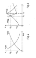
- the on / off switch 21 is closed, the motor is switched on. About the voltage divider 31 Capacitor 28 and also capacitor 30 are charged. The voltage curve across the capacitor 30 is shown in Fig. 2 over time t or speed n of the synchronous motor and designated U229. The voltage curve across the capacitor 28 is approximately proportional to this.
- the control voltage of the VCO 27 thus gradually increases from zero until it has reached its final value determined by the voltage divider 31.
- the VCO 27 generates square-wave pulses, the repetition frequency of which gradually increases.
- the ring counter 37 is initially advanced very slowly and increasingly faster.
- the winding phases 11-13 of the armature winding 10 are placed one after the other and with increasing speed over the respectively conductive current valve 17-19 to the mains DC voltage. Since the advance of the individual winding phases 11-13 takes place very slowly at first, the rotor can align itself with certainty and rotate in the correct direction of rotation with the slowly progressing rotating field. The rotor accelerates with increasing frequency of the square-wave pulses, the increasing frequency of switching the winding phases 11-13 and the rotating field thus rotating faster. If the maximum value of the capacitor voltage across the capacitor 28 predetermined by the voltage divider 31 is reached, the rectangular pulse train of the VCO 27 has a constant pulse repetition frequency and the rotor rotates at a synchronous speed.
- the resistance 15 between the star point 14 of the armature winding 10 and the zero potential of the DC voltage network 16 is traversed by the relatively high inrush current I, which decreases with increasing speed n of the rotor.
- the voltage curve across the resistor 15 and thus at the logic input 291 of the Schmitt trigger 29 is also shown in Fig. 2 and designated U291. 2 is the switch-on voltage U E and Switch-off voltage U A of the Schmitt trigger 29 is shown in dashed lines. If the switch-on voltage U E is exceeded at both control inputs 291, 292, the Schmitt trigger 29 switches on and its output becomes logic "O".
- the motor current I which flows through the resistor 15, increases very sharply.
- the course of the control voltages at the two logic inputs 291 and 292 is shown in FIG. 3 for this case.
- the control voltage applied by the capacitor 30 U292 is initially constant because of the constant charging of the capacitor 30 and greater than the switch-on voltage U E of the Schmitt trigger 29, while the voltage tapped at the resistor 15 U291 increases with the increasing motor current I and finally in points t1 the switch-on voltage U E of the Schmitt trigger 29 also exceeds.
- the Schmitt trigger 29 switches on at this moment and sets the control input of the VCO 27 to zero.
- the capacitors 28 and 30 are thus discharged.
- the control voltage U291 continues to rise with the motor current I
- the control voltage U292 drops relatively quickly with the discharge of the capacitor 30 and falls below the switch-off voltage U A of the Schmitt trigger 29 at the time t2.
- the Schmitt trigger 29 thus switches off again, and the capacitors 28 and 30 are recharged via the voltage divider 31.
- the increasing control voltage at the control input of the VCO 27 allows the frequency of the counting pulses on the ring counter 37 to increase again, as a result of which the synchronous motor starts up again and finally falls into synchronism.
- the control voltage U292 falls with the decreasing motor current I as in Fig. 2 again, while the control voltage U292 increases with charging of the capacitor 30 as in Fig. 2 again.
- the switching device 20 can have three parallel series connections each consisting of two power transistors, which are connected to the DC voltage network 16 via a common resistor 15 and via the on / off switch 21.
- the one winding ends of the winding phases 11-13 of the armature winding 10 are in turn combined to form a star point 14, while the other winding ends are each connected to three connection points, one of which lies between the two power transistors in each series connection.
- the power transistors are in turn controlled by the switching signal generator 22 with logic stage 23, whereby two power transistors, which are connected to successive winding phases 11-13, become conductive at the same time and thus two winding phases are always connected in series and are connected to the DC voltage network via the resistor 15.
- a control voltage U291 of the Schmitt trigger 29 is again tapped.
Landscapes
- Engineering & Computer Science (AREA)
- Power Engineering (AREA)
- Control Of Ac Motors In General (AREA)
- Control Of Motors That Do Not Use Commutators (AREA)
- Motor And Converter Starters (AREA)
Applications Claiming Priority (2)
| Application Number | Priority Date | Filing Date | Title |
|---|---|---|---|
| DE3709168 | 1987-03-20 | ||
| DE19873709168 DE3709168A1 (de) | 1987-03-20 | 1987-03-20 | Schaltungsanordnung zum betreiben eines mehrphasigen synchronmotors an einem gleichspannungsnetz |
Publications (3)
| Publication Number | Publication Date |
|---|---|
| EP0282764A2 true EP0282764A2 (fr) | 1988-09-21 |
| EP0282764A3 EP0282764A3 (en) | 1989-05-03 |
| EP0282764B1 EP0282764B1 (fr) | 1993-01-27 |
Family
ID=6323576
Family Applications (1)
| Application Number | Title | Priority Date | Filing Date |
|---|---|---|---|
| EP88102547A Expired - Lifetime EP0282764B1 (fr) | 1987-03-20 | 1988-02-22 | Arrangement de circuit pour alimenter du réseau de tension continu d'un moteur synchrone à courant polyphasé |
Country Status (5)
| Country | Link |
|---|---|
| US (1) | US4833387A (fr) |
| EP (1) | EP0282764B1 (fr) |
| DE (2) | DE3709168A1 (fr) |
| ES (1) | ES2038221T3 (fr) |
| ZA (1) | ZA881349B (fr) |
Cited By (1)
| Publication number | Priority date | Publication date | Assignee | Title |
|---|---|---|---|---|
| EP0945975A1 (fr) * | 1998-03-27 | 1999-09-29 | SAIA-Burgess Electronics AG | Moteur pas à pas ou moteur à courant continu sans balais |
Families Citing this family (13)
| Publication number | Priority date | Publication date | Assignee | Title |
|---|---|---|---|---|
| US5216533A (en) * | 1989-10-31 | 1993-06-01 | Intermec Corporation | Motor motion detection circuit |
| DE3940569A1 (de) * | 1989-12-08 | 1991-06-27 | Bosch Gmbh Robert | Schaltungsanordnung zum betreiben eines mehrphasen-synchronmotors an einem gleichspannungsnetz |
| JPH04308499A (ja) * | 1991-04-05 | 1992-10-30 | Matsushita Electric Ind Co Ltd | 3相ステッピングモータの駆動方法 |
| US5315225A (en) * | 1991-09-30 | 1994-05-24 | Electric Power Research Institute | Converter for synchronous motor starting |
| DE19825722A1 (de) * | 1998-06-09 | 1999-12-16 | Philips Patentverwaltung | Schaltungsanordnung zum Speisen eines Elektromotors |
| DE19826458A1 (de) * | 1998-06-13 | 1999-12-16 | Papst Motoren Gmbh & Co Kg | Anordnung mit einem Elektromotor |
| EP1177609B1 (fr) * | 2000-03-01 | 2012-06-13 | Robert Bosch Gmbh | Securite integree pour systeme d'entrainement a courant continu sans balais |
| DE10102235A1 (de) | 2001-01-19 | 2002-08-14 | Bosch Gmbh Robert | Bürstenlose Gleichstrommaschine |
| DE10124436A1 (de) * | 2001-05-18 | 2002-11-28 | Bosch Gmbh Robert | Bürstenloser Gleichstromantrieb |
| DE10162380A1 (de) * | 2001-12-19 | 2003-07-03 | Bosch Gmbh Robert | Verfahren zum Starten eines bürstenlosen Gleichstrommotors |
| DE10220077B4 (de) * | 2002-05-04 | 2011-01-20 | Robert Bosch Gmbh | Verfahren zum Starten eines bürstenlosen Gleichstrommotors |
| US8242735B2 (en) * | 2008-07-09 | 2012-08-14 | Caterpillar Inc. | Method and system for temperature-based power converter control |
| GB2506877A (en) * | 2012-10-10 | 2014-04-16 | Control Tech Ltd | Rotor control of motor at low speed |
Family Cites Families (4)
| Publication number | Priority date | Publication date | Assignee | Title |
|---|---|---|---|---|
| US3840799A (en) * | 1973-09-11 | 1974-10-08 | Westinghouse Electric Corp | Commutatorless dc motor drive arrangement |
| US4250435A (en) * | 1980-01-04 | 1981-02-10 | General Electric Company | Clock rate control of electronically commutated motor rotational velocity |
| US4633157A (en) * | 1984-08-27 | 1986-12-30 | Franklin Electric Co., Inc. | Control system for permanent magnet synchronous motor |
| US4642543A (en) * | 1985-12-09 | 1987-02-10 | General Electric Company | Starting sequence for reluctance motor drives operating without a shaft position sensor |
-
1987
- 1987-03-20 DE DE19873709168 patent/DE3709168A1/de not_active Withdrawn
-
1988
- 1988-02-22 EP EP88102547A patent/EP0282764B1/fr not_active Expired - Lifetime
- 1988-02-22 DE DE8888102547T patent/DE3877790D1/de not_active Expired - Fee Related
- 1988-02-22 ES ES198888102547T patent/ES2038221T3/es not_active Expired - Lifetime
- 1988-02-25 ZA ZA881349A patent/ZA881349B/xx unknown
- 1988-03-16 US US07/168,658 patent/US4833387A/en not_active Expired - Fee Related
Cited By (1)
| Publication number | Priority date | Publication date | Assignee | Title |
|---|---|---|---|---|
| EP0945975A1 (fr) * | 1998-03-27 | 1999-09-29 | SAIA-Burgess Electronics AG | Moteur pas à pas ou moteur à courant continu sans balais |
Also Published As
| Publication number | Publication date |
|---|---|
| EP0282764B1 (fr) | 1993-01-27 |
| ES2038221T3 (es) | 1993-07-16 |
| DE3877790D1 (de) | 1993-03-11 |
| US4833387A (en) | 1989-05-23 |
| DE3709168A1 (de) | 1988-09-29 |
| ZA881349B (en) | 1988-08-29 |
| EP0282764A3 (en) | 1989-05-03 |
Similar Documents
| Publication | Publication Date | Title |
|---|---|---|
| DE2156389A1 (de) | Gleichstrom-Synchron-Motor mit Steuereinrichtung | |
| EP1816739B1 (fr) | Procédé et dispositif de contrôle d'un moteur polyphasée et à commutation électronique | |
| DE69017152T2 (de) | Regelung eines bürstenlosen Motors mit mehreren Phasen und ohne Positionssensoren für den Rotor, unter Verwendung eines Systems der digitalen Filterung. | |
| EP0282764B1 (fr) | Arrangement de circuit pour alimenter du réseau de tension continu d'un moteur synchrone à courant polyphasé | |
| DE3019903C2 (fr) | ||
| DE2346975A1 (de) | Impuls-treiberschaltung fuer einen einphasen-schrittschaltrotationsmotor | |
| DE4002996C3 (de) | Schaltungsanordnung zum Betreiben eines bürstenlosen Motors | |
| DE3012833C2 (fr) | ||
| DE2428718B2 (de) | Bürstenloser Gleichstrommotor | |
| DE3013550A1 (de) | Ansteuersystem fuer einen kommutatorlosen gleichstrommotor | |
| DE3843013A1 (de) | Elektronische starterschaltung fuer einen wechselstrommotor | |
| DE2321650B2 (de) | Schaltungsanordnung zum Regeln der Drehzahl eines Gleichstrommotors | |
| DE3940569C2 (fr) | ||
| EP0299956B1 (fr) | Circuit permettant d'utiliser un moteur synchrone multiphase sur un reseau c.c. | |
| DE1927266A1 (de) | Impulsfrequenz-Analog-Umsetzer | |
| DE4212027A1 (de) | Digitaler dreiphasen-pdm-signalgenerator | |
| DE2755333C2 (fr) | ||
| DE1234843B (de) | Anordnung zur Speisung der Phasenwicklungen eines Mehrphasensynchronmotors | |
| DE2653871C2 (de) | Anordnung zur Erzeugung von Wechselspannung mit einem Asynchrongenerator | |
| EP1388203A1 (fr) | Machine synchrone a phases multiples a commutation electronique | |
| EP0964508B1 (fr) | Disposition de circuit pour alimenter un moteur électrique | |
| DE102004062580A1 (de) | Verfahren und Vorrichtung zur Regelung eines mehrphasigen, elektronisch kommutierten Motors | |
| DE2308056A1 (de) | Motor-treiberschaltung | |
| DE2532650A1 (de) | Buerstenloser gleichstrommotor | |
| DE2912232A1 (de) | Kollektorloser gleichstrommotor |
Legal Events
| Date | Code | Title | Description |
|---|---|---|---|
| PUAI | Public reference made under article 153(3) epc to a published international application that has entered the european phase |
Free format text: ORIGINAL CODE: 0009012 |
|
| AK | Designated contracting states |
Kind code of ref document: A2 Designated state(s): DE ES FR IT SE |
|
| PUAL | Search report despatched |
Free format text: ORIGINAL CODE: 0009013 |
|
| AK | Designated contracting states |
Kind code of ref document: A3 Designated state(s): DE ES FR IT SE |
|
| 17P | Request for examination filed |
Effective date: 19891003 |
|
| 17Q | First examination report despatched |
Effective date: 19911112 |
|
| RAP3 | Party data changed (applicant data changed or rights of an application transferred) |
Owner name: ROBERT BOSCH GMBH |
|
| GRAA | (expected) grant |
Free format text: ORIGINAL CODE: 0009210 |
|
| AK | Designated contracting states |
Kind code of ref document: B1 Designated state(s): DE ES FR IT SE |
|
| PG25 | Lapsed in a contracting state [announced via postgrant information from national office to epo] |
Ref country code: IT Free format text: LAPSE BECAUSE OF FAILURE TO SUBMIT A TRANSLATION OF THE DESCRIPTION OR TO PAY THE FEE WITHIN THE PRE;WARNING: LAPSES OF ITALIAN PATENTS WITH EFFECTIVE DATE BEFORE 2007 MAY HAVE OCCURRED AT ANY TIME BEFORE 2007. THE CORRECT EFFECTIVE DATE MAY BE DIFFERENT FROM THE ONE RECORDED.SCRIBED TIME-LIMIT Effective date: 19930127 |
|
| PGFP | Annual fee paid to national office [announced via postgrant information from national office to epo] |
Ref country code: ES Payment date: 19930211 Year of fee payment: 6 |
|
| PG25 | Lapsed in a contracting state [announced via postgrant information from national office to epo] |
Ref country code: SE Effective date: 19930223 |
|
| ET | Fr: translation filed | ||
| REF | Corresponds to: |
Ref document number: 3877790 Country of ref document: DE Date of ref document: 19930311 |
|
| REG | Reference to a national code |
Ref country code: ES Ref legal event code: FG2A Ref document number: 2038221 Country of ref document: ES Kind code of ref document: T3 |
|
| PLBE | No opposition filed within time limit |
Free format text: ORIGINAL CODE: 0009261 |
|
| STAA | Information on the status of an ep patent application or granted ep patent |
Free format text: STATUS: NO OPPOSITION FILED WITHIN TIME LIMIT |
|
| PG25 | Lapsed in a contracting state [announced via postgrant information from national office to epo] |
Ref country code: FR Effective date: 19931229 |
|
| 26N | No opposition filed | ||
| PG25 | Lapsed in a contracting state [announced via postgrant information from national office to epo] |
Ref country code: ES Free format text: LAPSE BECAUSE OF NON-PAYMENT OF DUE FEES Effective date: 19940223 |
|
| REG | Reference to a national code |
Ref country code: FR Ref legal event code: ST |
|
| PGFP | Annual fee paid to national office [announced via postgrant information from national office to epo] |
Ref country code: DE Payment date: 19940425 Year of fee payment: 7 |
|
| EUG | Se: european patent has lapsed |
Ref document number: 88102547.2 Effective date: 19931008 |
|
| PG25 | Lapsed in a contracting state [announced via postgrant information from national office to epo] |
Ref country code: DE Effective date: 19951101 |
|
| REG | Reference to a national code |
Ref country code: ES Ref legal event code: FD2A Effective date: 19990301 |
|
| PG25 | Lapsed in a contracting state [announced via postgrant information from national office to epo] |
Ref country code: FR Effective date: 19930228 |