EP0282794A2 - Unité arithmétique-logique optique parallèle - Google Patents
Unité arithmétique-logique optique parallèle Download PDFInfo
- Publication number
- EP0282794A2 EP0282794A2 EP88102936A EP88102936A EP0282794A2 EP 0282794 A2 EP0282794 A2 EP 0282794A2 EP 88102936 A EP88102936 A EP 88102936A EP 88102936 A EP88102936 A EP 88102936A EP 0282794 A2 EP0282794 A2 EP 0282794A2
- Authority
- EP
- European Patent Office
- Prior art keywords
- channel
- optical
- light sources
- light source
- optical system
- Prior art date
- Legal status (The legal status is an assumption and is not a legal conclusion. Google has not performed a legal analysis and makes no representation as to the accuracy of the status listed.)
- Withdrawn
Links
Images


Classifications
-
- G—PHYSICS
- G06—COMPUTING OR CALCULATING; COUNTING
- G06F—ELECTRIC DIGITAL DATA PROCESSING
- G06F7/00—Methods or arrangements for processing data by operating upon the order or content of the data handled
- G06F7/60—Methods or arrangements for performing computations using a digital non-denominational number representation, i.e. number representation without radix; Computing devices using combinations of denominational and non-denominational quantity representations, e.g. using difunction pulse trains, STEELE computers, phase computers
- G06F7/72—Methods or arrangements for performing computations using a digital non-denominational number representation, i.e. number representation without radix; Computing devices using combinations of denominational and non-denominational quantity representations, e.g. using difunction pulse trains, STEELE computers, phase computers using residue arithmetic
-
- G—PHYSICS
- G06—COMPUTING OR CALCULATING; COUNTING
- G06E—OPTICAL COMPUTING DEVICES
- G06E1/00—Devices for processing exclusively digital data
- G06E1/02—Devices for processing exclusively digital data operating upon the order or content of the data handled
- G06E1/06—Devices for processing exclusively digital data operating upon the order or content of the data handled for performing computations using a digital non-denominational number representation, i.e. number representation without radix; using combinations of denominational and non-denominational number representations
- G06E1/065—Devices for processing exclusively digital data operating upon the order or content of the data handled for performing computations using a digital non-denominational number representation, i.e. number representation without radix; using combinations of denominational and non-denominational number representations using residue arithmetic
Definitions
- This invention relates generally to optical information processing, and in particular, to a parallel optical system for performing parallel optical arithmetic and logic operations.
- optical computing in general has progressed from the analog Fourier transform type of optical computing to recent advances in numerical digital optical computing.
- Residue arithmetic numerical optical computing has also been investigated based on the compatibility between the parallel nature of arithmetic operations in residue arithmetic and the parallel processing capability of optics.
- each "bit” in the representation is independent of the other.
- each "bit” in a representation of a number is the decimal value of the number modulo the prime number corresponding to that position, called the "radix”.
- Addition is the sum of corresponding representations of the number modulo the radix.
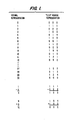
- Fig. 1 gives examples of residue arithmetic in a "235" representation where 2 is the prime number associated with the leftmost radix, 3 with the central radix, and 5 with the rightmost radix.
- Collins, et al. use controlled diffraction gratings produced by interfering light from two single mode optical fibers to implement residue addition.
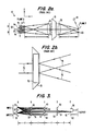
- FIG. 2a Collins et al, show a system, designated generally by reference numeral 10, that is provided with numerical information through two groups A & B of optical fibers 11 with the fiber ends acting as point sources in the input plane Q.
- the central two fibers 11a and 11b represent zero in each group A & B, respectively.
- Numerical values for input A increase in one direction from the central axis 20 (positive y direction) while numerical values for input B increase in the opposite direction.
- the light valve may, for example, be the Hughes liquid crystal light valve more particularly described in W.P. Bleha et al "Application of the Liquid Crystal Light Valve to Real-Time Optical Data Processing," Opt. Eng. , 17 , p. 371.
- the control area 70 serves as an active area.
- An incident write beam 72 strikes a photosensitive CdS film (not shown) on the input side of the light valve 15.
- the CdS film allows the intensity of the write beam 72 to control the field produced across the liquid crystal layer. This in turn effects a change in the orientation of the liquid crystal molecules and hence provides control over their birefringence. This control is available at each of 600 x 600 image elements of the device simultaneously and independently.
- a polarized read beam 74 incident on the output side of light valve 15 is reflected by a dielectric mirror behind the liquid crystal layer. The intensity of the reflected beam 76 is thus controlled by the intensity of write beam 72 at any particular image element.
- the interference pattern fringe spacing is a function of the distance between the illuminated fibers which, in terms of quantized units of fiber separation, is proportional to the sum of the two numbers represented by the corresponding fibers.
- the distance between a fiber 11c representing the number 4 in Group A (four units from the 0 in Group A) and a fiber 11d representing the number 3 in Group B (three units from the 0 in Group B) is 8 units, seven units from the sum of 4 and 3, plus one unit representing the separation between the two 0's at 11a and 11b.
- light incident from a source 19 is directed toward the light valve via lens 25 to form the read beam 74 of Fig. 2b.
- This read beam is subsequently reflected by the dielectric mirror in light valve 15 and diffracted by the gratings resulting from the incident interference pattern on the light valve input side.
- the reflected and diffracted light is then focused through Fourier transform lens 25 onto Plane P into various diffracted orders of which only the +1 order is retained.
- the deflected distance from the z axis (i.e., along the y axis) of the diffracted spot 23 is proportional to the separation of the fibers 11 in the input plane. For example, the addition of two 0 inputs gives an output deflection of one unit.
- the deflected distance past this unit offset is equal to the sum of the two numbers represented by the fibers producing the initial diffraction grating, thereby yielding the result of residue operation.
- mutually coherent light sources forming two separate channels of a parallel optical processor are arranged along a line and separated from each other by a predetermined distance.
- a first group of lenses in the same focal plane are placed one focal length away from the light sources.
- Fourier transform filters in the same focal plane are placed one focal length away from the first group of lenses.
- a second group of lenses in the same focal plane are placed one focal length away from the Fourier transform filters.
- a group of collectors in the same focal plane are placed one focal length away from the second group of lenses.
- One light source from each channel is turned on, thereby forming a spatial pattern which is presented to a multiple channel optical system comprising the first group of lenses, the Fourier transform filters and the second group of lenses.
- the optical system allows light energy from the two channels of light sources to emerge from only one of its channels. This one channel is received by a corresponding collector and is indicative of the desired output state.
- Fig. 3 the basic operation of the invention can most easily be illustrated in its AND logic unit form.
- Four mutually coherent point sources 20-23 that can be individually turned on or off are provided in a spaced relationship along a plane A.
- Source 20 is the “true” source and source 21 is the “false” source thereby forming Input I.
- Source 22 is the “false” source and source 23 is the “true” source of Input II.
- the sources 20-23 are arranged along a line and separated by equal distances d.
- Lens 30-32 are placed along the same focal plane B one focal length f away from the sources 20-23 to produce Fourier transforms of the source configuration generated when one of the sources is turned on from each of Input I and Input II.
- the Fourier transforms are produced along focal Plane C one focal length away from lenses 30-32 where Fourier transform filters 40-42 are located. It is a well-known property of the Fourier transform that, apart from an overall phase, the transform depends only on the structure of the pattern, not its absolute location. Thus, sources a distance 2d apart will produce the same transform, whether the sources 20 and 22 are on, or sources 21 and 23 are on.
- Fig. 4 shows the four possible input patterns, the spacing between sources for each of the patterns and the desired output state.
- light from source 20 of Input I and source 22 of Input II passes with highest transmission through the filter 41 labeled "2d” as the sources 20 and 22 are a distance “2d” apart.
- This energy is collected by the lenses 50 to 52 in the lens array along focal plane D located one focal length away from filters 40 to 42.
- the energy allowed to pass through lenses 50-52 is then focused onto light collectors 60 to 62 (e.g., square law devices) located in Plane E one focal length away from lenses 50 to 52.
- the maximum intensity, by at least a two-to-one margin, will fall on collector 61.
- Thresholding (not shown) will then allow energy to pass through only one channel, the one corresponding to the correct answer.
- the collector 61 behind the "2d” filter 41, is connected to designate a "false” output.
- a "true-false” input i.e., source 20 and 22 on
- results in a “false” output as required by the truth table in Fig. 4.
- the filter 41 passes light resulting from the other possible “2d” configuration in which only sources 21 and 23 are on, corresponding to a "false-true” input condition.
- a "false” output designation likewise results from collector 61.
- the "1d" channel passing through filter 40 and lens 50 leads to a "false” output.
- collector 62 designating a "true” output.
- the collectors 60 to 62 in Plane E can be either detectors if an electronic output is desired, or optical non-linear devices (e.g., optical bistable switches) for an optical output.
- an optical light valve is not required for the invention to perform its function.
- the invention may be extended to take the form of a fully parallel adder by combining the same type of hardware used in the AND unit with the concept of residue arithmetic.
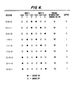
- the adder 100 for radix 3 is shown in Fig. 5, and incorporates the input/output relationships shown in Fig. 6.
- focal length f is 200 mm and the distance d between point sources is 125 microns.
- point sources 120-122 make up one channel labeled "Input I" while sources 123-125 make up the second channel “Input II”.
- Lenses 130-134 lie along focal plane B one focal length f away from the sources positional in plane A.
- Fourier filters 140-144 lie along focal plane C one focal length away from lenses 130-134 in plane B.
- Lenses 150-154 lie along focal plane D one focal length away from filters 140-144.
- Detectors 160-164 lie along focal plane E one focal length away from lenses 150-154.
- the geometric relationship between the inputs and the addition result can be generalized as follows.
- the addition of any two numbers in the radix, n1 from input I and n2 from input II, is related to the spacing between the two sources in the input pattern indicative of n1 and n2.
- (n1 + n2) modulo p, where p is the radix corresponds to the spacing between n1 and n2 according to the relationship (n1+n2+1)d.
- the radix p adder requires 2p -1 linear optical elements in each focal plane B, C, and D.
- the invention can also take the form of a multiplier.
- this form exploits the property of residue arithmetic that the nonzero numbers in radix p, where p is a prime number, form a closed set under the multiplication operation.
- an N x N multiplication table has only N entries, rather than N2 as in ordinary multiplication, so that only order N, rather than N2, filters are required for selection of the appropriate final state.
- the implementation of this relationship is basically the same as the adder of Fig. 5.
- the order of the input numbers is permuted as is discussed by Szabo, N.S., and R.I. Tanaka, Residue Arithmetic and its Applications to Computer Technology , McGraw-Hill, New York, 1977, incorporated herein by reference.
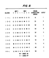
- the input/output table for a radix 5 multiplier is shown in Fig. 8 and the device which incorporates these relationships is shown in Fig. 7, where the reference letters d, f and A-E refer to the same items as in Fig. 3 and Fig. 5. Note that the only additional complications of the multiplier over that of the adder are that a separate channel must be included that allows light from zero entries to pass directly to the output and that a filter must discriminate against a single input, i.e., a nonzero number multiplied by zero, as well as incorrect spacing.
- the geometrical relationship between the inputs and the multiplication result can be generalized as follows.
- the multiplication of any two numbers in the permuted input order, x n 1 from input I and x n 2, from input II, is related to the spacing between the two sources in the input pattern indicative of x n 1 and x n 2.
- (x n 1 x x n 2) modulo p corresponds to the spacing between x n 1 and x n 2 according to the relationship (n1 + n2 + 1)d.
- a radix p multiplier requires 2p - 3 linear optical elements in each plane B, C and D.
- the present invention can likewise be extended to perform residue subtraction.
- the lenses in plane B might alternatively be replaced with a single spherical lens.
- the lenses in plane D might alternatively be replaced by a single cylindrical lens.
- the invention has been described with reference to only two channels of light sources. However, the present invention could be extended for applications requiring three or more channels.
- the present invention achieves high-speed parallel optical arithmetic and logic operations without the use of slow optical light valves.
- the configuration of linear optical elements provides a novel high-speed parallel optical architecture.
Landscapes
- Engineering & Computer Science (AREA)
- Theoretical Computer Science (AREA)
- Physics & Mathematics (AREA)
- General Physics & Mathematics (AREA)
- Computing Systems (AREA)
- Mathematical Analysis (AREA)
- Computational Mathematics (AREA)
- Mathematical Optimization (AREA)
- Pure & Applied Mathematics (AREA)
- Mathematical Physics (AREA)
- General Engineering & Computer Science (AREA)
- Image Analysis (AREA)
- Image Processing (AREA)
Applications Claiming Priority (2)
| Application Number | Priority Date | Filing Date | Title |
|---|---|---|---|
| US07/019,767 US4797843A (en) | 1987-02-27 | 1987-02-27 | Parallel optical arithmetic/logic unit |
| US19767 | 1987-02-27 |
Publications (2)
| Publication Number | Publication Date |
|---|---|
| EP0282794A2 true EP0282794A2 (fr) | 1988-09-21 |
| EP0282794A3 EP0282794A3 (fr) | 1991-04-03 |
Family
ID=21794928
Family Applications (1)
| Application Number | Title | Priority Date | Filing Date |
|---|---|---|---|
| EP19880102936 Withdrawn EP0282794A3 (fr) | 1987-02-27 | 1988-02-26 | Unité arithmétique-logique optique parallèle |
Country Status (6)
| Country | Link |
|---|---|
| US (1) | US4797843A (fr) |
| EP (1) | EP0282794A3 (fr) |
| JP (1) | JPS63229437A (fr) |
| KR (1) | KR880010361A (fr) |
| AU (1) | AU1060588A (fr) |
| CA (1) | CA1284188C (fr) |
Cited By (2)
| Publication number | Priority date | Publication date | Assignee | Title |
|---|---|---|---|---|
| EP0378833A1 (fr) * | 1988-12-21 | 1990-07-25 | The Boeing Company | Méthode et appareil pour effectuer une comparaison arithmétique-optique à entrées multiples |
| US5191549A (en) * | 1988-12-21 | 1993-03-02 | The Boeing Company | Method and apparatus for performing a multiple-input optical arithmetic comparison |
Families Citing this family (16)
| Publication number | Priority date | Publication date | Assignee | Title |
|---|---|---|---|---|
| US4939682A (en) * | 1988-07-15 | 1990-07-03 | The Boeing Company | Integrated electro-optic arithmetic/logic unit and method for making the same |
| US4910699A (en) * | 1988-08-18 | 1990-03-20 | The Boeing Company | Optical computer including parallel residue to binary conversion |
| US4918635A (en) * | 1988-11-15 | 1990-04-17 | Yao Li | Ultrafast digital photonic signal processing using optical noncollinear second harmonic generation |
| US4999486A (en) * | 1989-09-29 | 1991-03-12 | The Boeing Company | Optoelectric logic array |
| US5050120A (en) * | 1989-09-29 | 1991-09-17 | The Boeing Company | Residue addition overflow detection processor |
| US4996527A (en) * | 1989-09-29 | 1991-02-26 | The Boeing Company | Pipelined residue to mixed base converter and base extension processor |
| US5249144A (en) * | 1989-09-29 | 1993-09-28 | The Boeing Company | Programmable optical arithmetic/logic unit |
| US4964687A (en) * | 1989-09-29 | 1990-10-23 | The Boeing Company | Optical latch and method of latching data using same |
| US5077793A (en) * | 1989-09-29 | 1991-12-31 | The Boeing Company | Residue number encryption and decryption system |
| US5045681A (en) * | 1989-09-29 | 1991-09-03 | The Boeing Company | Optoelectric ripple carry adder |
| US4963869A (en) * | 1989-09-29 | 1990-10-16 | The Boeing Company | Parallel residue to mixed base converter |
| US5107451A (en) * | 1990-01-30 | 1992-04-21 | The Boeing Company | Method and apparatus for pipelined detection of overflow in residue arithmetic multiplication |
| US5050117A (en) * | 1990-02-06 | 1991-09-17 | Wright State University | Spatial light rebroadcaster optical computing cells |
| US5033016A (en) * | 1990-03-06 | 1991-07-16 | The Boeing Company | Coherence multiplexed arithmetic/logic unit |
| WO2015157574A2 (fr) * | 2014-04-11 | 2015-10-15 | Lockheed Martin Corporation | Système et procédé de mesure de puissance optique sans contact |
| CN107179612B (zh) * | 2017-05-26 | 2023-06-30 | 华侨大学 | 一种新型无串扰和无分辨率损失的自由3d显示器 |
Family Cites Families (6)
| Publication number | Priority date | Publication date | Assignee | Title |
|---|---|---|---|---|
| BE552987A (fr) * | 1955-12-07 | |||
| US3614192A (en) * | 1969-12-18 | 1971-10-19 | Perkin Elmer Corp | Holographic logic operator for an optical data processing system |
| US3903400A (en) * | 1973-11-14 | 1975-09-02 | Itek Corp | Parallel digital data processing system |
| US4088964A (en) * | 1975-01-22 | 1978-05-09 | Clow Richard G | Multi-mode threshold laser |
| US4042814A (en) * | 1976-06-28 | 1977-08-16 | The United States Of America As Represented By The Secretary Of The Navy | Electro-optic binary adder |
| US4351589A (en) * | 1980-04-08 | 1982-09-28 | Hughes Aircraft Company | Method and apparatus for optical computing and logic processing by mapping of input optical intensity into position of an optical image |
-
1987
- 1987-02-27 US US07/019,767 patent/US4797843A/en not_active Expired - Fee Related
-
1988
- 1988-01-20 AU AU10605/88A patent/AU1060588A/en not_active Abandoned
- 1988-02-25 JP JP63040919A patent/JPS63229437A/ja active Pending
- 1988-02-26 CA CA000560025A patent/CA1284188C/fr not_active Expired - Lifetime
- 1988-02-26 EP EP19880102936 patent/EP0282794A3/fr not_active Withdrawn
- 1988-02-27 KR KR1019880002042A patent/KR880010361A/ko not_active Withdrawn
Cited By (2)
| Publication number | Priority date | Publication date | Assignee | Title |
|---|---|---|---|---|
| EP0378833A1 (fr) * | 1988-12-21 | 1990-07-25 | The Boeing Company | Méthode et appareil pour effectuer une comparaison arithmétique-optique à entrées multiples |
| US5191549A (en) * | 1988-12-21 | 1993-03-02 | The Boeing Company | Method and apparatus for performing a multiple-input optical arithmetic comparison |
Also Published As
| Publication number | Publication date |
|---|---|
| US4797843A (en) | 1989-01-10 |
| AU1060588A (en) | 1988-09-01 |
| EP0282794A3 (fr) | 1991-04-03 |
| KR880010361A (ko) | 1988-10-08 |
| CA1284188C (fr) | 1991-05-14 |
| JPS63229437A (ja) | 1988-09-26 |
Similar Documents
| Publication | Publication Date | Title |
|---|---|---|
| US4797843A (en) | Parallel optical arithmetic/logic unit | |
| US5784309A (en) | Optical vector multiplier for neural networks | |
| Tanida et al. | Optical logic array processor using shadowgrams | |
| Caulfield | Optical neural networks | |
| US4318581A (en) | Optical holographic content-addressable memory system for truth table look-up processing | |
| JPH07104880A (ja) | 光電子記憶処理装置および光学式修正符号付きディジット算術演算実行方法 | |
| EP0229177B1 (fr) | Agencement de permutation optique | |
| Gaylord et al. | Optical digital truth table look-up processing | |
| Li et al. | Content-addressable-memory-based single-stage optical modified-signed-digit arithmetic | |
| US4824192A (en) | Optical processing | |
| US4595994A (en) | Optical engagement array multiplication | |
| Lohman et al. | Optical interconnection network utilizing diffraction gratings | |
| US3614191A (en) | Associative memory employing holography | |
| US3466433A (en) | Optical parallel adder | |
| KR102829671B1 (ko) | 광전자 모듈의 클러스터링을 통한 광 신경망의 구현 방법 및 클러스터링된 광전자 모듈을 통한 광신경망 장치 | |
| US3644889A (en) | Symbol recognition system particularly for alphanumeric characters utilizing electro-optical techniques with noncoherent light | |
| Viénot et al. | Three methods of information assessment for optical data processing | |
| US3553460A (en) | Realization of combinatorial functions by utilizing optical holography and phase modulation by input information | |
| US3592547A (en) | Optical matrix-processing system and optics | |
| US3743422A (en) | Optical image processor | |
| US5770854A (en) | Pattern-recognition computing and method for producing same | |
| Guest et al. | Two proposed holographic numerical optical processors | |
| Davis et al. | Multichannel optical correlator/convolver utilizing the magnetooptic spatial light modulator | |
| AU701008B2 (en) | Pattern-recognition computing and method for producing same | |
| Preston Jr | Digital holographic logic |
Legal Events
| Date | Code | Title | Description |
|---|---|---|---|
| PUAI | Public reference made under article 153(3) epc to a published international application that has entered the european phase |
Free format text: ORIGINAL CODE: 0009012 |
|
| AK | Designated contracting states |
Kind code of ref document: A2 Designated state(s): DE FR GB SE |
|
| PUAL | Search report despatched |
Free format text: ORIGINAL CODE: 0009013 |
|
| AK | Designated contracting states |
Kind code of ref document: A3 Designated state(s): DE FR GB SE |
|
| RHK1 | Main classification (correction) |
Ipc: G06F 7/56 |
|
| STAA | Information on the status of an ep patent application or granted ep patent |
Free format text: STATUS: THE APPLICATION IS DEEMED TO BE WITHDRAWN |
|
| 18D | Application deemed to be withdrawn |
Effective date: 19911004 |