EP0282806B1 - Système de commande d'un appareil hydraulique, en particulier une grue de chargement - Google Patents
Système de commande d'un appareil hydraulique, en particulier une grue de chargement Download PDFInfo
- Publication number
- EP0282806B1 EP0282806B1 EP19880103064 EP88103064A EP0282806B1 EP 0282806 B1 EP0282806 B1 EP 0282806B1 EP 19880103064 EP19880103064 EP 19880103064 EP 88103064 A EP88103064 A EP 88103064A EP 0282806 B1 EP0282806 B1 EP 0282806B1
- Authority
- EP
- European Patent Office
- Prior art keywords
- valve
- lever
- control lever
- hand
- control
- Prior art date
- Legal status (The legal status is an assumption and is not a legal conclusion. Google has not performed a legal analysis and makes no representation as to the accuracy of the status listed.)
- Expired - Lifetime
Links
- 230000007935 neutral effect Effects 0.000 claims description 7
- 230000001681 protective effect Effects 0.000 description 3
- 238000010276 construction Methods 0.000 description 1
- 238000011109 contamination Methods 0.000 description 1
- 230000001960 triggered effect Effects 0.000 description 1
Images


Classifications
-
- B—PERFORMING OPERATIONS; TRANSPORTING
- B66—HOISTING; LIFTING; HAULING
- B66C—CRANES; LOAD-ENGAGING ELEMENTS OR DEVICES FOR CRANES, CAPSTANS, WINCHES, OR TACKLES
- B66C23/00—Cranes comprising essentially a beam, boom, or triangular structure acting as a cantilever and mounted for translatory of swinging movements in vertical or horizontal planes or a combination of such movements, e.g. jib-cranes, derricks, tower cranes
- B66C23/88—Safety gear
- B66C23/90—Devices for indicating or limiting lifting moment
Definitions
- the invention relates to a device for controlling a hydraulically operated device, in particular a loading crane, with at least one control unit which has a control valve, the valve piston of which can be deflected in at least one control lever in two opposite directions from a neutral position against spring force in order to move to activate the device with a protective device which, when a limit value of the operating state occurs, releases a catch arranged in the linkage connecting the control lever and the valve piston in the direction causing the limit value of the operating state to be exceeded, and thus the return of the valve piston to the spring force in allows neutral position while maintaining the positive connection in the opposite direction.
- the known devices have two disadvantages in particular.
- On the one hand there are considerable constructional difficulties: in particular in the case of mobile devices such as mobile cranes, the space for accommodating additional facilities is generally limited.
- the axial extent of the housing containing the latching is not insignificant and the arrangement coaxial with the valve piston results in a considerable overall length.
- the problem is usually exacerbated by the fact that a linkage is often connected to the control lever, which leads to the other side of the vehicle in order to be able to optionally control the movements from there.
- a second problem arises from the fact that in the known devices the valve stroke and the stroke of the latching have to be the same size.
- the valve stroke is usually only a few millimeters.
- a matching latching would therefore have to be produced with a high degree of accuracy and moreover be well sealed against external influences, in particular contamination, which leads to an increase in price. Flawless functioning is only conceivable if the control valve and latching are assembled into one unit; in general, however, it is desirable to use different valves with a standard locking, or vice versa. As a rule, several control valves are housed in a single block, in which case only individual hydraulic circuits require protection. However, if the latching is now arranged separately from the valve, the short valve paths make it difficult to adjust the latching.
- the disadvantages mentioned are avoided in that the protective device is put into operation when a limit value of the overload occurs, and in that part of the linkage is a valve lever which is pivotally mounted about a fixed pivot point and which is articulated on the one hand on the valve piston and on the other hand with the control lever and interposition of the latching which can be triggered by the protective device is connected.
- swivel arm 12 which can be raised or lowered by means of a hydraulic drive 13 consisting of cylinder and piston with piston rod. It is easy to see that the load moment is reduced or increased by this lifting and lowering movement.
- the cylinder space 13 ′′ of the hydraulic drive 13 assigned to the lowering movement is connected via a lowering line 17 to a control valve 14.
- the cylinder space 13 ′ communicates via a line 18 with an overload valve 22.
- This overload valve is prestressed into the closed position by means of a spring and has one of the Spring force acts on counteracting control piston, which communicates with line 18 via line 20.
- the overload valve 22 responds in a known manner, i.e. it connects the line 18 to the line 23 and thus actuates a locking drive 15.
- This locking drive 15 indirectly brings all the control valves 14 into a neutral position, which hydraulic drives are assigned, which can cause a movement that increases the load moment.
- the locking drive 15 lifts the positive connection between the control lever 2 and the valve piston 1 in one direction of movement.
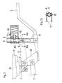
- valve piston 1 of the control valve 14 is coupled to the control lever 2 via a valve lever 4.
- Both the valve lever 4 and the control lever 2 can be pivoted about a pivot axis 5 which is fixedly arranged on the housing 6 of the valve 14.
- the control lever 2 is connected by a tab 21 to the pivot axis 5, which makes it possible to actuate the control lever 2 directly via its handle or via the linkage 7.
- This linkage 7 leads in a known manner to a pivotable handle arranged on the opposite side of the vehicle.
- a sleeve 8 is arranged, which is fixedly connected to the hydraulically operated locking drive 15.
- the valve lever 4 is connected via a linkage 10 to a pin 9 which is mounted in the sleeve 8.
- the locking drive 15 forms together with an annular groove 30 on the pin 9 a locking 3, which is released by overpressure in the hydraulic system.
- the articulation 10 of the valve lever 4 is displaceable in the slot 11 of the sleeve 8. This means that the valve lever 4 can return to its neutral position, even if the control lever 2 is deflected upwards.
- the valve lever 4 can continue to be pivoted by means of the control lever 2 in the sense of inserting the valve piston 1 as soon as, as shown in FIG. 2, the linkage 10 strikes the upper edge of the elongated hole 11.
- the embodiment according to FIG. 3 differs from that according to FIG. 2 initially in that the latching is formed by two pairs of stops 24, 31 and 24 ', 31', respectively, where a pair of stops can be disengaged .
- This makes it possible either to make the upward movement or the downward movement of the control lever 2 ineffective, which is necessary if it is not certain from the outset which type of pivoting of the control lever leads to an increase in the load torque.
- valve lever in the embodiment according to FIG. 3 consists of two parts 4, 4 'connected by screws 29 is only a constructive detail. It appears more important to note that the actuation of the stops 31, 31 'here does not take place hydraulically, as in the exemplary embodiment according to FIG. 2, but instead by servomotors 27, 27', which by means of lines 26, 26 'with a sensor for the occurrence of Overload are connected.
- the servomotors 27, 27 ' are expediently switched such that, in the event of a power failure, actuation of the valve lever 4 by the control lever 2 is not possible.
- Stops 32, 32 ' can prevent the control lever 2 from pivoting so far relative to the valve lever 4 that one of the stops 31, 31' comes into engagement with the wrong stop 32, 32 'when it is switched on again.
- the control lever 2 can also be preloaded towards its neutral position by a relatively weak spring.
Landscapes
- Engineering & Computer Science (AREA)
- Mechanical Engineering (AREA)
- Control And Safety Of Cranes (AREA)
- Mechanical Control Devices (AREA)
Claims (6)
Applications Claiming Priority (2)
| Application Number | Priority Date | Filing Date | Title |
|---|---|---|---|
| AT45287A AT388359B (de) | 1987-03-02 | 1987-03-02 | Einrichtung zur steuerung eines hydraulisch betaetigten geraetes, insbesondere eines ladekrans |
| AT452/87 | 1987-03-02 |
Publications (2)
| Publication Number | Publication Date |
|---|---|
| EP0282806A1 EP0282806A1 (fr) | 1988-09-21 |
| EP0282806B1 true EP0282806B1 (fr) | 1990-05-30 |
Family
ID=3490996
Family Applications (1)
| Application Number | Title | Priority Date | Filing Date |
|---|---|---|---|
| EP19880103064 Expired - Lifetime EP0282806B1 (fr) | 1987-03-02 | 1988-03-01 | Système de commande d'un appareil hydraulique, en particulier une grue de chargement |
Country Status (3)
| Country | Link |
|---|---|
| EP (1) | EP0282806B1 (fr) |
| AT (1) | AT388359B (fr) |
| DE (1) | DE3860184D1 (fr) |
Families Citing this family (2)
| Publication number | Priority date | Publication date | Assignee | Title |
|---|---|---|---|---|
| CN102069783B (zh) * | 2010-12-31 | 2012-08-15 | 徐州重型机械有限公司 | 汽车起重机及其支腿操纵装置 |
| WO2016181141A2 (fr) | 2015-05-11 | 2016-11-17 | The Queen Elizabeth Hospital King's Lynn Nhs Foundation Trust | Système d'avertissement de sécurité |
Family Cites Families (9)
| Publication number | Priority date | Publication date | Assignee | Title |
|---|---|---|---|---|
| DE1276307B (de) * | 1966-10-01 | 1968-08-29 | Miag Muehlenbau & Ind Gmbh | Einrichtung zur selbsttaetigen Begrenzung des Lastmomentes bei Auslegerkranen mit hydraulischem Antrieb |
| US3645407A (en) * | 1970-06-15 | 1972-02-29 | Daniel F Przybylski | Overload protector for crane booms |
| US3792780A (en) * | 1971-12-02 | 1974-02-19 | Kidde & Co Walter | Mechanism for positioning and restricting crane control levers to prevent dangerous load condition |
| DE2344168C3 (de) * | 1973-09-01 | 1979-08-02 | Krueger & Co Kg, 4300 Essen | Einrichtung zur Sicherung eines Kranbetätigungsgestänges bei Überschreiten eines vorgegebenen maximalen Lastmomentes |
| DE2501753C3 (de) * | 1975-01-17 | 1979-05-23 | Kittel, Artur, 8034 Neugermering | Einrichtung zur wahlweisen Fern- und Nahsteuerung für hydraulisch betätigte Kräne |
| US4119118A (en) * | 1977-01-13 | 1978-10-10 | Walter Kidde & Company, Inc. | Automatic machine motion restricting mechanism |
| US4170308A (en) * | 1977-11-01 | 1979-10-09 | Koehring Company | Hydraulic function disconnect means |
| US4411368A (en) * | 1980-03-21 | 1983-10-25 | Roger Manjot | Safety system for hydraulically controlled hoisting apparatus |
| US4422619A (en) * | 1981-07-21 | 1983-12-27 | Griffiths Edward E | Remote valve operating system |
-
1987
- 1987-03-02 AT AT45287A patent/AT388359B/de not_active IP Right Cessation
-
1988
- 1988-03-01 EP EP19880103064 patent/EP0282806B1/fr not_active Expired - Lifetime
- 1988-03-01 DE DE8888103064T patent/DE3860184D1/de not_active Expired - Lifetime
Also Published As
| Publication number | Publication date |
|---|---|
| EP0282806A1 (fr) | 1988-09-21 |
| ATA45287A (de) | 1988-11-15 |
| AT388359B (de) | 1989-06-12 |
| DE3860184D1 (de) | 1990-07-05 |
Similar Documents
| Publication | Publication Date | Title |
|---|---|---|
| DE3026273A1 (de) | Fernbedienter manipulator | |
| DE3628424A1 (de) | Querleitungs-entlastungsventilmechanismus | |
| DE2360343C3 (de) | Frachthalte- und Freigabevorrichtung | |
| DE2616860A1 (de) | Ueberlastschutz fuer kranausleger | |
| DE3685681T2 (de) | Lasthebevorrichtung. | |
| EP0149453A2 (fr) | Attelage pour remorque | |
| DE1630683B2 (de) | Betätigungsvorrichtung fur die Fahrtrichtung und Fahrgeschwindigkeit des Antriebs eines Fahrzeugs | |
| EP0282806B1 (fr) | Système de commande d'un appareil hydraulique, en particulier une grue de chargement | |
| DE69205209T2 (de) | Mähmaschine. | |
| DE2713838A1 (de) | Hydrauliksystem | |
| DE3879088T2 (de) | Kupplungsstange mit kontakt fuer die steuerung des fluges eines luftfahrzeuges. | |
| DE2825178C2 (de) | Steuerungsvorrichtung zum Betätigen eines Druck-Zugkabels | |
| DE1457718B1 (de) | Vorrichtung zur automatischen Steuerung des hydraulischen Systems eines Ackerschleppers mit Kraftheber | |
| DE1123021B (de) | Schwenkeinrichtung zur Betaetigung eines elektrischen Endschalters | |
| DE1555648B2 (de) | Ausloeseeinrichtung fuer die verriegelung einer einstellbaren lenksaeule eines kraftfahrzeugs | |
| DE2202006A1 (de) | Stellvorrichtung fuer ein Schiffsruderblatt | |
| DE3446918C2 (fr) | ||
| DE3045568C2 (de) | Motorantrieb für Niederspannungs-Schutzschalter | |
| DE2646294C2 (de) | Hydraulische Antriebsvorrichtung für einen Aufzug | |
| DE2106195C2 (de) | Verteileranordnung für unter Druck stehendes Strömungsmittel mit zwei Verteilern | |
| DE19714069C2 (de) | Kraftfahrzeugtürverschluß | |
| DE320998C (de) | Stellvorrichtung fuer Eisenbahnweichen | |
| DE10144501A1 (de) | Hubarbeitsbühne mit Hydraulik-Steuerung | |
| EP0158738A2 (fr) | Dispositif hydraulique de protection contre les surcharges pour une grue de chargement | |
| DE2102612A1 (de) | Lasthebevorrichtung, insbesondere Ladekran |
Legal Events
| Date | Code | Title | Description |
|---|---|---|---|
| PUAI | Public reference made under article 153(3) epc to a published international application that has entered the european phase |
Free format text: ORIGINAL CODE: 0009012 |
|
| AK | Designated contracting states |
Kind code of ref document: A1 Designated state(s): DE FR IT SE |
|
| 17P | Request for examination filed |
Effective date: 19880929 |
|
| 17Q | First examination report despatched |
Effective date: 19890519 |
|
| GRAA | (expected) grant |
Free format text: ORIGINAL CODE: 0009210 |
|
| AK | Designated contracting states |
Kind code of ref document: B1 Designated state(s): DE FR IT SE |
|
| PG25 | Lapsed in a contracting state [announced via postgrant information from national office to epo] |
Ref country code: IT Free format text: LAPSE BECAUSE OF FAILURE TO SUBMIT A TRANSLATION OF THE DESCRIPTION OR TO PAY THE FEE WITHIN THE PRE;WARNING: LAPSES OF ITALIAN PATENTS WITH EFFECTIVE DATE BEFORE 2007 MAY HAVE OCCURRED AT ANY TIME BEFORE 2007. THE CORRECT EFFECTIVE DATE MAY BE DIFFERENT FROM THE ONE RECORDED.SCRIBED TIME-LIMIT Effective date: 19900530 Ref country code: FR Effective date: 19900530 Ref country code: SE Effective date: 19900530 |
|
| REF | Corresponds to: |
Ref document number: 3860184 Country of ref document: DE Date of ref document: 19900705 |
|
| EN | Fr: translation not filed | ||
| PLBE | No opposition filed within time limit |
Free format text: ORIGINAL CODE: 0009261 |
|
| STAA | Information on the status of an ep patent application or granted ep patent |
Free format text: STATUS: NO OPPOSITION FILED WITHIN TIME LIMIT |
|
| 26N | No opposition filed | ||
| PG25 | Lapsed in a contracting state [announced via postgrant information from national office to epo] |
Ref country code: DE Effective date: 19920101 |