EP0283058B1 - Verfahren und Vorrichtung zur Unterdrückung der kohärenten Interferenzeffekte von kernmagnetischen Resonanzsignalen - Google Patents
Verfahren und Vorrichtung zur Unterdrückung der kohärenten Interferenzeffekte von kernmagnetischen Resonanzsignalen Download PDFInfo
- Publication number
- EP0283058B1 EP0283058B1 EP88200145A EP88200145A EP0283058B1 EP 0283058 B1 EP0283058 B1 EP 0283058B1 EP 88200145 A EP88200145 A EP 88200145A EP 88200145 A EP88200145 A EP 88200145A EP 0283058 B1 EP0283058 B1 EP 0283058B1
- Authority
- EP
- European Patent Office
- Prior art keywords
- reference signal
- phase
- magnetic field
- resonance signals
- signal
- Prior art date
- Legal status (The legal status is an assumption and is not a legal conclusion. Google has not performed a legal analysis and makes no representation as to the accuracy of the status listed.)
- Expired
Links
- 238000000034 method Methods 0.000 title claims description 24
- 230000001427 coherent effect Effects 0.000 title claims description 13
- 230000000694 effects Effects 0.000 title description 15
- 230000005415 magnetization Effects 0.000 claims description 25
- 238000009826 distribution Methods 0.000 claims description 21
- 230000009466 transformation Effects 0.000 claims description 8
- 230000005540 biological transmission Effects 0.000 claims description 2
- 230000009897 systematic effect Effects 0.000 claims description 2
- 238000005481 NMR spectroscopy Methods 0.000 description 16
- 230000033001 locomotion Effects 0.000 description 5
- 238000001228 spectrum Methods 0.000 description 5
- 230000005284 excitation Effects 0.000 description 4
- 230000010363 phase shift Effects 0.000 description 4
- 238000002360 preparation method Methods 0.000 description 4
- 238000000264 spin echo pulse sequence Methods 0.000 description 4
- 230000015572 biosynthetic process Effects 0.000 description 2
- 230000001419 dependent effect Effects 0.000 description 2
- 230000010358 mechanical oscillation Effects 0.000 description 2
- 238000005070 sampling Methods 0.000 description 2
- 238000004611 spectroscopical analysis Methods 0.000 description 2
- 238000001514 detection method Methods 0.000 description 1
- 238000005259 measurement Methods 0.000 description 1
- 230000002503 metabolic effect Effects 0.000 description 1
- 238000000655 nuclear magnetic resonance spectrum Methods 0.000 description 1
- 230000000737 periodic effect Effects 0.000 description 1
- 230000010287 polarization Effects 0.000 description 1
- 238000011896 sensitive detection Methods 0.000 description 1
Images

Classifications
-
- G—PHYSICS
- G01—MEASURING; TESTING
- G01R—MEASURING ELECTRIC VARIABLES; MEASURING MAGNETIC VARIABLES
- G01R33/00—Arrangements or instruments for measuring magnetic variables
- G01R33/20—Arrangements or instruments for measuring magnetic variables involving magnetic resonance
- G01R33/44—Arrangements or instruments for measuring magnetic variables involving magnetic resonance using nuclear magnetic resonance [NMR]
- G01R33/48—NMR imaging systems
- G01R33/54—Signal processing systems, e.g. using pulse sequences ; Generation or control of pulse sequences; Operator console
- G01R33/56—Image enhancement or correction, e.g. subtraction or averaging techniques, e.g. improvement of signal-to-noise ratio and resolution
- G01R33/565—Correction of image distortions, e.g. due to magnetic field inhomogeneities
Definitions
- the invention relates to a method of determining the nuclear magnetization distribution from magnetic resonance signals which are produced in sequences in a body located in a steady magnetic field, a sequence comprising at least one high-frequency electromagnetic pulse produced by means of a reference signal, after which the magnetic resonance signal produced is detected in the presence of the reference signal, and the nuclear magnetization distribution is determined from the detected resonance signals by means of a Fourier transformation.
- the invention further relates to an apparatus for determining a nuclear magnetization distribution in a part of a body, the apparatus comprising means for producing a steady magnetic field, means for producing magnetic field gradients and means for producing a reference signal, as well as transmitter means for transmitting a high-frequency electromagnetic pulse formed in the transmitter means by means of the reference signal and receiver means for receiving and detecting by means of the reference signal a resonance signal which is produced by at least one high-frequency electromagnetic pulse in the body, and processing means for processing the detected resonance signals.
- nuclear magnetization distribution is to be interpreted in a wide sense, while inter alia terms like “spin nuclei density distribution”, “longitudinal relaxiation time (T1) distribution”, “transversal relaxiation time (T2) distribution” and “nuclear magnetic resonance frequency spectrum distribution” (NMR position-dependent spectroscopy) are to be understood to be included in the term” nuclear magnetization distribution.”
- the small excess is to be interpreted, considered macroscopically, as a magnetization M of the body or as a small polarization of the spin nuclei present in the body.
- the magnetization M After irradiation of the body arranged in the magnetic field by a high-frequency electromagnetic pulse, which should have a given frequency, the magnetization M is unbalanced and will perform a precessional motion about the direction of the magnetic field B O .
- the magnetization M is to be interpreted as a vector, which due to the irradiation moves in a plane at right angles to the direction of irradiation.
- the component of the magnetization M at right angles to the z axis i.e. the so-called transversel magnetization, has the result that after irradiation a resonance signal is obtained.
- the high-frequency electromagnetic pulses are formed by transmitter apparatus in which the pulse is produced by modulation of a reference signal which is supplied by an oscillator and has a frequency (in the proximity of) ⁇ O with a low-frequency signal determining the pulse shape, after which the pulse is transmitted by the transmitter apparatus by means of a transmitter coil located near the body.
- the magnitude of the transverse magnetization is determined by the surface area below the pulse.
- a 90° pulse is concerned when the magnetization rotates through 90° with respect to the direction of the magnetic field B O as a result of the pulse.
- the resonance signal produced by the high-frequency electromagnetic pulse can be detected with a receiver coil by means of receiver apparatus employing so-called quadrature phase-sensitive detection, the reference signal and a signal obtained by shifting the phase of the reference signal through 90° being employed. It can be simply demonstrated that the detected resonance signal, except for a constant factor, represents the transverse magnetization.
- resonance signals are produced in a given manner in sequences in the body, it is possible, for example, by processing means to reconstruct a proton density distribution from the information obtained from the resonance signals.
- spin echo sequence is known for producing the resonance signals
- the technique of so-called "Fourier zeugmatography" is known for image formation from the resonance signals.
- Two gradients are applied for encoding the position-dependent proton density in the body, a so-called preparation gradient, whose gradient direction coincides with the y axis of, for example, a stationary Cartesian coordinate system (x, y, z), assuming in each sequence a different value, and the so-called measurement gradient, whose gradient direction coincides with the x axis, having the same form for each sequence.
- preparation gradient whose gradient direction coincides with the y axis of, for example, a stationary Cartesian coordinate system (x, y, z)
- measurement gradient whose gradient direction coincides with the x axis, having the same form for each sequence.
- image elements are obtained from the sample values formed, and these image elements together constitute an image, in this case a proton density of a slice of the body.
- image elements are obtained from the sample values formed, and these image elements together constitute an image, in this case a proton density of a slice of the body.
- Interference sources are inter alia : cross-talk in the high-frequency electronic circuits of transmitter and receiver, coherence between the reference signal and the clock of analog-to-digital converters in the processing means, periodic variations in the gradient strengths, mechanical oscillations of the NMR system.
- the invention has for an object to considerably reduce the effect of said interference effects, or to ensure that satisfactory use can be made of NMR equipment to which much less stringent requirements have been imposed than on NMR equipment in which the invention is not used.
- a method according to the invention is characterized in that, for smearing out artefacts obtained due to coherent interferences in the nuclear magnetization distribution, between the respective sequences the value of the phase of the reference signal is varied.
- a preferred embodiment of a method according to the invention is characterized in that the variation in value is random.
- the artefacts such as interference lines, ghost images (artefacts) or conspicuous dots, caused by in the image coherent interference effects are smeared out over the image as noise having a considerably lower intensity than the intensity of the artefact. It is a matter of course that the additional noise contribution to the image thus obtained must not be large.
- the invention is based on the recognition of the fact that the phase of the resonance signal to be measured is solely determined by the phase relation of the high-frequency electromagnetic pulses with respect to the reference signal after excitation (rotation of the magnetization vector) and does not depend upon the phase of the reference signal before excitation.
- the phase of the reference signal may therefore be varied between the sequences, unexceptionally, without disturbing a phase encoding provided by the preparation gradient in the resonance signal.
- Interference signals whose phase during detection of the resonance signal does depend upon the phase of the reference signal before excitation are therefore no longer coherent with the resonance signals over a large number of sequences and discrimination of the interference signals with respect to the resonance signals occurs.
- Interference effects becoming manifest in the image as ghost images (artefacts) or interference lines are smeared out as noise, while interference effects which become manifest in the image as conspicuous dots are smeared out to a line having a considerably lower intensity.
- An embodiment of a method according to the invention is characterized in that the variation in the phase value is systematic.
- the phase between the sequences is increased by a fixed amount, this may result in the artefacts being smeared out in the image as noise.
- An apparatus is characterized in that the arrangement comprises means for varying the value of the phase of the reference signal before the transmission of the at least one high-frequency electromagnetic pulse.
- Fig. 1 shows diagrammatically an NMR arrangement comprising a transmitter and a receiver apparatus 1 , this NMR arrangement further comprising magnet coils 2 fed by a direct voltage supply source 3 for producing a steady magnetic field B O , gradient coils 4 for producing a magnetic field gradient G x , gradient magnet coils 5 for producing a magnetic field gradient G y , gradient magnet coils 6 for producing a magnetic field gradient G z and a transmitter and receiver coil 7.
- the arrangement of the coils is such that the field direction of the magnetic field gradients G x , G y and G z coincides with the direction of the magnetic field B O and that the gradient directions are at right angles to each other.
- a transmitter coil and receiver coil required for an NMR arrangement are constructed as the transmitter and receiver coil 7, which should not be considered as a limitation; transmitter coils and receiver coils, which may be combined with each other, are available in a large number of variations.
- the NMR arrangement further comprises a feeding device 8 for feeding the gradient coils.
- the feeding device 8 for this purpose comprises outputs 40, 41, 42.
- the transmitter and receiver apparatus 1 comprises a transmitter device 9 and a receiver device 10 and further an oscillator 11 for producing a reference signal.
- the transmitter device 9 comprises a modulator 12 for forming a high-frequency electromagnetic pulse, this modulator 12 having a first input 13 for supplying the reference signal and further a second input 14 for supplying a pulse-forming low-frequency signal to be produced by a processing device 15 and a control unit 16.
- the modulator 12 is coupled by an output 17 to a power amplifier 18, which is coupled to a directional coupler 19.
- the directional coupler 19 comprises an input/output 51, which is coupled to the transmitter and receiver coil 7.
- the receiver device 10 comprises a preamplifier 20 for supplying a resonance signal to be produced via an output 50 of the directional coupler 19 with the transmitter coil 7 on a body 21 to be introduced via a patient table 22 into the NMR arrangement and further comprises a quadrature phase-sensitive detector 23 coupled to the preamplifier 20 for demodulation of a resonance signal modulated with the reference signal.
- the quadrature phase-sensitive detector 23 comprises a first input 24 for supplying the resonance signal to be produced by the oscillator 11 and a second input 25 for supplying a signal to be produced by means of the oscillator 11, this signal being formed from the reference signal by shifting the phase of the reference signal through 90°.
- the quadrature phase-sensitive detector 23 is adapted to form a first and a second modulated signal from the modulated resonance signal to be supplied by the preamplifier 20 to the quadrature phase-sensitive detector 23 at outputs 26, 27 of the quadrature phase-sensitive detector 23, the first demodulated signal at the output 26 representing a component MLx of a transverse magnetization vector ML (in a rotating coordinate system rotating with the frequency of the oscillator 11) resolved along an x axis and the second demodulated signal at the output 27 representing a component MLy of the transverse magnetization vector ML resolved along a y axis.
- the outputs 26, 27 of the quadrature phase-sensitive detector 23 are coupled to analog-to-digital converters 28 and 29, respectively, in the processing device 15 .
- the processing device 15 comprises programmed computer means 30 for reconstructing a nuclear magnetization distribution from demodulated resonance signals sampled via the analog-to-digital converters 28, 29.
- a display screen 31 coupled to the programmed computer means 30 is intended inter alia to display the nuclear magnetization distribution to be represented, for example via intensity differences, on the display screen 31.
- the control unit 16 is coupled to the processing device 15 . Furthermore, the control unit 16 is coupled to the input 32 of the oscillator 11. Via the programmed computer means 30 and the control unit 16, the frequency of the oscillator 11 can be modified.
- control unit 16 is coupled via outputs 43, 44, 45 to inputs 46, 47, 48 for driving the feeding device 8.
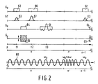
- spin echo cycles are shown for producing resonance signals, the phase of a reference signal 60 obtained by the oscillator 11 being modified between a sequence n and a sequence n + 1 in the time interval n′.
- the frequency of the reference signal 60 is not drawn to scale with respect to the sequences n and n + 1 and to the time interval n′ for the sake of clarity.
- the spin echo sequence n shown for producing a resonance signal 61 will be described, after which there is indicated how a phase variation between the sequences n and n + 1 is obtained.
- a method of determining a nuclear magnetization from magnetic resonance signals 61 produced in sequences in a body 21 is carried out with an NMR arrangement described with reference to Fig. 1.
- the method comprises the repetition of a spin echo sequence (or any other pulse gradient sequence), the sequence being repeated so frequently that a sufficient quantity of information is collected by means of resonance signals 61 about, for example, (a part of) the body 21 so that, for example, a spin nuclei density distribution may be reconstructed therefrom by the programmed computer means 30 in the processing device 15 .
- a number of spin nuclei are resonantly selectively excited in the body 21 in a number of cycles by exciting in the presence of a magnetic field gradient 62 in the z direction G z produced from the central unit 16 driven by the programmed computer means 30, the spin nuclei by means of a high-frequency electromagnetic pulse 63 (having a given band width around the frequency ⁇ O of the oscillator 11) produced by the transmitter device at the instant t1 and also from the control unit 16 driven by the programmed computer means, which pulse is, for example, a so-called 90° pulse, that is to say a pulse which rotates through 90° a magnetization vector M (not shown) in a plane at right angles to the z axis.
- a high-frequency electromagnetic pulse 63 having a given band width around the frequency ⁇ O of the oscillator 11
- the spin nuclei rotated (selectively) at right angles to the z axis will perform a precessional movement around the magnetic field B O , but will be shifted in phase (lose their coherence) between the instants t1 and t2.
- the magnetic field gradients G x and G y , 64, 65 are activated for encoding the resonance signal 62.
- G x is then fixed and G y , the so-called preparation gradient, assumes a different value for each sequence.
- G z is activated again (66) and the body 21 is (selectively) excited with a 180° pulse (67).
- the resonance signal 61 will occur (echo) around the instant t3, which resonance signal 61 is sampled after demodulation by the quadrature phase-sensitive detector 23 by the analog-to-digital converters 28, 29, which are driven via the programmed computer means 30.
- the frequency of the oscillator 11 is varied in the period n′ by the control unit 16, which is driven from the programmed computer means 30, as a result of which a phase shift is obtained in the resonance signal produced by the oscillator 11.
- the duration of the period n′ or the frequency sweep ⁇ is varied from the programmed computer means 30, the extent of the phase shift can be controlled.
- the programmed computer means 30 reconstruct from sampled values (not shown) obtained by a large number of resonance signals 61 the spin nuclei density distribution with, for example, a bidimensional discrete Fourier transformation (in the embodiment shown, two dimensions are obtained: by variation of the preparation gradient and by sampling); this is a generally known method of reconstructing images from sampled values, in NMR. (FFT Fast Fourier Transform is a known algorithm in this context).
- the value of the phase of the reference signal 60 is varied randomly, as a result of which coherent interference effects, which become manifest, for example, as interference lines in an image without the use of the method, are smeared out as noise in the image with the use of the method.
- the class of interference effects reduced by the method according to the invention comprises NMR signals, which "leak through" from one sequence to a next sequence, for example from the sequence n to the sequence n+1.
- interference effects occur, which become manifest in the reconstructed image as conspicuous dots.
- the method according to the invention smears these conspicuous dots out into a line having a considerably lower intensity. Furthermore, there is a reduction in the coherent interference effects which is caused, for example, by hum from the feeding STET device 8 for the gradient coils 4, 5, 6, and also in the coherent interference effects caused by mechanical oscillations in the NMR arrangement (for example typically having a frequency of 8 Hz; for example vibrations in the floor or vibrations in the patient table 22).
- the last-mentioned interference effects cause phantom images in the absence of the method according to the invention herein described.
Landscapes
- Physics & Mathematics (AREA)
- Health & Medical Sciences (AREA)
- General Health & Medical Sciences (AREA)
- Nuclear Medicine, Radiotherapy & Molecular Imaging (AREA)
- Radiology & Medical Imaging (AREA)
- Engineering & Computer Science (AREA)
- Signal Processing (AREA)
- High Energy & Nuclear Physics (AREA)
- Condensed Matter Physics & Semiconductors (AREA)
- General Physics & Mathematics (AREA)
- Magnetic Resonance Imaging Apparatus (AREA)
Claims (5)
Applications Claiming Priority (2)
| Application Number | Priority Date | Filing Date | Title |
|---|---|---|---|
| NL8700266A NL8700266A (nl) | 1987-02-04 | 1987-02-04 | Werkwijze en inrichting voor het onderdrukken van coherente storingen bij magnetische resonantiesignalen. |
| NL8700266 | 1987-02-04 |
Publications (2)
| Publication Number | Publication Date |
|---|---|
| EP0283058A1 EP0283058A1 (de) | 1988-09-21 |
| EP0283058B1 true EP0283058B1 (de) | 1991-06-05 |
Family
ID=19849517
Family Applications (1)
| Application Number | Title | Priority Date | Filing Date |
|---|---|---|---|
| EP88200145A Expired EP0283058B1 (de) | 1987-02-04 | 1988-01-28 | Verfahren und Vorrichtung zur Unterdrückung der kohärenten Interferenzeffekte von kernmagnetischen Resonanzsignalen |
Country Status (7)
| Country | Link |
|---|---|
| US (1) | US4873487A (de) |
| EP (1) | EP0283058B1 (de) |
| JP (1) | JP2661935B2 (de) |
| CA (1) | CA1256166A (de) |
| DE (1) | DE3863098D1 (de) |
| IL (1) | IL85278A0 (de) |
| NL (1) | NL8700266A (de) |
Families Citing this family (2)
| Publication number | Priority date | Publication date | Assignee | Title |
|---|---|---|---|---|
| JP3183915B2 (ja) * | 1991-09-03 | 2001-07-09 | 株式会社東芝 | 磁気共鳴イメージング装置 |
| DE69211806T2 (de) * | 1991-10-25 | 1996-10-31 | Univ Queensland | Korrektur von Signalverzerrungen in einem magnetischen Kernresonanzapparat |
Family Cites Families (8)
| Publication number | Priority date | Publication date | Assignee | Title |
|---|---|---|---|---|
| US3968424A (en) * | 1974-08-01 | 1976-07-06 | Varian Associates | Fourier transform NMR spectroscopy employing a phase modulated rf carrier |
| CA1052861A (en) * | 1975-03-18 | 1979-04-17 | Varian Associates | Gyromagnetic resonance fourier transform zeugmatography |
| US4191919A (en) * | 1978-05-22 | 1980-03-04 | Varian Associates, Inc. | Fast NMR acquisition processor |
| US4318043A (en) * | 1978-07-20 | 1982-03-02 | The Regents Of The University Of California | Method and apparatus for rapid NMR imaging of nuclear densities within an object |
| JPS59166846A (ja) * | 1983-03-11 | 1984-09-20 | Toshiba Corp | 磁気共鳴イメージング装置 |
| JPS61745A (ja) * | 1984-06-13 | 1986-01-06 | Toshiba Corp | 核磁気共鳴装置 |
| US4695800A (en) * | 1985-06-06 | 1987-09-22 | Technicare Corporation | Non harmonic NMR spin echo imaging |
| US4673880A (en) * | 1985-08-16 | 1987-06-16 | Technicare Corporation | Phase sensitive detection in multislice magnetic resonance imaging systems |
-
1987
- 1987-02-04 NL NL8700266A patent/NL8700266A/nl unknown
- 1987-05-27 US US07/054,476 patent/US4873487A/en not_active Expired - Lifetime
-
1988
- 1988-01-28 DE DE8888200145T patent/DE3863098D1/de not_active Expired - Lifetime
- 1988-01-28 EP EP88200145A patent/EP0283058B1/de not_active Expired
- 1988-02-01 CA CA000557864A patent/CA1256166A/en not_active Expired
- 1988-02-01 IL IL85278A patent/IL85278A0/xx unknown
- 1988-02-03 JP JP63022141A patent/JP2661935B2/ja not_active Expired - Lifetime
Also Published As
| Publication number | Publication date |
|---|---|
| JP2661935B2 (ja) | 1997-10-08 |
| IL85278A0 (en) | 1988-07-31 |
| DE3863098D1 (de) | 1991-07-11 |
| EP0283058A1 (de) | 1988-09-21 |
| NL8700266A (nl) | 1988-09-01 |
| US4873487A (en) | 1989-10-10 |
| CA1256166A (en) | 1989-06-20 |
| JPS63200746A (ja) | 1988-08-19 |
Similar Documents
| Publication | Publication Date | Title |
|---|---|---|
| US4318043A (en) | Method and apparatus for rapid NMR imaging of nuclear densities within an object | |
| US5168226A (en) | Acquisition of multiple images in fast spin echo nmr scans | |
| US5285158A (en) | NMR angiography using fast pulse sequences with preparatory pulses | |
| EP0086972B2 (de) | NMR-Abbildungsverfahren zur Überwindung der T2*-Effekte in einem inhomogenen statischen magnetischen Feld | |
| US4952877A (en) | RF synthesizer or an NMR instrument | |
| US6078176A (en) | Fast spin echo pulse sequence for diffusion weighted imaging | |
| US4665365A (en) | Method for reversing residual transverse magnetization due to phase-encoding magnetic field gradients | |
| US4536712A (en) | Method and apparatus for examination by nuclear magnetic resonance | |
| US5212448A (en) | Nmr pulse sequence with burst rf excitation pulses having separately controlled phase | |
| US6265873B1 (en) | Non-CPMG fast spin echo MRI method | |
| GB2026172A (en) | Method and apparatus for determining the relative densities of nuclei within an object using nuclear magnetic resonance | |
| EP0322968B1 (de) | Verfahren und Anordnung zum Erzeugen verschachtelter Mehrscheiben-Mehrecho-Impulsfolgen für Bilderzeugung mittels magnetischer Resonanz | |
| US4587489A (en) | Method for rapid acquisition of NMR data | |
| US4528509A (en) | Spatially selective NMR | |
| US5281916A (en) | NMR angiography using fast spin echo pulse sequences | |
| US4845430A (en) | Magnetic resonance imaging system | |
| JPH05329127A (ja) | 磁気共鳴イメージング装置 | |
| US4777439A (en) | Spatially localized spectroscopy | |
| EP0359298A1 (de) | Verfahren zur heteronuklearen Entkopplung in Kernspinresonanz-Spektroskopie und Anordnung zum Bestimmen eines Spektrums | |
| US5233302A (en) | Masking motion ghost artifacts in NMR images | |
| US4873487A (en) | Method and arrangement for suppressing coherent interferences in magnetic resonance signals | |
| GB2105853A (en) | Spatially selective NMR | |
| US4825160A (en) | Method and device for MR tomography | |
| USRE33279E (en) | Method for rapid acquisition of NMR data | |
| JPS6218863B2 (de) |
Legal Events
| Date | Code | Title | Description |
|---|---|---|---|
| PUAI | Public reference made under article 153(3) epc to a published international application that has entered the european phase |
Free format text: ORIGINAL CODE: 0009012 |
|
| AK | Designated contracting states |
Kind code of ref document: A1 Designated state(s): DE FR GB NL SE |
|
| 17P | Request for examination filed |
Effective date: 19890316 |
|
| 17Q | First examination report despatched |
Effective date: 19900615 |
|
| GRAA | (expected) grant |
Free format text: ORIGINAL CODE: 0009210 |
|
| AK | Designated contracting states |
Kind code of ref document: B1 Designated state(s): DE FR GB NL SE |
|
| PG25 | Lapsed in a contracting state [announced via postgrant information from national office to epo] |
Ref country code: NL Effective date: 19910605 Ref country code: SE Effective date: 19910605 |
|
| REF | Corresponds to: |
Ref document number: 3863098 Country of ref document: DE Date of ref document: 19910711 |
|
| ET | Fr: translation filed | ||
| NLV1 | Nl: lapsed or annulled due to failure to fulfill the requirements of art. 29p and 29m of the patents act | ||
| PLBE | No opposition filed within time limit |
Free format text: ORIGINAL CODE: 0009261 |
|
| STAA | Information on the status of an ep patent application or granted ep patent |
Free format text: STATUS: NO OPPOSITION FILED WITHIN TIME LIMIT |
|
| 26N | No opposition filed | ||
| REG | Reference to a national code |
Ref country code: FR Ref legal event code: CD |
|
| REG | Reference to a national code |
Ref country code: FR Ref legal event code: CD |
|
| REG | Reference to a national code |
Ref country code: GB Ref legal event code: IF02 |
|
| REG | Reference to a national code |
Ref country code: GB Ref legal event code: 746 Effective date: 20020923 |
|
| REG | Reference to a national code |
Ref country code: FR Ref legal event code: D6 |
|
| PGFP | Annual fee paid to national office [announced via postgrant information from national office to epo] |
Ref country code: GB Payment date: 20070129 Year of fee payment: 20 |
|
| PGFP | Annual fee paid to national office [announced via postgrant information from national office to epo] |
Ref country code: DE Payment date: 20070312 Year of fee payment: 20 |
|
| REG | Reference to a national code |
Ref country code: GB Ref legal event code: PE20 |
|
| PGFP | Annual fee paid to national office [announced via postgrant information from national office to epo] |
Ref country code: FR Payment date: 20070129 Year of fee payment: 20 |
|
| PG25 | Lapsed in a contracting state [announced via postgrant information from national office to epo] |
Ref country code: GB Free format text: LAPSE BECAUSE OF EXPIRATION OF PROTECTION Effective date: 20080127 |