EP0283102A2 - Appareil de traitement d'ébauches d'emballages sous forme de sac - Google Patents
Appareil de traitement d'ébauches d'emballages sous forme de sac Download PDFInfo
- Publication number
- EP0283102A2 EP0283102A2 EP88200509A EP88200509A EP0283102A2 EP 0283102 A2 EP0283102 A2 EP 0283102A2 EP 88200509 A EP88200509 A EP 88200509A EP 88200509 A EP88200509 A EP 88200509A EP 0283102 A2 EP0283102 A2 EP 0283102A2
- Authority
- EP
- European Patent Office
- Prior art keywords
- pair
- forming plates
- press
- movable
- support member
- Prior art date
- Legal status (The legal status is an assumption and is not a legal conclusion. Google has not performed a legal analysis and makes no representation as to the accuracy of the status listed.)
- Granted
Links
Images



Classifications
-
- B—PERFORMING OPERATIONS; TRANSPORTING
- B65—CONVEYING; PACKING; STORING; HANDLING THIN OR FILAMENTARY MATERIAL
- B65B—MACHINES, APPARATUS OR DEVICES FOR, OR METHODS OF, PACKAGING ARTICLES OR MATERIALS; UNPACKING
- B65B43/00—Forming, feeding, opening or setting-up containers or receptacles in association with packaging
- B65B43/08—Forming three-dimensional [3D] containers from sheet material
-
- B—PERFORMING OPERATIONS; TRANSPORTING
- B31—MAKING ARTICLES OF PAPER, CARDBOARD OR MATERIAL WORKED IN A MANNER ANALOGOUS TO PAPER; WORKING PAPER, CARDBOARD OR MATERIAL WORKED IN A MANNER ANALOGOUS TO PAPER
- B31B—MAKING CONTAINERS OF PAPER, CARDBOARD OR MATERIAL WORKED IN A MANNER ANALOGOUS TO PAPER
- B31B2150/00—Flexible containers made from sheets or blanks, e.g. from flattened tubes
-
- B—PERFORMING OPERATIONS; TRANSPORTING
- B31—MAKING ARTICLES OF PAPER, CARDBOARD OR MATERIAL WORKED IN A MANNER ANALOGOUS TO PAPER; WORKING PAPER, CARDBOARD OR MATERIAL WORKED IN A MANNER ANALOGOUS TO PAPER
- B31B—MAKING CONTAINERS OF PAPER, CARDBOARD OR MATERIAL WORKED IN A MANNER ANALOGOUS TO PAPER
- B31B2150/00—Flexible containers made from sheets or blanks, e.g. from flattened tubes
- B31B2150/001—Flexible containers made from sheets or blanks, e.g. from flattened tubes with square or cross bottom
- B31B2150/0016—Flexible containers made from sheets or blanks, e.g. from flattened tubes with square or cross bottom made from already formed bags
-
- B—PERFORMING OPERATIONS; TRANSPORTING
- B31—MAKING ARTICLES OF PAPER, CARDBOARD OR MATERIAL WORKED IN A MANNER ANALOGOUS TO PAPER; WORKING PAPER, CARDBOARD OR MATERIAL WORKED IN A MANNER ANALOGOUS TO PAPER
- B31B—MAKING CONTAINERS OF PAPER, CARDBOARD OR MATERIAL WORKED IN A MANNER ANALOGOUS TO PAPER
- B31B2160/00—Shape of flexible containers
- B31B2160/20—Shape of flexible containers with structural provision for thickness of contents
Definitions
- the present invention relates to an apparatus for processing baglike container blanks for use in a packaging machine for producing rectangular parallelepipedal containers filled with milk or like contents.
- Apparatus of this type heretofore known include one which is adapted to process baglike container blanks each having a thermoplastic synthetic resin layer on each of its opposite surfaces by folding a pair of triangular ears flat while projecting the ears sidewise from the portion of each blank to be made into the bottom of a finished rectangular parallelepipedal container, and press-bonding the projected triangular ears to outer surface portions of the trunk wall of the container at the lateral sides thereof after folding the ears over the lateral side portions.
- each triangular ear E is press-bonded to the lateral side portion by fitting the container blank B around a pair of forming plates 11, 12 arranged at a distance from each other in parallel, and then pressing a press bonding member 13 against the ear E.
- the lateral side portion over which the ear E is folded is therefore subjected to the pressure and becomes damaged.
- this portion has a sealed seam S produced when the blank B is formed, the base portion of the seam S indicated by an arrow is liable to damage locally, with the resulting likelihood that a polyethylene layer forming the blank B will break to develop a pinhole at the base portion.
- the main object of the present invention is to provide an apparatus for processing baglike container blanks free of the above problem.
- the present invention provides an apparatus for processing baglike container blanks each having a thermoplastic synthetic resin layer on each of its opposite surfaces by folding a pair of triangular ears flat while projecting the ears sidewise from the portion of each blank to be made into the bottom of a finished rectangular parallelepipidal container, and press-bonding the projected triangular ears to outer surface portions of the trunk wall of the container at the lateral sides thereof after folding the ears over the outer surface portions.
- the apparatus comprises an apparatus frame having a plurality of stations arranged along a circumference at equal spacings, one of the stations being a press bonding station; a horizontal rotary drum intermittently drivingly movable and having stationary forming plates and movable forming plates, the stationary forming plates being arranged at equal spacings and identical in number to the number of the stations, the movable forming plates being opposed to the respective stationary forming plates in pairs each stoppable at each of the stations while traveling from station to station, the stationary and movable forming plates having a width equal to the spacing between the inner surfaces of lateral sides of the container trunk wall, each of the movable forming plates being pivotally movable to a position where the opposed plates in each pair are closed to a wedgelike form with their forward ends in contact with each other or to a position where the opposed forming plates are open and parallel to each other with their outer surfaces spaced apart by a distance equal to the spacing between the inner surfaces of the front and rear sides of the container trunk wall; and a press bonding
- each of the press members is pressed against the support member with the triangular ear and the lateral side trunk wall portion of the blank interposed therebetween for the support member to withstand the pressure of the press member. Unlike the conventional apparatus, this obviates the likelihood that the pressure will cause damage to the lateral side portion over which the ear is folded.
- the container blank B to be processed thereby will be described.
- the blank B is prepared from a paper-base sheet having a polyethylene layer on each surface thereof, by folding the sheet in two to form three lapped side edge portions and forming a sealed seam S at each of the two parallel lapped edge portions to obtain a bag.
- the bottom portion of the blank B is so bent that a pair of triangular ears E are folded flat while causing the ears to project sidewise from the portion of the blank to be made into the bottom of a finished container, and the projected triangular ears E are folded over and bonded to the trunk wall of the container.
- the processing apparatus comprises an apparatus frame disposed above the starting end of a path of transport by a container conveyor C and having six stations, i.e., feeding, folding, heating, press bonding, transfer and idling stations I to VI which are arranged along a circumference at equal spacings.
- the apparatus further comprises a horizontal rotary drum 53 intermittently drivingly movable and having six radial stationary forming plates 51 and six radial movable forming plates 52 opposed to the respective plates 51 in pairs. Each pair of forming plates 51 and 52 stops at each of the six processing stations I to VI while traveling from station to station.
- each of the movable forming plates 52 is pivotally movable by unillustrated means to a position where the opposed forming plates 51, 52 in each pair are closed to a wedgelike form with their forward ends in contact with each other, while at the other stations II to VI, each movable forming plate 52 is similarly movable to a position where the opposed forming plates 51, 52 are open and parallel to each other.
- the feeding station I is provided with a feeder 54 by which the blank B folded flat has its open end opened and fitted around the forming plates 51, 52 at rest at the station I.
- the folding station II is provided with a folding unit 55 for folding the bottom portion of the blank B fitted around the pair of forming plates 51, 52 while causing a pair of triangular ears E to project from the portion to be made into the bottom of a finished container.
- the heating station III is provided with a heater 56 for heating the projected ears E from the rear. Extending from the heating station III to the press bonding station IV is a bending guide 15 for bending the pair of heated triangular ears E over outer surface portions of the trunk wall of the container at the lateral sides thereof.
- the press bonding station IV is provided with a press bonding device 57 for press bonding the bent ears E to the lateral side portions of the trunk wall.
- a transfer unit 58 is disposed by which the processed blank B is removed from the pair of forming plates and transferred onto the conveyor C so as to be sent to the subsequent process.
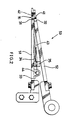
- Fig. 1 shows the ear press bonding device 57 and the pair of stationary and movable forming plates 51, 52 at rest at the press bonding station IV.
- a support member 16 is disposed between the forming plates 51, 52.
- the ear press bonding device 57 comprises a pair of press members 21 of elastic material opposed to each other and arranged at opposite sides of the path of travel of the opposed forming plates 51, 52. Each of the press members 21 is attached to the piston rod 23 of a hydraulic cylinder 22.
- the hydraulic cylinder 22 is horizontally disposed at the other side of the press member 21 opposite to the side thereof facing the path of travel and is attached to the apparatus frame 24.
- the ear bending guide 15 extends to a position close to the press bonding device 57 and is in the form of a round bar over its entire width.
- the guide 15 is provided at its terminal end with a pair of rectangular flat guide plates 25, with the press member 21 inserted in a hole 26 formed in each plate 25.
- the stationary and movable forming plates 51, 52 are generally identical with each other in configuration and rectangular, and have a width equal to the spacing between the inner surfaces of lateral sides of the container trunk wall as finished. When the plates 51, 52 are opened, their outer surfaces are spaced apart by a distance equal to the spacing between the inner surfaces of the front and rear sides of the container trunk wall.
- the forming plates 51, 52 are supported at their base ends on the rotary drum 53 by suitable means, while the movable forming plate 52 is movable by known means, such as a cam mechanism.
- the forming plates 51, 52 have cutouts 31, 32, respectively, formed in their opposite side edges and positioned close to their forward ends.
- the stationary forming plate 52 is formed on its inner surface with a pair of projections 33 opposed to each other and positioned close to its base end.
- the plate 52 has a plate spring 34 screwed to the inner surface and positioned closer to its forward end than the projections 33, and a gatelike stopper 35 provided over the spring 34 and bolted to the inner surface at opposite sides of the spring.
- the support member 16 comprises a pair of trapezoidal support pieces 41 and a connecting piece 42 in the form of a rectangular flat plate and interconnectign the support pieces 41.
- a pivotal arm 43 is joined at its forward end to the connecting piece 42 at the midportion of its length.
- the pivotal arm 43 has at its base end a support rod 45 which is rotatably supported by bolts 44 each extending through the projection 33 into the rod.
- the arm 43 is held at a position close to its base end between the free end of the plate spring 34 and the stopper 35.
- the arm 43 With the forming plates 51, 52 in the open state, the arm 43 is held in contact with the stopper 35 by the action of the plate spring 34, holding the two support pieces 41 opposed to the respective press members 21.
- the movable forming member 52 when moved from this state toward the stationary plate 51, causes its forward end to push the connecting piece 42 of the support member 16, thereby moving the support member 16 toward the stationary forming plate 51 against the action of the plate spring 34.
- the two support pieces 41 are accommodated in the cutouts 31, 32 of the two forming plates 51, 52 as seen in Fig. 2.
- the two forming plates 51, 52 are held open with the two support pieces 41 opposed to the respective press members 21.
- the press members 21 are brought toward each other by the operation of the hydraulic cylinders 22, the lateral side trunk wall portion and each triangular ear E folded thereover are pressed against the support piece 41 of the support member 16 by each of the press members 21.
Landscapes
- Engineering & Computer Science (AREA)
- Mechanical Engineering (AREA)
- Making Paper Articles (AREA)
- Supplying Of Containers To The Packaging Station (AREA)
Applications Claiming Priority (2)
| Application Number | Priority Date | Filing Date | Title |
|---|---|---|---|
| JP67581/87 | 1987-03-20 | ||
| JP62067581A JP2552477B2 (ja) | 1987-03-20 | 1987-03-20 | 袋状容器素材の成形装置 |
Publications (3)
| Publication Number | Publication Date |
|---|---|
| EP0283102A2 true EP0283102A2 (fr) | 1988-09-21 |
| EP0283102A3 EP0283102A3 (en) | 1989-05-03 |
| EP0283102B1 EP0283102B1 (fr) | 1992-07-29 |
Family
ID=13349034
Family Applications (1)
| Application Number | Title | Priority Date | Filing Date |
|---|---|---|---|
| EP88200509A Expired - Lifetime EP0283102B1 (fr) | 1987-03-20 | 1988-03-18 | Appareil de traitement d'ébauches d'emballages sous forme de sac |
Country Status (4)
| Country | Link |
|---|---|
| US (1) | US4804356A (fr) |
| EP (1) | EP0283102B1 (fr) |
| JP (1) | JP2552477B2 (fr) |
| DE (1) | DE3873125T2 (fr) |
Cited By (3)
| Publication number | Priority date | Publication date | Assignee | Title |
|---|---|---|---|---|
| DE19504802A1 (de) * | 1995-02-14 | 1996-08-22 | Rovema Gmbh | Vorrichtung und Verfahren zur Aufnahme und zum Weitertransport offener Beutel |
| EP0819602A3 (fr) * | 1996-07-15 | 1998-05-27 | Shikoku Kakoki Co., Ltd. | Dispositif pour coller des volets rabattables dans une machine d'emballage |
| FR2854834A1 (fr) * | 2003-05-16 | 2004-11-19 | Keepcool Internat General Part | Machine plieuse pour la production de sacs a fond plat plies a partir de sacs a fond droit, utilisation de ladite machine et procede utilisant ladite machine |
Families Citing this family (5)
| Publication number | Priority date | Publication date | Assignee | Title |
|---|---|---|---|---|
| WO1996003272A1 (fr) * | 1994-07-25 | 1996-02-08 | Lin Pac, Inc. | Procede et appareil de fabrication de sacs en plastique se maintenant debout |
| US5694746A (en) * | 1994-12-20 | 1997-12-09 | Chung; Yun H. | Paperboard package and method for forming same |
| SE510055C2 (sv) * | 1997-08-14 | 1999-04-12 | Tetra Laval Holdings & Finance | Sätt vid formning av förpackningsbehållare |
| JP7119306B2 (ja) * | 2017-07-25 | 2022-08-17 | 凸版印刷株式会社 | 包装容器への内容物の充填方法 |
| WO2021193759A1 (fr) * | 2020-03-26 | 2021-09-30 | 株式会社細川洋行 | Procédé de fabrication de sac d'emballage à fond rectangulaire, dispositif de fabrication de sac d'emballage à fond rectangulaire, procédé de fabrication de corps d'emballage, et dispositif de fabrication de corps d'emballage |
Family Cites Families (6)
| Publication number | Priority date | Publication date | Assignee | Title |
|---|---|---|---|---|
| US2245675A (en) * | 1936-11-17 | 1941-06-17 | Pneumatic Scale Corp | Method of making paper bags |
| US2307990A (en) * | 1939-04-08 | 1943-01-12 | Cons Packaging Machinery Corp | Bag opening, shaping, and filling device |
| US2381850A (en) * | 1943-06-07 | 1945-08-07 | Bemis Bro Bag Co | Method of making bag bodies |
| DE1043057B (de) * | 1956-01-25 | 1958-11-06 | Habra Werk Ott Kg | Vorrichtung zum Herstellen von Klotzboden-Beuteln oder -Saecken |
| CH390666A (de) * | 1961-03-07 | 1965-04-15 | Hesser Ag Maschf | Verfahren und Vorrichtung zum maschinellen Herstellen von Bodenbeuteln |
| FR1426341A (fr) * | 1964-12-17 | 1966-01-28 | Rochette Cenpa | Gabarit pour mise en forme des outres d'emballages et autres objets analogues |
-
1987
- 1987-03-20 JP JP62067581A patent/JP2552477B2/ja not_active Expired - Lifetime
-
1988
- 1988-03-18 US US07/170,199 patent/US4804356A/en not_active Expired - Lifetime
- 1988-03-18 DE DE8888200509T patent/DE3873125T2/de not_active Expired - Lifetime
- 1988-03-18 EP EP88200509A patent/EP0283102B1/fr not_active Expired - Lifetime
Cited By (5)
| Publication number | Priority date | Publication date | Assignee | Title |
|---|---|---|---|---|
| DE19504802A1 (de) * | 1995-02-14 | 1996-08-22 | Rovema Gmbh | Vorrichtung und Verfahren zur Aufnahme und zum Weitertransport offener Beutel |
| EP0819602A3 (fr) * | 1996-07-15 | 1998-05-27 | Shikoku Kakoki Co., Ltd. | Dispositif pour coller des volets rabattables dans une machine d'emballage |
| US5836139A (en) * | 1996-07-15 | 1998-11-17 | Shikoku Kakoki Co., Ltd. | Ear bonding device for use in packaging machines |
| FR2854834A1 (fr) * | 2003-05-16 | 2004-11-19 | Keepcool Internat General Part | Machine plieuse pour la production de sacs a fond plat plies a partir de sacs a fond droit, utilisation de ladite machine et procede utilisant ladite machine |
| WO2004101264A1 (fr) * | 2003-05-16 | 2004-11-25 | Keepcool International General Partnership | Procede et dispositif permettant de fabriquer un sac a fond plat replie a partir dun sac plat |
Also Published As
| Publication number | Publication date |
|---|---|
| EP0283102B1 (fr) | 1992-07-29 |
| JP2552477B2 (ja) | 1996-11-13 |
| DE3873125D1 (de) | 1992-09-03 |
| EP0283102A3 (en) | 1989-05-03 |
| US4804356A (en) | 1989-02-14 |
| DE3873125T2 (de) | 1992-12-03 |
| JPS63248620A (ja) | 1988-10-14 |
Similar Documents
| Publication | Publication Date | Title |
|---|---|---|
| US5120292A (en) | Apparatus for forming containers | |
| US5267934A (en) | Carton pour spout fitment applicator | |
| EP0528272B1 (fr) | Dispositif et procédé pour la fabrication d'un récipient de fluide | |
| US4044528A (en) | Method and apparatus for forming sealed packages | |
| US4804356A (en) | Apparatus for processing baglike container blanks | |
| US5752907A (en) | Cup making machine | |
| EP0999135B1 (fr) | Machine d'emballage | |
| US4528803A (en) | Machine for the fabrication, filling, and sealing of packages | |
| US5150562A (en) | Method and apparatus for packaging resiliently deformable articles | |
| EP0117537B1 (fr) | Dispositif pour relever les flancs des boîtes d'emballage tubulaires et aplatis | |
| WO1996009959A1 (fr) | Appareil et procede de transport d'un carton d'emballage | |
| EP0466271B1 (fr) | Appareil pour coller les parties supérieures de récipients | |
| US2466341A (en) | Container forming machine | |
| US4280865A (en) | Synchronized drive for heat sealing roller anvils | |
| JP4146019B2 (ja) | 包装装置の成形型 | |
| JPH0333575B2 (fr) | ||
| JPH07195587A (ja) | 筒状体成形装置 | |
| EP0904193B1 (fr) | Machine pour produire des boites a partir d'ebauches en resine synthetique | |
| JP2865317B2 (ja) | 紙容器底部組立装置 | |
| JP4156046B2 (ja) | 内容物充填方法およびその装置 | |
| WO2025100144A1 (fr) | Dispositif de moulage d'élément cylindrique | |
| GB709454A (en) | Improvements in or relating to a method of closing and a machine for forming a carton | |
| US4104849A (en) | Container sealing apparatus | |
| JPH0624329Y2 (ja) | 容器脱気シール装置 | |
| JPH0544252Y2 (fr) |
Legal Events
| Date | Code | Title | Description |
|---|---|---|---|
| PUAI | Public reference made under article 153(3) epc to a published international application that has entered the european phase |
Free format text: ORIGINAL CODE: 0009012 |
|
| AK | Designated contracting states |
Kind code of ref document: A2 Designated state(s): CH DE FR GB LI NL SE |
|
| PUAL | Search report despatched |
Free format text: ORIGINAL CODE: 0009013 |
|
| AK | Designated contracting states |
Kind code of ref document: A3 Designated state(s): CH DE FR GB LI NL SE |
|
| 17P | Request for examination filed |
Effective date: 19891102 |
|
| 17Q | First examination report despatched |
Effective date: 19910531 |
|
| GRAA | (expected) grant |
Free format text: ORIGINAL CODE: 0009210 |
|
| AK | Designated contracting states |
Kind code of ref document: B1 Designated state(s): CH DE FR GB LI NL SE |
|
| REF | Corresponds to: |
Ref document number: 3873125 Country of ref document: DE Date of ref document: 19920903 |
|
| ET | Fr: translation filed | ||
| PLBE | No opposition filed within time limit |
Free format text: ORIGINAL CODE: 0009261 |
|
| STAA | Information on the status of an ep patent application or granted ep patent |
Free format text: STATUS: NO OPPOSITION FILED WITHIN TIME LIMIT |
|
| 26N | No opposition filed | ||
| EAL | Se: european patent in force in sweden |
Ref document number: 88200509.3 |
|
| REG | Reference to a national code |
Ref country code: GB Ref legal event code: IF02 |
|
| PGFP | Annual fee paid to national office [announced via postgrant information from national office to epo] |
Ref country code: DE Payment date: 20020214 Year of fee payment: 15 |
|
| PGFP | Annual fee paid to national office [announced via postgrant information from national office to epo] |
Ref country code: GB Payment date: 20020307 Year of fee payment: 15 |
|
| PGFP | Annual fee paid to national office [announced via postgrant information from national office to epo] |
Ref country code: SE Payment date: 20020318 Year of fee payment: 15 |
|
| PGFP | Annual fee paid to national office [announced via postgrant information from national office to epo] |
Ref country code: FR Payment date: 20020325 Year of fee payment: 15 |
|
| PGFP | Annual fee paid to national office [announced via postgrant information from national office to epo] |
Ref country code: CH Payment date: 20020326 Year of fee payment: 15 |
|
| PGFP | Annual fee paid to national office [announced via postgrant information from national office to epo] |
Ref country code: NL Payment date: 20020328 Year of fee payment: 15 |
|
| PG25 | Lapsed in a contracting state [announced via postgrant information from national office to epo] |
Ref country code: GB Free format text: LAPSE BECAUSE OF NON-PAYMENT OF DUE FEES Effective date: 20030318 |
|
| PG25 | Lapsed in a contracting state [announced via postgrant information from national office to epo] |
Ref country code: SE Free format text: LAPSE BECAUSE OF NON-PAYMENT OF DUE FEES Effective date: 20030319 |
|
| PG25 | Lapsed in a contracting state [announced via postgrant information from national office to epo] |
Ref country code: LI Free format text: LAPSE BECAUSE OF NON-PAYMENT OF DUE FEES Effective date: 20030331 Ref country code: CH Free format text: LAPSE BECAUSE OF NON-PAYMENT OF DUE FEES Effective date: 20030331 |
|
| PG25 | Lapsed in a contracting state [announced via postgrant information from national office to epo] |
Ref country code: NL Free format text: LAPSE BECAUSE OF NON-PAYMENT OF DUE FEES Effective date: 20031001 Ref country code: DE Free format text: LAPSE BECAUSE OF NON-PAYMENT OF DUE FEES Effective date: 20031001 |
|
| EUG | Se: european patent has lapsed | ||
| GBPC | Gb: european patent ceased through non-payment of renewal fee |
Effective date: 20030318 |
|
| REG | Reference to a national code |
Ref country code: CH Ref legal event code: PL |
|
| PG25 | Lapsed in a contracting state [announced via postgrant information from national office to epo] |
Ref country code: FR Free format text: LAPSE BECAUSE OF NON-PAYMENT OF DUE FEES Effective date: 20031127 |
|
| NLV4 | Nl: lapsed or anulled due to non-payment of the annual fee |
Effective date: 20031001 |
|
| REG | Reference to a national code |
Ref country code: FR Ref legal event code: ST |