EP0283111A2 - Absorbeur d'ondulations pour appareil à dessiner - Google Patents
Absorbeur d'ondulations pour appareil à dessiner Download PDFInfo
- Publication number
- EP0283111A2 EP0283111A2 EP88300395A EP88300395A EP0283111A2 EP 0283111 A2 EP0283111 A2 EP 0283111A2 EP 88300395 A EP88300395 A EP 88300395A EP 88300395 A EP88300395 A EP 88300395A EP 0283111 A2 EP0283111 A2 EP 0283111A2
- Authority
- EP
- European Patent Office
- Prior art keywords
- medium
- isolator
- wave isolator
- wave
- platen
- Prior art date
- Legal status (The legal status is an assumption and is not a legal conclusion. Google has not performed a legal analysis and makes no representation as to the accuracy of the status listed.)
- Granted
Links
Images


Classifications
-
- G—PHYSICS
- G01—MEASURING; TESTING
- G01D—MEASURING NOT SPECIALLY ADAPTED FOR A SPECIFIC VARIABLE; ARRANGEMENTS FOR MEASURING TWO OR MORE VARIABLES NOT COVERED IN A SINGLE OTHER SUBCLASS; TARIFF METERING APPARATUS; MEASURING OR TESTING NOT OTHERWISE PROVIDED FOR
- G01D15/00—Component parts of recorders for measuring arrangements not specially adapted for a specific variable
- G01D15/28—Holding means for recording surfaces; Guiding means for recording surfaces; Exchanging means for recording surfaces
Definitions
- the present application relates to large format drafting plotters, and, more particularly, to isolating dynamic media waves on the plotting medium that interfere with the pen.
- the first problem is the formation of waves in the medium, which travel up the platen and interfere with the pen. These waves are large enough to lift the pen from the medium or even strike the pen while it is in the pen-up position. These phenomona are known, respectively, as the skip and the drag.
- the second problem is the scalloping of lines drawn on an angle (angled vectors) during high acceleration. Since the medium is being driven only by its edges parallel to the direction of motion, the center of the medium tends to lag until constant velocity is reached. Although this is only slightly noticeable on vectors longer than 15 mm, it is glaringly obvious on shorter vectors, especially those used to generate characters.
- One solution used in response to the medium wave problem is a firmware filter.
- This filter looks at incoming vectors, and based on an algorithm which is a function of velocity, acceleration, move length, and move direction, slows the plotter down to twice the acceleration of gravity (2g) from a maximum of 4g.
- This solution increases plot time by an average of 10% for typical demonstration plots. This average, however, does not indicate an even distribution. Rather, some plots are clustered around 5% and others around 20%. In the worst case, plot time may be increased by 40%. High throughput in both sheet and roll mode is seriously compromised if much of the plot time is spent at 2g.
- the scalloping problem has also received a firmware fix.
- the solution consists of pulsing the acceleration on angled vectors so that the pen is actually ahead of its intended position. Consequently, the pen does not compensate enough in the middle of the sheet and over-compensates near the edges under the pinch rollers. This transforms line quality from poor in the center and perfect at the edges to consistently poor everywhere, but marginally passable.
- a moving node wave isolator for preventing waves, generated in the medium during plotting, from travelling up the platen and interfering with the pen.
- the wave isolator comprises a thin flexible cantilevered beam having a length substantially the same as that of the plotter chassis and a mass negligible in comparison with that of the medium.
- the cantilevered beam is leafed preferably obtained by layering three strips of flexible film, attached along the length of the chassis.
- the first and major advantage of the invention is that the moving node wave isolator allows for high speed, high acceleration on both sheet and roll media without the aid of firmware "fixes".
- the device of the invention has been tested up to 6g acceleration, where it achieved a 97% reduction in the number of drags for roll media and an 88% reduction in the number of drags for sheet media, compared to presently available commercial plotters.
- the drafting plotter includes the usual elements of a carriage for supporting a pen, a motor for driving the carriage bidirectionally and orthogonal to the direction of the plotting medium, a carosel or turret for storing a quantity of pens for plotting, means for rotating the turret to select a particular pen, and a microprocessor for controlling these elements.
- Such elements are commonly known for such plotters and are not shown herein.
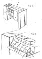
- Additional elements of such plotters germane to the following discussion include a chassis 12 and platen 14 for supporting a medium 16 upon which a plot is made.
- an isolator 18 keeps waves from reaching the pen 20. As mentioned earlier, such waves are generated in the medium 16 during the plotting operation, and travel up the chassis, where they adversely affect the plotting operation. By preventing the waves from traveling up the chassis 12, the isolator 18 acts as a mechanical wave absorber.
- the isolator 18 of the invention comprises a beveled or leafed cantilever, which is preferably approximated by use of three layers, or strips, 22a, 22b and 22c.
- the layers comprise thin strips of flexible thermoplastic material.
- An example of a preferred material is a polyimide film, such as that available from E. I. duPont de Nemours, Inc. (Wilmington, DE) under the tradename "Kapton".
- the strips 22a, 22b, 22c are of three different widths, arranged so that the widest is on top and the narrowest in on the bottom.
- the strips adhere to one another only along the edge which is attached to the plotter (FIG. 4). This allows the strips to slip relative to one another during bending, supporting no shear load between layers, making the composite plate more compliant than a single strip of similar geometry.
- bonding the three layers together at the common edge which attaches to the plotter provides a thicker base to withstand the effects of bending loads over time, known as creep.
- the three layers are all of substantially the same length, running the length of the chassis 12.
- the top layer 22a is about 1018 mm long, while the other two layers 22b, 22c are each about 1005 mm long.
- the top layer is formed to the same length as the chassis 12, while the other layers are somewhat shorter to allow for assembly tolerances.
- the composite approximates a tapered plate, but will be less stiff due to no shear stress between layers.
- the relationship of the widths w preferably ranges from about 3w:2w:w to 4w:2w:w. If all layers were the same width, the bottom layers would curl away from the top layer, providing no support, and posing a risk of the operator being cut by the edge of the film.
- the top layer 22a is 4 mils thick and about 3-1/16 inches wide, with a hem 24 formed by folding the free edge over a length of double sided foam tape 26, 1/4 inch wide and 1/8 inch thick.
- the hem 24 prevents the operator from cuts on the thin film, provides stability of the top layer 22a by making the edge rigid, and adds a finished cosmetic appearance to the isolator 18.
- the other two layers 22b, 22c are 3 mils thick and are 2 inches and 1 inch, respectively, in width.
- Layer 22a most preferably comprises Kapton 400H or 400HN, coated with a thin (about 0.2 mils) film of a thermoset acrylic resin with additives, including conductive carbon black and polyethylene.
- the coating provides wear resistance, a low coefficient of friction, and bleeds off static charge caused by the movement of the medium 16.
- the coating is readily applied in the liquid form to the top layer 22a, such as by dipping, spraying or coating with a slot head coater in which the coating is "extruded" onto the thin film.
- Layers 22b and 22c most preferably comprise Kapton 300HN, and are not coated. These layers are not visible, but act as stiffening members to approximate a beveled cantilever beam, as mentioned above.
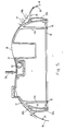
- the wave isolator 18 is mounted on both the front and rear of chassis 12 by an isolator clamp and cap assembly 28, comprising an isolator clamp 28a and a cap 28b.
- the isolator clamp 28a is retained on chassis strut 12a by a bottom plate 30 which is attached to the chassis strut by a nut and stud assembly 13.
- the clamp 28a positions the isolator 18 vertically a distance from the bottom of the chassis 12. For the chassis of the particular plotter depicted herein, the optimal distance is about 70 mm.
- the cap 28b provides a transition for the edge of the medium 16, as it moves back and forth over the intersection of the isolator 18 and the chassis 12.
- the cap 28b also provides a cosmetic cover for this intersection and prevents the isolator 18 from being easily stripped away from the clamp 28a.
- the first principle of operation is that a moving node, provided by the wave isolator 18 of the invention, at the edge of the plotter 10 will reflect dynamic waves in the medium 16 and not allow them to travel up the platen 14.
- This essentially acts as a mechanical filter, which allows only high frequency, small amplitude waves to pass. The waves that do pass are small enough to be eliminated by the vacuum force holding the medium 16 to the platen surface.
- the wave isolator 18 holds the medium 16 away from the chassis 12, forming a volume of air between the medium and the platen. This air gap acts as a damper, pumping air in and out as the wave isolator 18 of the invention reacts to the moving medium 16.
- the second principle of operation of the invention relies on the fact that the medium 16 is supported by the isolator 18, which allows for movement of the medium 16 normal to the plane of the medium. This is important, since it reduces the inertial load of the free-hanging medium on that portion which is under the pen 20 (as shown in FIG. 6). This inertial load is manifested as bowing of angled lines, and is particularly noticeable when these lines are drawn at the top center or bottom center of the medium 16. This effect is pronounced in the rendering of alpha-numeric characters where curved portions will appear scalloped.
- FIG. 6 depicts the plotter chassis 12 with medium 16 held in place by pinch wheels 32 bearing down on a grit covered shaft 34.
- the platen 14, clamp 28a and cap 28b are not shown for simplicity.
- the carriage which holds the pen 20 and the brackets which supply force on the pinch wheels 32 are also not shown.
- the medium 16 is driven by the grit shaft 34; however, the medium is pinched onto the grit shaft only at its edges, that is, directly beneath the pinch wheels 32.
- the fact that the rest of the medium moves at all is due to the stiffness of the medium itself. It may be appreciated that if the medium 16 were a very compliant material, for example, a wet beach towel, the center of the medium 16 in the vicinity of the pen 20 would lag behind the two edges directly beneath the pinch wheels 32.
- the function of the isolator 18 of the invention is to isolate the free-hanging mass of the medium 16 (that is, that portion of the medium which hangs below the isolator) from that which lies between the front and rear isolators.
- the wave isolator effect may be created one of two ways: active or passive.
- the active approach requires an electronically controlled motor which would drive a rigid isolator in the direction of medium motion during acceleration of the medium and then return to a neutral position during constant velocity motion of the medium. This would require an additional motor, controlling firmware, and several moving parts to be effective. Cost constraints thus rule out the active approach.
- the passive approach has two options.
- the wave isolator 18 may be externally sprung, or it may rely on its own internal spring rate to supply the needed frequency response.
- the internal spring rate isolator (the device of choice) is shown in FIGS. 2-4. What makes the internal spring rate approach so attractive is that is has a variable frequency response and practically no mass. Because the flexible strip 22a itself has very little mass, the frequency response is largely determined by the mass of the medium 16 draped over it. This allows the wave isolator 18 to respond to any frequency capable of being generated in the medium 14.
- FIG. 2 depicts a cross-section of a drafting plotter chassis with wave isolators 18 along its front and rear edges.
- the wave isolators 18 extend the entire length of the chassis.
- the wave isolator 18 When medium 16 is mounted in the plotter 10, the wave isolator 18 will deflect as shown in FIG. 5. When the medium 16 is accelerated, several things happen. First, the wave isolator 18 which sees the medium accelerating upward (left side of FIG. 5) will deflect under the increased inertial load. At the same time, air trapped between the medium 16 and the chassis 12 exits at the sides of the medium, dissipating some of the energy of the medium. Meanwhile, at the front of the plotter 10 where the medium 16 is accelerating downward, the wave isolator 18 sees a negative change in load and responds by flexing upward. This tends to increase the volume of air between the medium 16 and the chassis 12, creating a low pressure area which sucks air in at the sides, again dissipating the medium's energy.
- the amount of deflection changes.
- the wave isolator 18 As the mass of the medium 16 hanging off the edge of the wave isolator 18 changes (due to pen position on the medium), the amount of deflection changes.
- the wave isolator 18 When less medium 16 is supported by the wave isolator 18, it will have a higher natural frequency. Since the medium mass is smaller, the input wave frequency of the free medium matches the resonant frequency of the isolator 18. Conversely, when medium mass is greater, the system will have a lower natural frequency.
- the flexible strip 22a since the same mass which produced the lower natural frequency governs the input frequency to the wave isolator 18, the flexible strip 22a will again respond to the input caused by medium acceleration. Indeed, because the flexible strip 22a is nearly massless, the wave isolator 18 as a system has nearly zero lag. Thus, it will always be able to respond to any frequency caused by a combination of acceleration, velocity, and move length. This forms a moving node which tracks the medium 16 and reflects dynamic
- the moving node wave isolator 18 is expected to find use in large format drafting plotters 10. Further, the configuration of the wave isolater permits retrofit of existing plotters, thereby permitting its use in existing plotters as well as prospective plotters in preventing wave motion of the medium from adversely affecting the pen and its operation.
Landscapes
- Physics & Mathematics (AREA)
- General Physics & Mathematics (AREA)
- Recording Measured Values (AREA)
- Handling Of Cut Paper (AREA)
Applications Claiming Priority (2)
| Application Number | Priority Date | Filing Date | Title |
|---|---|---|---|
| US07/019,409 US4734987A (en) | 1987-02-26 | 1987-02-26 | Moving node wave isolator for drafting plotters |
| US19409 | 1987-02-26 |
Publications (3)
| Publication Number | Publication Date |
|---|---|
| EP0283111A2 true EP0283111A2 (fr) | 1988-09-21 |
| EP0283111A3 EP0283111A3 (en) | 1989-10-04 |
| EP0283111B1 EP0283111B1 (fr) | 1993-03-03 |
Family
ID=21793053
Family Applications (1)
| Application Number | Title | Priority Date | Filing Date |
|---|---|---|---|
| EP88300395A Expired - Lifetime EP0283111B1 (fr) | 1987-02-26 | 1988-01-19 | Absorbeur d'ondulations pour appareil à dessiner |
Country Status (5)
| Country | Link |
|---|---|
| US (1) | US4734987A (fr) |
| EP (1) | EP0283111B1 (fr) |
| JP (1) | JP2662535B2 (fr) |
| CA (1) | CA1285540C (fr) |
| DE (1) | DE3878707T2 (fr) |
Families Citing this family (11)
| Publication number | Priority date | Publication date | Assignee | Title |
|---|---|---|---|---|
| FR2623902B1 (fr) * | 1987-11-26 | 1990-05-04 | Schlumberger Ind Sa | Traceur ayant un plateau de support de feuille a profil angulaire |
| FR2677784B1 (fr) * | 1991-06-17 | 1993-10-15 | Oce Graphics France Sa | Procede de suppression de vibrations indesirables du support d'impression dans un traceur de type vectoriel, et traceur mettant en óoeuvre ce procede. |
| WO1994023274A1 (fr) * | 1993-03-31 | 1994-10-13 | Summagraphics Corporation | Jupe adaptable pour un traceur a dessin |
| JPH1035186A (ja) * | 1996-07-19 | 1998-02-10 | Mutoh Ind Ltd | 自動製図機 |
| US6786664B2 (en) * | 2001-10-26 | 2004-09-07 | Hewlett-Packard Development Company, L.P. | Active vacuum roller and method for advancing media |
| JP4742155B2 (ja) * | 2009-03-18 | 2011-08-10 | キヤノン株式会社 | シート供給装置、及び該シート供給装置を備えたプリンタ |
| JP6186703B2 (ja) * | 2012-11-12 | 2017-08-30 | セイコーエプソン株式会社 | 搬送装置及び記録装置 |
| JP6365815B2 (ja) * | 2014-01-20 | 2018-08-01 | セイコーエプソン株式会社 | 記録装置 |
| US10900748B2 (en) * | 2014-03-04 | 2021-01-26 | Sheltered Wings, Inc. | System and method for producing a DOPE chart |
| US10987953B2 (en) * | 2014-09-25 | 2021-04-27 | Hewlett-Packard Development Company, L.P. | Re-feed prevention |
| JP6846143B2 (ja) * | 2016-09-06 | 2021-03-24 | 東芝テック株式会社 | プリントユニット、及びプリンタ |
Family Cites Families (9)
| Publication number | Priority date | Publication date | Assignee | Title |
|---|---|---|---|---|
| US3908810A (en) * | 1974-06-19 | 1975-09-30 | Teletype Corp | Printer paper roll holder with spring-controlled line feed tensioner |
| US4234886A (en) * | 1979-01-22 | 1980-11-18 | Alden Research Foundation | Electric graphic recorder |
| US4467525A (en) * | 1982-07-26 | 1984-08-28 | Gerber Scientific Products, Inc. | Automated sign generator |
| JPS5983591U (ja) * | 1982-11-29 | 1984-06-06 | 日立精工株式会社 | 自動製図機の用紙ガイド |
| US4665619A (en) * | 1983-01-24 | 1987-05-19 | Gerber Garment Technology, Inc. | Method and apparatus for working on sheet material |
| US4512079A (en) * | 1983-07-21 | 1985-04-23 | Gerber Garment Technology, Inc. | Method and apparatus for indexing sheet material |
| US4547968A (en) * | 1984-05-03 | 1985-10-22 | Bausch & Lomb Incorporated | Desktop plotter instrument |
| US4654675A (en) * | 1984-06-27 | 1987-03-31 | Mutoh Industry Ltd. | Paper feeding device for automatic drafting machine |
| JPS61175521A (ja) * | 1985-01-30 | 1986-08-07 | Graphtec Corp | ロ−ラ記録装置 |
-
1987
- 1987-02-26 US US07/019,409 patent/US4734987A/en not_active Expired - Lifetime
-
1988
- 1988-01-19 DE DE8888300395T patent/DE3878707T2/de not_active Expired - Fee Related
- 1988-01-19 EP EP88300395A patent/EP0283111B1/fr not_active Expired - Lifetime
- 1988-02-04 CA CA000558152A patent/CA1285540C/fr not_active Expired - Lifetime
- 1988-02-26 JP JP63045678A patent/JP2662535B2/ja not_active Expired - Fee Related
Also Published As
| Publication number | Publication date |
|---|---|
| DE3878707T2 (de) | 1993-09-16 |
| DE3878707D1 (de) | 1993-04-08 |
| EP0283111A3 (en) | 1989-10-04 |
| US4734987A (en) | 1988-04-05 |
| JPS63231999A (ja) | 1988-09-28 |
| EP0283111B1 (fr) | 1993-03-03 |
| CA1285540C (fr) | 1991-07-02 |
| JP2662535B2 (ja) | 1997-10-15 |
Similar Documents
| Publication | Publication Date | Title |
|---|---|---|
| US4734987A (en) | Moving node wave isolator for drafting plotters | |
| US5812684A (en) | Passenger compartment noise attenuation apparatus for use in a motor vehicle | |
| US20020122561A1 (en) | Elastomeric dielectric polymer film sonic actuator | |
| EP0063600B1 (fr) | Traceur possedant un rouleau porte-papier concave | |
| US4477822A (en) | Graphic recorder | |
| JPH028097A (ja) | 角度の付いた形状の支持プラテンを持ったプロッタ | |
| JP2668712B2 (ja) | トランスデューサ支持装置および回転円板型記録装置 | |
| JPS60135322A (ja) | 自動車のルーフ装置 | |
| US20190047640A1 (en) | Viscous drag reduction apparatus for vehicles | |
| US4301205A (en) | Device for fastening objects on a flat support member | |
| WO1994023274A1 (fr) | Jupe adaptable pour un traceur a dessin | |
| JPH09118270A (ja) | 車両の空気抵抗低減装置 | |
| JP2002211771A (ja) | プリンタ媒体つまみ取り装置 | |
| US6299161B1 (en) | Apparatus for guiding a paper in a printer | |
| EP1523005A2 (fr) | Tourne-disque | |
| US5945771A (en) | Vibration wave driven motor and a printing apparatus | |
| CA1106822A (fr) | Ruban bobine | |
| US3966108A (en) | Inertia isolator | |
| US6161973A (en) | Ink-jet image forming device | |
| EP0213875B1 (fr) | Tête d'enregistrement et bras de support pour milieu d'enregistrement à surface tendue | |
| JP2739597B2 (ja) | ウエブの無接触搬送装置 | |
| EP0674301A1 (fr) | Cadre pour affiches avec film extensible en plastique | |
| JPS63149889A (ja) | 浮動ヘツドスライダ支持機構 | |
| JPH0461674A (ja) | 磁気ヘッドスライダの加圧支持装置 | |
| JPH07284710A (ja) | 塗布装置 |
Legal Events
| Date | Code | Title | Description |
|---|---|---|---|
| PUAI | Public reference made under article 153(3) epc to a published international application that has entered the european phase |
Free format text: ORIGINAL CODE: 0009012 |
|
| AK | Designated contracting states |
Kind code of ref document: A2 Designated state(s): DE FR GB IT |
|
| PUAL | Search report despatched |
Free format text: ORIGINAL CODE: 0009013 |
|
| AK | Designated contracting states |
Kind code of ref document: A3 Designated state(s): DE FR GB IT |
|
| 17P | Request for examination filed |
Effective date: 19900313 |
|
| 17Q | First examination report despatched |
Effective date: 19910402 |
|
| ITF | It: translation for a ep patent filed | ||
| GRAA | (expected) grant |
Free format text: ORIGINAL CODE: 0009210 |
|
| AK | Designated contracting states |
Kind code of ref document: B1 Designated state(s): DE FR GB IT |
|
| REF | Corresponds to: |
Ref document number: 3878707 Country of ref document: DE Date of ref document: 19930408 |
|
| ET | Fr: translation filed | ||
| PLBE | No opposition filed within time limit |
Free format text: ORIGINAL CODE: 0009261 |
|
| STAA | Information on the status of an ep patent application or granted ep patent |
Free format text: STATUS: NO OPPOSITION FILED WITHIN TIME LIMIT |
|
| 26N | No opposition filed | ||
| PGFP | Annual fee paid to national office [announced via postgrant information from national office to epo] |
Ref country code: FR Payment date: 19951213 Year of fee payment: 9 |
|
| PGFP | Annual fee paid to national office [announced via postgrant information from national office to epo] |
Ref country code: GB Payment date: 19951228 Year of fee payment: 9 Ref country code: DE Payment date: 19951228 Year of fee payment: 9 |
|
| PG25 | Lapsed in a contracting state [announced via postgrant information from national office to epo] |
Ref country code: GB Effective date: 19970119 |
|
| GBPC | Gb: european patent ceased through non-payment of renewal fee |
Effective date: 19970119 |
|
| PG25 | Lapsed in a contracting state [announced via postgrant information from national office to epo] |
Ref country code: FR Effective date: 19970930 |
|
| PG25 | Lapsed in a contracting state [announced via postgrant information from national office to epo] |
Ref country code: DE Effective date: 19971001 |
|
| REG | Reference to a national code |
Ref country code: FR Ref legal event code: ST |
|
| PG25 | Lapsed in a contracting state [announced via postgrant information from national office to epo] |
Ref country code: IT Free format text: LAPSE BECAUSE OF NON-PAYMENT OF DUE FEES;WARNING: LAPSES OF ITALIAN PATENTS WITH EFFECTIVE DATE BEFORE 2007 MAY HAVE OCCURRED AT ANY TIME BEFORE 2007. THE CORRECT EFFECTIVE DATE MAY BE DIFFERENT FROM THE ONE RECORDED. Effective date: 20050119 |