EP0283236A2 - Duschentür - Google Patents
Duschentür Download PDFInfo
- Publication number
- EP0283236A2 EP0283236A2 EP88302229A EP88302229A EP0283236A2 EP 0283236 A2 EP0283236 A2 EP 0283236A2 EP 88302229 A EP88302229 A EP 88302229A EP 88302229 A EP88302229 A EP 88302229A EP 0283236 A2 EP0283236 A2 EP 0283236A2
- Authority
- EP
- European Patent Office
- Prior art keywords
- door
- hinge
- panel
- tongue
- panels
- Prior art date
- Legal status (The legal status is an assumption and is not a legal conclusion. Google has not performed a legal analysis and makes no representation as to the accuracy of the status listed.)
- Withdrawn
Links
Images


Classifications
-
- A—HUMAN NECESSITIES
- A47—FURNITURE; DOMESTIC ARTICLES OR APPLIANCES; COFFEE MILLS; SPICE MILLS; SUCTION CLEANERS IN GENERAL
- A47K—SANITARY EQUIPMENT; ACCESSORIES THEREFOR, e.g. TOILET ACCESSORIES
- A47K3/00—Baths; Showers; Appurtenances therefor
- A47K3/28—Showers or bathing douches
- A47K3/30—Screens or collapsible cabinets for showers or baths
- A47K3/36—Articulated screens
-
- A—HUMAN NECESSITIES
- A47—FURNITURE; DOMESTIC ARTICLES OR APPLIANCES; COFFEE MILLS; SPICE MILLS; SUCTION CLEANERS IN GENERAL
- A47K—SANITARY EQUIPMENT; ACCESSORIES THEREFOR, e.g. TOILET ACCESSORIES
- A47K3/00—Baths; Showers; Appurtenances therefor
- A47K3/28—Showers or bathing douches
- A47K3/30—Screens or collapsible cabinets for showers or baths
- A47K3/302—Screens or collapsible cabinets for showers or baths splash guards
Definitions
- This invention relates to doors. It particularly relates to doors for showers or the like, although it is not limited thereto.
- the doors are normally supported by a frame.
- the frame has several functions in terms of clearly defining the plane of shut of the doors, and in the case of suspension doors, in terms of transferring the weight of the doors, generally onto the edge of a bath or shower stall.
- the width of the frame is readily adjusted to accommodate bath enclosures of different widths; it is not required to adjust the width of the doors as such, as they are intended to overlap, and the degree of overlap is not of concern.
- a door comprises a vertically elongated panel having obverse and reverse faces.
- a pair of vertically spaced apart tubular rails open at the laterally opposed ends thereof are disposed on the obverse face of the panel.
- a cap having a tongue is telescopically received within the tubular rail to close each end thereof;
- a plurality of caps at one lateral side of the panel include a hinge element portion which may for example combine with an identical hinge element portion of an adjacent panel and a hinge-pin to form a hinge for rotatably securing the adjacent panels together.
- the caps are secured by fastening means insertible into the tongue from the reverse face to retain the tongue in its telescoped position while simultaneously securing the rail to the panels.
- the panels are each provided with an upper and a lower pair of relatively large openings therethrough
- the fastening means includes a diametrically enlarged body portion closely surrounded by a panel openings, and a stalk of reduced diameter in comparison to the body projecting therefrom at one axial end thereof in axial alignment therewith.
- the stalk has an enlarged end adapted to snap fit behind an opening in the tongue to thereby retain the tongue in the telescoped position.
- the door includes at least one rail including a cap therefor horizontally disposed on the reverse face of a panel in opposition to a rail disposed on the obverse face thereof, and the fastening means, where used for securing the opposed rails, includes a second stalk of reduced diameter projecting from the other axial end of the body in axial opposition to the first stalk, the second stalk also having an enlarged end adapted to snap fit behind an opening in the tongue of the cap of the opposing rail.
- a folding door comprises a support column having a plurality of support elements of adjustable length extending generally horizontally therefrom.
- a hinge means is provided for rotatably supporting the door from each support element, such hinge means including indexing means defining the plane of shut of the door.
- the hinge means includes means for adjusting the indexing means relative to the support elements.
- the means for adjusting the indexing means includes a sleeve mounted in fixed relation to each support element, a bushing mounted in the sleeve in interfering fit therewith, and means for rotating the bushing relative to the sleeve.
- a frameless shower door comprises a pair of hingedly interconnected panels, each panel comprising a pair of parallel, transversely spaced apart axially elongated sheets interconnected by a plurality of axially extending spacer walls to form a hollow structure, and a resilient gasket extending about the periphery of each panel to provide a seal therearound.
- the gasket has in transverse cross-section a U shape in which the bight portion of the U shape is hollow, to thereby provide a readily compressible sealing surface between adjacent panels.
- the panels are hingedly interconnected by demountable hinges, and the hinges are secured to the panels by means which delocalizes the stress forces over a relatively wide area of said panel.
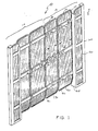
- Door 10 comprises a right hand section 12 and an left hand section 14. These sections 12,14 are mirror images; most of the components of which the sections are comprised are symmetric, and are used on both the left hand and right hand sections, hence door 10 will be described with reference to only one section. Those components that are asymetric will be defined.
- Section 12 comprises a pair of panels 16,18, with panel 16 locating nearest to a support for the section.
- the major surface of panels 16 and 18 is identified as the obverse face 20, and the opposed major surface as reverse face 22.
- the obverse face is considered in this embodiment to be outward facing, which is to say outwardly of a bath or shower to be enclosed by door 10.
- this arrangement is somewhat arbitrary, and the reverse face could equally be outwardly facing.
- Panels 16,18 have longitudinal edges 24,26 28,30, and are interconnected and supported by hinge means 31 as will be further described in greater detail.
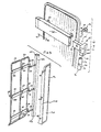
- Rails 32 and 34 are each closed at the end thereof adjacent panel edge 30 by an end cap 38, and rail 36 by an interlock cap 40.
- Rails 32, 34, 36 are closed at the ends thereof adjacent the other longitudinal panel edges by hinge caps 42.
- Caps 38, 40, 42 each include a rail closure portion 44 at one end thereof and a tongue 46 projecting therefrom having a recessed opening 48 therethrough.
- Tongues 46 are snugly receiveable in the respective ends of the rails 32, 34, 36 each have blind openings 50 on the face thereof contacting obverse face 20 of panels 16,18, in register with tongue openings 48.
- Panels 16,18 are provided with a plurality of openings 52 therein, in register with openings 48 and 50.
- Rails 32 and 34 are fastened to panels 16,18 by the use of single ended connectors 54.
- Connectors 54 comprise a relatively large head 56, a body 58 which is snug fit in a panel opening 52, and a stalk 60 which is of reduced diametric dimension in comparison with body 58, and which is coaxial therewith.
- Stalk 60 terminates with a tip 62 having a diametric dimension intermediate that of body 58 and stalk 60.
- An axially aligned slot 63 is provided in tip 62 and stalk 60.
- Rail blind openings 50 are dimensioned to permit the free passage of tip 62, while recessed tongue openings 48 are adapted to capture the tip upon it being forced therethrough under pressure.
- hinge caps 42 are secured to panels 16,18 so as to delocalize the forces transmitted to the panels over a relatively wide area, and thereby reduce the incidence of stress cracking of the panels, which may thus be relatively light structured.
- Mid-rails 36 serve an additional purpose as handles for door 10, and for this purpose a similar mid-rail 36 ⁇ is fastened to the reverse face 22 of panels 16,18 in opposition to rail 36.
- Double ended connectors 64 are provided for this purpose; such connectors comprise a body 58 ⁇ from which there projects coaxially at each side thereof a stalk 60 ⁇ having a tipped end 62 ⁇ , which are slotted at 63 ⁇ in an analagous arrangement to single ended connector 54.
- Rail 36 ⁇ is closed with end caps 38 at the ends thereof adjacent the hinged panel edges 24,26,28 and by an interlocking cap 40 at the end thereof adjacent the non-hinged panel edge 30.
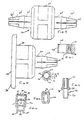
- Hinge cap 42 includes a cup 66 having a vertical axis which is forwardly offset from the plane of tongue 46, so as to locate the hinge axis in a plane more remote from both the obverse face 20 and the reverse face 22 of panel 16. It will be appreciated that hinge caps 42 have an asymmetry, and that the corresponding hinge caps used in the left hand section 14 will be a mirror image of those used in the right hand section. Cup 66 has a rim 68 which locates in the medial axial horizontal plane of a rail into which a hinge cap 42 is secured, whereby the hinge caps locating at adjacent panel edges 26,28 will have their rims 68 in abutment and the rails in horizontal alignment.
- Adjacent hinge caps are mated by a hinge-pin 70 having an upper end 72 which is an interference fit in upper cup 66, and a lower end 74 which is freely rotatable in a lower cup 66, so as to hingedly interconnected panels 16,18 in a demountable manner.
- Hinge-pins 70 could equally be reversed, which is to say the interfering end 72 thereof could be located in a lower cup 66, and the freely rotatable end 74 in an upper cup.
- Rim 68 is provided with a pair of opposed V notches 77 therein located on a diameter of cup 66 such that the notches of mating cups are coincident when panels 16,18 are in their shut coplanar position.
- Hinge-pin 70 is provided with a pair of diametrically opposed projections 78 having a square on-edge cross section; the interfering end 72 of hinge-pin 70 is located in a cup 66 with projections 78 seated in notches 76, so as to be in register therewith, the notches of the opposed cup then providing a seating for projections 78 when the panels are in the shut position, to thereby provide an index for the door.
- Panels 16,18 suitably comprise a hollow construction formed by spaced apart major surfaces presenting themselves as obverse and reverse faces 20,22 interconnected by spacer strips 80, conveniently molded as a unitary sheet extrusion. Panels 16,18 are planar in the upper portions thereof, but it will be remarked that the lower portion is rearwardly downwardly inclined at 90 to direct water flowing down the reverse face 22 of door 10 inwardly into a bath or shower pan. Panels 16,18 are sealed about their periphery with a resilient gasket 92 which has a U shaped cross-section.
- the bight portion 94 of the gasket is hollow at 96, thereby permitting the abutting faces of the gasket between adjacent panels 16,18, and also between adjacent sections 12,14, to be easily compressed and sealed together when door 10 is shut, so as to restrict the passage of water between the panels. Such compression is facilitated by locally reducing the wall thickness of gasket 96 in the bight portion 94 and adjacent thereto, as at 98.
- a breathing channel 100 is formed in the inner wall of gasket 92 defining bight portion 94.
- Door 10 further comprises a support column 100 which presents a relatively large surface area for the convenient securement of the column to a hollow support wall, using standard fixing techniques.
- the lower end of support column 100 will normally abut the edge of a bath or a shower pan, thereby receiving much of the load formed by the weight of the door carried by the support column.
- Door support rods 102 are provided which screwingly correct to support column 100, whereby the effective length of the support rods may be easily varied.
- a hinge element 104 comprising a saddle 106 and a sleeve 108 having a vertical axis offset from the plane containing the support rod in a direction opposed to the offset of cups 66, which is to say in a direction towards obverse face 20.
- Sleeve 108 has a somewhat larger axial opening therein than cup 66, and accommodates a bushing 110 in interfering fit therewith.
- Bushing 110 has the same internal diameter as cup 66, and a rim 112 which mounts an opposed rim 68 of a cup.
- Rim 112 has a first pair of diametrically opposed V notches 114 therein, and a second pair of V notches 116 in a diameter orthogonal to that on which the first pair reside.
- a hinge-pin 70 interconnects sleeve 108 and its mating cup 66, with the projections 78 seated in notches 114.
- Sleeve 108 has a pair of flats 118 on the external wall thereof adjacent rim 112, to permit the sleeve to be rotated about its axis by a wrench. Accordingly, the plane of shut of door 10 can be easily adjusted relative to the horizontal angle of support column 100 and any enclosure wall to which it is secured.
- Door 10 further includes a side panel 120, one longitudinal edge of which is floating and is recessed in a continuous slot 122 provided in support column 100.
- the opposed longitudinal edge of side panel 120 is supported from the distal ends of support rods 102 by a baffle 124 which connects to the support rods by machine screws 126, screwed axial bores being provided in the support rods for this purpose.
- the floating arrangement thus permits the adjustment in length of support rods 102 to be automatically accommodated.
- the overall width of door 10 may be regulated to provide for differently sized wall enclosures to which the doors are to be fitted, and also to accommodate variations in the verticality of the walls and support columns 100 secured thereto.
- Interlock caps 40 are formed with a claw 130 extending therefrom in a direction opposed to tongue 46 on one lateral side of the cap, so as to overlap an adjacent panel when door 10 is closed.
- Each pair of panels 12,14 along the longitudinal edge 30,30L thereof remote from a support column is provided with a similar pair of claws 130 which together retain the door 10 in a closed position.
- the width of panel 18 is made somewhat less than that of panel 16.
- the offset of panels 16,18 from support rods 102 permits panels 16,18 when in their folded position, to rotate inwardly, in which position they would project over a bath or shower pan, or outwardly, in which position they would project outwardly from the bath or shower pan, in 180° opposition to their inwardly rotated position.
- door 10 When in either the inwardly or outwardly rotated position door 10 will be retained in position by the indexing means provided by V notches 116 formed on bushing 110.
Landscapes
- Health & Medical Sciences (AREA)
- Public Health (AREA)
- Epidemiology (AREA)
- General Health & Medical Sciences (AREA)
- Residential Or Office Buildings (AREA)
Applications Claiming Priority (2)
| Application Number | Priority Date | Filing Date | Title |
|---|---|---|---|
| US2790387A | 1987-03-19 | 1987-03-19 | |
| US27903 | 1987-03-19 |
Publications (2)
| Publication Number | Publication Date |
|---|---|
| EP0283236A2 true EP0283236A2 (de) | 1988-09-21 |
| EP0283236A3 EP0283236A3 (de) | 1989-03-08 |
Family
ID=21840431
Family Applications (1)
| Application Number | Title | Priority Date | Filing Date |
|---|---|---|---|
| EP88302229A Withdrawn EP0283236A3 (de) | 1987-03-19 | 1988-03-15 | Duschentür |
Country Status (1)
| Country | Link |
|---|---|
| EP (1) | EP0283236A3 (de) |
Cited By (2)
| Publication number | Priority date | Publication date | Assignee | Title |
|---|---|---|---|---|
| US5123129A (en) * | 1988-08-10 | 1992-06-23 | Lyons Donald D | Waterproof hinged panel assembly |
| GB2410766A (en) * | 2004-02-06 | 2005-08-10 | Bsh Bosch Siemens Hausgeraete | Hinge mounting unit for door |
Family Cites Families (3)
| Publication number | Priority date | Publication date | Assignee | Title |
|---|---|---|---|---|
| DE2952574C2 (de) * | 1979-12-28 | 1982-12-09 | ACO Gießerei und Kunststoffverarbeitung GmbH & Co, 5470 Andernach | Duschabtrennung für Bade- oder Duschwannen |
| FR2483506B1 (fr) * | 1980-05-28 | 1985-08-09 | Milleret Joanny | Portail a plusieurs vantaux rabattables |
| DE3310139A1 (de) * | 1983-03-21 | 1984-09-27 | Joachim 2400 Lübeck Groth | Duschabtrennung |
-
1988
- 1988-03-15 EP EP88302229A patent/EP0283236A3/de not_active Withdrawn
Cited By (3)
| Publication number | Priority date | Publication date | Assignee | Title |
|---|---|---|---|---|
| US5123129A (en) * | 1988-08-10 | 1992-06-23 | Lyons Donald D | Waterproof hinged panel assembly |
| GB2410766A (en) * | 2004-02-06 | 2005-08-10 | Bsh Bosch Siemens Hausgeraete | Hinge mounting unit for door |
| GB2410766B (en) * | 2004-02-06 | 2006-05-17 | Bsh Bosch Siemens Hausgeraete | Hinge assembly in a cooking appliance door |
Also Published As
| Publication number | Publication date |
|---|---|
| EP0283236A3 (de) | 1989-03-08 |
Similar Documents
| Publication | Publication Date | Title |
|---|---|---|
| US5806946A (en) | Switchgear cabinet with frame | |
| EP0740519B1 (de) | Verstellbare zarge | |
| IE813095L (en) | Adjustable door jamb assembly | |
| US6283565B1 (en) | Adjustable hinge for a switch cupboard | |
| EP0283236A2 (de) | Duschentür | |
| US5772296A (en) | Switchgear cabinet | |
| CA1288681C (en) | Shower door | |
| AU575523B2 (en) | Shower partition | |
| US7178198B2 (en) | Mounting arrangement for glass doors | |
| US5921050A (en) | Device for fitting a front frame to a housing | |
| EP1061223B1 (de) | Scharnierbeschlag für Rahmen von Türen, Fenstern oder Ähnlichem | |
| KR200497550Y1 (ko) | 시공편의성이 향상되고 도어 위치조절기능을 갖는 샤워부스용 창호 시스템 | |
| AU597209B2 (en) | Shower partition | |
| JPH0425465Y2 (de) | ||
| CH628949A5 (en) | Refrigerator with a hinge for a refrigerator door | |
| JPS6212073Y2 (de) | ||
| GB2276199A (en) | Adjustable hinge assembly | |
| JPH0826720B2 (ja) | 蝶 番 | |
| KR200233669Y1 (ko) | 문짝설치용 경첩 | |
| JP2991711B1 (ja) | コンクリ―ト躯体直付け用のヒンジ金物 | |
| JPH0239039Y2 (de) | ||
| CN86101175A (zh) | 淋浴隔板墙 | |
| JPH0223747Y2 (de) | ||
| JPH0328145Y2 (de) | ||
| JPS606529Y2 (ja) | ガラス扉の取付装置 |
Legal Events
| Date | Code | Title | Description |
|---|---|---|---|
| PUAI | Public reference made under article 153(3) epc to a published international application that has entered the european phase |
Free format text: ORIGINAL CODE: 0009012 |
|
| AK | Designated contracting states |
Kind code of ref document: A2 Designated state(s): AT BE CH DE ES FR GB IT LI NL SE |
|
| PUAL | Search report despatched |
Free format text: ORIGINAL CODE: 0009013 |
|
| AK | Designated contracting states |
Kind code of ref document: A3 Designated state(s): AT BE CH DE ES FR GB IT LI NL SE |
|
| STAA | Information on the status of an ep patent application or granted ep patent |
Free format text: STATUS: THE APPLICATION IS DEEMED TO BE WITHDRAWN |
|
| 18D | Application deemed to be withdrawn |
Effective date: 19890909 |