EP0283328B1 - Correcteur de freinage asservi à la charge d'un véhicule - Google Patents
Correcteur de freinage asservi à la charge d'un véhicule Download PDFInfo
- Publication number
- EP0283328B1 EP0283328B1 EP88400172A EP88400172A EP0283328B1 EP 0283328 B1 EP0283328 B1 EP 0283328B1 EP 88400172 A EP88400172 A EP 88400172A EP 88400172 A EP88400172 A EP 88400172A EP 0283328 B1 EP0283328 B1 EP 0283328B1
- Authority
- EP
- European Patent Office
- Prior art keywords
- annular
- vehicle
- piston
- corrector
- shock absorber
- Prior art date
- Legal status (The legal status is an assumption and is not a legal conclusion. Google has not performed a legal analysis and makes no representation as to the accuracy of the status listed.)
- Expired - Lifetime
Links
Images

Classifications
-
- B—PERFORMING OPERATIONS; TRANSPORTING
- B60—VEHICLES IN GENERAL
- B60T—VEHICLE BRAKE CONTROL SYSTEMS OR PARTS THEREOF; BRAKE CONTROL SYSTEMS OR PARTS THEREOF, IN GENERAL; ARRANGEMENT OF BRAKING ELEMENTS ON VEHICLES IN GENERAL; PORTABLE DEVICES FOR PREVENTING UNWANTED MOVEMENT OF VEHICLES; VEHICLE MODIFICATIONS TO FACILITATE COOLING OF BRAKES
- B60T8/00—Arrangements for adjusting wheel-braking force to meet varying vehicular or ground-surface conditions, e.g. limiting or varying distribution of braking force
- B60T8/18—Arrangements for adjusting wheel-braking force to meet varying vehicular or ground-surface conditions, e.g. limiting or varying distribution of braking force responsive to vehicle weight or load, e.g. load distribution
- B60T8/1837—Arrangements for adjusting wheel-braking force to meet varying vehicular or ground-surface conditions, e.g. limiting or varying distribution of braking force responsive to vehicle weight or load, e.g. load distribution characterised by the load-detecting arrangements
- B60T8/1856—Arrangements for detecting suspension spring load
- B60T8/1862—Arrangements for detecting suspension spring load comprising sensors of the type providing a fluid output signal representing the load on the vehicle suspension
-
- B—PERFORMING OPERATIONS; TRANSPORTING
- B60—VEHICLES IN GENERAL
- B60T—VEHICLE BRAKE CONTROL SYSTEMS OR PARTS THEREOF; BRAKE CONTROL SYSTEMS OR PARTS THEREOF, IN GENERAL; ARRANGEMENT OF BRAKING ELEMENTS ON VEHICLES IN GENERAL; PORTABLE DEVICES FOR PREVENTING UNWANTED MOVEMENT OF VEHICLES; VEHICLE MODIFICATIONS TO FACILITATE COOLING OF BRAKES
- B60T8/00—Arrangements for adjusting wheel-braking force to meet varying vehicular or ground-surface conditions, e.g. limiting or varying distribution of braking force
-
- B—PERFORMING OPERATIONS; TRANSPORTING
- B60—VEHICLES IN GENERAL
- B60G—VEHICLE SUSPENSION ARRANGEMENTS
- B60G11/00—Resilient suspensions characterised by arrangement, location or kind of springs
- B60G11/32—Resilient suspensions characterised by arrangement, location or kind of springs having springs of different kinds
- B60G11/48—Resilient suspensions characterised by arrangement, location or kind of springs having springs of different kinds not including leaf springs
- B60G11/52—Resilient suspensions characterised by arrangement, location or kind of springs having springs of different kinds not including leaf springs having helical, spiral or coil springs, and also rubber springs
-
- B—PERFORMING OPERATIONS; TRANSPORTING
- B60—VEHICLES IN GENERAL
- B60G—VEHICLE SUSPENSION ARRANGEMENTS
- B60G15/00—Resilient suspensions characterised by arrangement, location or type of combined spring and vibration damper, e.g. telescopic type
- B60G15/02—Resilient suspensions characterised by arrangement, location or type of combined spring and vibration damper, e.g. telescopic type having mechanical spring
- B60G15/06—Resilient suspensions characterised by arrangement, location or type of combined spring and vibration damper, e.g. telescopic type having mechanical spring and fluid damper
- B60G15/062—Resilient suspensions characterised by arrangement, location or type of combined spring and vibration damper, e.g. telescopic type having mechanical spring and fluid damper the spring being arranged around the damper
- B60G15/063—Resilient suspensions characterised by arrangement, location or type of combined spring and vibration damper, e.g. telescopic type having mechanical spring and fluid damper the spring being arranged around the damper characterised by the mounting of the spring on the damper
-
- B—PERFORMING OPERATIONS; TRANSPORTING
- B60—VEHICLES IN GENERAL
- B60G—VEHICLE SUSPENSION ARRANGEMENTS
- B60G17/00—Resilient suspensions having means for adjusting the spring or vibration-damper characteristics, for regulating the distance between a supporting surface and a sprung part of vehicle or for locking suspension during use to meet varying vehicular or surface conditions, e.g. due to speed or load
- B60G17/02—Spring characteristics, e.g. mechanical springs and mechanical adjusting means
- B60G17/027—Mechanical springs regulated by fluid means
- B60G17/0272—Mechanical springs regulated by fluid means the mechanical spring being a coil spring
-
- B—PERFORMING OPERATIONS; TRANSPORTING
- B60—VEHICLES IN GENERAL
- B60T—VEHICLE BRAKE CONTROL SYSTEMS OR PARTS THEREOF; BRAKE CONTROL SYSTEMS OR PARTS THEREOF, IN GENERAL; ARRANGEMENT OF BRAKING ELEMENTS ON VEHICLES IN GENERAL; PORTABLE DEVICES FOR PREVENTING UNWANTED MOVEMENT OF VEHICLES; VEHICLE MODIFICATIONS TO FACILITATE COOLING OF BRAKES
- B60T8/00—Arrangements for adjusting wheel-braking force to meet varying vehicular or ground-surface conditions, e.g. limiting or varying distribution of braking force
- B60T8/26—Arrangements for adjusting wheel-braking force to meet varying vehicular or ground-surface conditions, e.g. limiting or varying distribution of braking force characterised by producing differential braking between front and rear wheels
- B60T8/30—Arrangements for adjusting wheel-braking force to meet varying vehicular or ground-surface conditions, e.g. limiting or varying distribution of braking force characterised by producing differential braking between front and rear wheels responsive to load
- B60T8/306—Arrangements for adjusting wheel-braking force to meet varying vehicular or ground-surface conditions, e.g. limiting or varying distribution of braking force characterised by producing differential braking between front and rear wheels responsive to load using hydraulic valves
-
- F—MECHANICAL ENGINEERING; LIGHTING; HEATING; WEAPONS; BLASTING
- F16—ENGINEERING ELEMENTS AND UNITS; GENERAL MEASURES FOR PRODUCING AND MAINTAINING EFFECTIVE FUNCTIONING OF MACHINES OR INSTALLATIONS; THERMAL INSULATION IN GENERAL
- F16F—SPRINGS; SHOCK-ABSORBERS; MEANS FOR DAMPING VIBRATION
- F16F9/00—Springs, vibration-dampers, shock-absorbers, or similarly-constructed movement-dampers using a fluid or the equivalent as damping medium
- F16F9/32—Details
- F16F9/58—Stroke limiting stops, e.g. arranged on the piston rod outside the cylinder
-
- B—PERFORMING OPERATIONS; TRANSPORTING
- B60—VEHICLES IN GENERAL
- B60G—VEHICLE SUSPENSION ARRANGEMENTS
- B60G2202/00—Indexing codes relating to the type of spring, damper or actuator
- B60G2202/30—Spring/Damper and/or actuator Units
- B60G2202/31—Spring/Damper and/or actuator Units with the spring arranged around the damper, e.g. MacPherson strut
- B60G2202/312—The spring being a wound spring
-
- B—PERFORMING OPERATIONS; TRANSPORTING
- B60—VEHICLES IN GENERAL
- B60G—VEHICLE SUSPENSION ARRANGEMENTS
- B60G2204/00—Indexing codes related to suspensions per se or to auxiliary parts
- B60G2204/10—Mounting of suspension elements
- B60G2204/11—Mounting of sensors thereon
- B60G2204/112—Mounting of sensors thereon on dampers, e.g. fluid dampers
-
- B—PERFORMING OPERATIONS; TRANSPORTING
- B60—VEHICLES IN GENERAL
- B60G—VEHICLE SUSPENSION ARRANGEMENTS
- B60G2204/00—Indexing codes related to suspensions per se or to auxiliary parts
- B60G2204/10—Mounting of suspension elements
- B60G2204/12—Mounting of springs or dampers
- B60G2204/124—Mounting of coil springs
- B60G2204/1242—Mounting of coil springs on a damper, e.g. MacPerson strut
-
- B—PERFORMING OPERATIONS; TRANSPORTING
- B60—VEHICLES IN GENERAL
- B60G—VEHICLE SUSPENSION ARRANGEMENTS
- B60G2204/00—Indexing codes related to suspensions per se or to auxiliary parts
- B60G2204/62—Adjustable continuously, e.g. during driving
-
- B—PERFORMING OPERATIONS; TRANSPORTING
- B60—VEHICLES IN GENERAL
- B60G—VEHICLE SUSPENSION ARRANGEMENTS
- B60G2400/00—Indexing codes relating to detected, measured or calculated conditions or factors
- B60G2400/50—Pressure
- B60G2400/51—Pressure in suspension unit
-
- B—PERFORMING OPERATIONS; TRANSPORTING
- B60—VEHICLES IN GENERAL
- B60G—VEHICLE SUSPENSION ARRANGEMENTS
- B60G2400/00—Indexing codes relating to detected, measured or calculated conditions or factors
- B60G2400/60—Load
- B60G2400/61—Load distribution
-
- B—PERFORMING OPERATIONS; TRANSPORTING
- B60—VEHICLES IN GENERAL
- B60G—VEHICLE SUSPENSION ARRANGEMENTS
- B60G2500/00—Indexing codes relating to the regulated action or device
- B60G2500/20—Spring action or springs
-
- B—PERFORMING OPERATIONS; TRANSPORTING
- B60—VEHICLES IN GENERAL
- B60G—VEHICLE SUSPENSION ARRANGEMENTS
- B60G2500/00—Indexing codes relating to the regulated action or device
- B60G2500/30—Height or ground clearance
Definitions
- the present invention relates to brake correctors, and more particularly to such a corrector controlled by the load of a vehicle.
- Document GB-A- 1 577 029 discloses a brake servo controlled by the load of a vehicle, which is arranged at one end of a spring of the vehicle suspension and connected to the spring by a set of cams so as to vary the brake pressure according to the load.
- This device has the drawbacks in that it comprises a large number of parts, which makes it expensive and unreliable.
- Document FR-A-1 288 940 discloses a vehicle brake system in which a hydraulic transmitter is mounted between a leaf spring suspension and the vehicle chassis, this transmitter being hydraulically connected to a brake corrector so as to operate it according to the vehicle load.
- This device has drawbacks in that it is bulky and can hinder the movement of the suspension. In addition, this device is not suitable for use with a helical suspension spring.
- the object of the present invention is therefore to propose a braking corrector subject to the load of a vehicle, which is simple in construction, compact, reliable and easy to install.
- Document JP-A 58 177 755 describes such a brake corrector controlled by the load of a vehicle, in which an elastic pressure receptor is disposed between a suspension spring and the chassis of the vehicle.
- the object of the present invention is therefore to obviate this drawback.
- the invention therefore relates to a braking corrector intended to be controlled by the load of a vehicle having at least one suspension element mounted between a support plate secured to the chassis of the vehicle and a suspended part of the vehicle, the suspension element coaxially comprising a shock absorber, one end of which is connected to the suspended part, a suspension spring, an actuating rod, one end of which is connected to the piston of the shock absorber, and a sleeve of elastomeric material disposed around the rod, the other end as well as the corresponding ends of the suspension spring and the sleeve are fixedly mounted on the support plate.
- the corrector is provided with a fluid pressure sensor and comprises a body hollowed out with a bore in which is slidably mounted a piston arranged so as to cooperate with a valve element to control a passage of fluid between an inlet and an outlet of the corrector.
- the fluid pressure sensor comprises an annular piston mounted for sliding sliding in an annular cylinder formed in an annular collar mounted fixed around the damper.
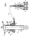
- a brake corrector 10 which, in the example illustrated, is formed integrally with a wheel cylinder of a drum brake (not shown) comprises a corrector body 11 which has a stepped bore 12.
- a control piston 14 is mounted with sealed sliding in a part 16, of enlarged diameter, of the stepped bore 12.
- the control piston 14 comprises an actuating rod 18 which bears on a piston 20 mounted with sliding watertight in a portion 22, of reduced diameter, of the stepped bore 12.
- the piston 20 is provided with a valve seat 24 intended to be closed, selectively, by a ball 26 cooperating with a rod 28 integral with the bottom of the 'stage bore 12.
- the wheel cylinder comprises a body 30 provided with a bore 32 in which are mounted, in sealed sliding, two actuating pistons 34,36.
- the corrector body 11 has a hydraulic inlet 38 intended to be connected to a source of pressurized hydraulic fluid, for example a master cylinder (not shown).
- the part 16 of the stage bore 12 is connected by a flexible pipe 40 to a fluid pressure sensor 42 mounted on a suspension element 44.
- the suspension element 44 comprises a damper 46 and a suspension spring 48 and it is intended to be mounted between the chassis and a suspended part of the vehicle (not shown).
- the fluid pressure sensor 42 which, in the example illustrated is a hydraulic sensor, comprises an annular collar 50 fixedly mounted on the damper 46 and has an annular groove 52 which is connected to the flexible pipe 40 by a passage 54.
- An annular piston 56 is sliding mounted tight in the annular groove 52 and comprises a tubular sleeve 58 which is arranged, with a slight clearance, around the damper 46.
- One end 60 of the suspension spring 48 comes to bear against an annular surface 62 of the annular piston 56.
- An increase in the vehicle load causes a corresponding variation in the force exerted by the suspension spring 48 on the annular piston 56, causing a variation in effective pressure of the annular groove 52.
- the displacement of the annular piston 56 causes a corresponding action on the control piston 14 which, via the actuating rod 18 and the piston 20, acts on the ball 26, thus controlling the flow of fluid between the master cylinder and the wheel cylinder 30.
- a reduction in the vehicle load acts in the opposite direction on the annular piston 56 so as to reduce the fluid pressure in the annular groove 52, causing the ball 26 to close on its seat 24.
- the suspension element 144 comprises a support element 162 which is slidably mounted around the damper 146 and which abuts against the annular piston 156 of the pressure sensor 142.
- the element of support 162 comprises an annular part 164, on which abuts an end 160 of the suspension spring 148, and a cup-shaped part 166 which surrounds one end 168 of the damper 146.
- the suspension element 144 further comprises , a sleeve 170 of elastomeric material which is arranged around a rod of the piston 172 of the shock absorber 46 and one end of which 174 is fixedly mounted on a support plate 176 integral with the chassis 178 of the vehicle.
- the sleeve 170 has a length such that, when the vehicle on which the device is mounted is empty, the end 180 does not come to bear against the support element 162. Then, only the force of the suspension spring 148 is transmitted to the annular piston 156. If the vehicle load increases, the damper 146 is compressed and the end 180 of the sleeve 170 abuts against the part 166 of the support element 162 to exert an additional force on the annular piston 156.
- the sleeve 170 has annular grooves 182 which ensure progressive deformation of the sleeve 170 when the load of the vehicle increases. The force applied to the annular piston 156 by the combination of the suspension spring 148 and the sleeve 170 better reflects the load of the vehicle.
- the fluidic sensor could be a pneumatic sensor, which would require an adaptation of the shape and dimensions of the annular piston 56, 156 and of the corrector piston 14, as is well known to those skilled in the art.
- the corrector sensor according to the invention has, among other advantages, that of using a pre-existing shock absorber in the vehicle as a support, which makes it possible to avoid the use of a particular support for this sensor.
Landscapes
- Engineering & Computer Science (AREA)
- Mechanical Engineering (AREA)
- Transportation (AREA)
- General Engineering & Computer Science (AREA)
- Hydraulic Control Valves For Brake Systems (AREA)
- Vehicle Body Suspensions (AREA)
Description
- La présente invention se rapporte aux correcteurs de freinage, et, plus particulièrement à un tel correcteur asservi à la charge d'un véhicule.
- Il est souhaitable, pour des raisons d'économie de place et de nombre de pièces, de relier un correcteur de freinage directement à la suspension d'un véhicule en vue de faire varier le freinage des roues du véhicule en fonction de sa charge.
- On connaît du document GB-A- 1 577 029 un correcteur de freinage asservi à la charge d'un véhicule, qui est disposé à une extrémité d'un ressort du suspension du véhicule et relié au ressort par un ensemble de cames de façon à faire varier la pression de freinage en fonction de la charge. Ce dispositif présente les inconvenients en ce qu'il comprend un nombre important de pièces, ce qui le rend onéreux et peu fiable.
- Pour pallier les inconvénients d'une liaison mécanique entre un correcteur et la suspension d'un véhicule on a proposé de relier le correcteur hydrauliquement à la suspension.
- On connaît du document FR-A-1 288 940 une installation de freinage pour véhicule dans laquelle un émetteur hydraulique est monté entre un ressort-lame de suspension et la châssis du véhicule, cet émetteur étant relié hydrauliquement à un correcteur de freinage de façon à faire fonctionner ce dernier en fonction de la charge du véhicule.
- Ce dispositif présente des inconvénients en ce qu'il est encombrant et peut gêner le déplacement de la suspension. De plus, ce dispositif ne se prête pas à être utilisé avec un ressort de suspension hélicoïdal.
- La présente invention a donc pour but de proposer un correcteur de freinage asservi à la charge d'un véhicule, qui est de construction simple, peu encombrant, fiable et d'installation facile.
- Le document JP-A 58 177 755 décrit un tel correcteur de freinage asservi à la charge d'un véhicule, dans lequel un recevoir élastique de pression est disposé entre un ressort de suspension et le châssis du véhicule.
- Un tel correcteur ne peut pas être mis en oeuvre dans un véhicule dont l'élément de suspension comprend un amortisseur à piston dont la tige est entourée d'un manchon élastique car la force reprise par ce manchon n'est pas prise en compte par le rése- voir. Il en résulterait alors une discontinuité nuisible dans la correction effectuée.
- La présente invention a donc pour but d'obvier à cet inconvénient.
- L'invention concerne donc un correcteur de freinage destiné à être asservi à la charge d'un véhicule ayant au moins un élément de suspension monté entre une plaque de support solidaire du chassis du véhicule et une partie suspendue du véhicule, l'élément de suspension comprenant coaxialement un amortisseur dont une extrémité est connectée à la partie suspendue, un ressort de suspension, une tige d'actionnement dont une extrémité est reliée au piston de l'amortisseur, et un manchon en matériau élastomère disposé autour de la tige dont l'autre extrémité ainsi que les extrémités correspondantes du ressort de suspension et du manchon sont montées fixes sur la plaque de support. Le correcteur est muni d'un capteur fluidique de pression et comprend un corps creusé d'un alésage dans lequel est monté à coulissement un piston agencé de façon à coopérer avec un élément de clapet pour commander un passage de fluide entre une entrée et une sortie du correcteur. Le capteur fluidique de pression comprend un piston annulaire monté à coulissement étanche dans un cylindre annulaire ménagé dans un collier annulaire monté fixe autour de l'amortisseur.
- Selon l'invention, l'autre extrémité du ressort de suspension vient en appui dans une partie annulaire d'un élément d'appui monté à coulissement autour de l'amortisseur et en butée contre le piston annulaire, cet élément d'appui ayant une partie centrale en forme de gobelet entourant l'autre extrémité de l'amortisseur en regard de l'autre extrémité du manchon, la partie centrale en forme de gobelet étant solidaire de la partie annulaire. D'autres caractéristiques et avantages de la présente invention ressortiront de la description suivante d'un mode de réalisation donné à titre d'exemple, faite en relation avec le dessin annexé, dans lequel:
- - la Figure 1 est une vue schématique en coupe longitudinale d'un correcteur de freinage asservi à la charge d'un véhicule, donnée à titre explicatif ; et
- - la Figure 2 est une vue en coupe longitudinale selon un mode de réalisation de l'invention.
- Comme représenté sur la figure 1, un correcteur de freinage 10 qui, dans l'exemple illustré, est formé intégralement avec un cylindre de roue d'un frein à tambour (non-représenté) comprend un corps de correcteur 11 qui comporte un alésage étagé 12. Un piston de commande 14 est monté à coulissement étanche dans une partie 16, de diamètre élargi, de l'alésage étagé 12. Le piston de commande 14 comporte une tige d'actionnement 18 qui prend appui sur un piston 20 monté à coulissement étanche dans une partie 22, de diamètre réduit, de l'alésage étagé 12. Le piston 20 est muni d'un siège de clapet 24 destiné à être fermé, sélectivement, par une bille 26 coopérant avec une tige 28 solidaire du fond de l'alésage étage 12. Le cylindre de roue comprend un corps 30 pourvu d'un alésage 32 dans lequel sont montés, à coulissement étanche, deux pistons d'actionnement 34,36. Le corps de correcteur 11 comporte une entrée hydraulique 38 destinée à être reliée à une source de fluide hydraulique sous pression, par exemple un maître-cylindre (non représenté).
- La partie 16 de l'alésage étage 12 est reliée par un tuyau flexible 40 à un capteur fluidique de pression 42 monté sur un élément de suspension 44. L'élément de suspension 44 comprend un amortisseur 46 et un ressort de suspension 48 et il est destiné à être monté entre le châssis et une partie suspendue, du véhicule (non-représentés).
- Le capteur de pression fluidique 42 qui , dans l'exemple illustré est un capteur hydraulique comprend un collier annulaire 50 monté fixe sur l'amortisseur 46 et présente une gorge annulaire 52 qui est reliée au tuyau flexible 40 par un passage 54. Un piston annulaire 56 est monté à coulissement étanche dans la gorge annulaire 52 et comporte un manchon tubulaire 58 qui est disposé, avec un faible jeu, autour de l'amortisseur 46. Une extrémité 60 du ressort de suspension 48 vient en appui contre une surface annulaire 62 du piston annulaire 56.
- Le fonctionnement du correcteur s'établit comme suit :
- Une augmentation de la charge du véhicule provoque une variation correspondante dans la force exercée par le ressort de suspension 48 sur le piston annulaire 56, entraînant une variation de pression effective de la gorge annulaire 52. Le déplacement du piston annulaire 56 provoque une action correspondante sur le piston de commande 14 qui, par l'intermédiaire de la tige d'actionnement 18 et du piston 20, agit sur la bille 26, controlant ainsi l'écoulement de fluide entre le maître-cylindre et le cylindre de roue 30. De manière analogue, une réduction de la charge du véhicule agit en sens inverse sur le piston annulaire 56 de façon à faire diminuer la pression de fluide dans la gorge annulaire 52, entraînant la fermeture de la bille 26 sur son siège 24.
- Sur la figure 2 est représenté un mode de réalisation selon l'invention de l'élément de suspension qui comprend un deuxième moyen pour transmettre l'effort de suspension au piston annulaire. Dans ce mode de réalisation l'élément de suspension 144 comprend un élément d'appui 162 qui est monté à coulissement autour de l'amortisseur 146 et qui est en butée contre le piston annulaire 156 du capteur de pression 142. L'élément d'appui 162 comprend une partie annulaire 164, sur laquelle vient en appui une extrémité 160 du ressort de suspension 148, et une partie 166 en forme de gobelet qui entoure une extrémité 168 de l'amortisseur 146. L'élément de suspension 144 comprend de plus, un manchon 170 en matériau élastomère qui est disposé autour d'une tige du piston 172 de l'amortisseur 46 et dont une extrémité 174 est montée fixe sur une plaque de support 176 solidaire avec le châssis 178 du véhicule.
- Le manchon 170 a une longueur telle que, quand le véhicule sur lequel le dispositif est monté est vide, l'extrémité 180 ne vient pas en appui contre l'élément d'appui 162. Alors, seul l'effort du ressort de suspension 148 est transmis au piston annulaire 156. Si la charge du véhicule augmente, l'amortisseur 146 est comprimé et l'extrémité 180 du manchon 170 vient en butée contre la partie 166 de l'élément d'appui 162 pour exercer une force supplémentaire sur le piston annulaire 156. Le manchon 170 comporte des rainures annulaires 182 qui assurent une déformation progressive du manchon 170 quand la charge du véhicule augmente. L'effort appliqué sur le piston annulaire 156 par la combinaison du ressort de suspension 148 et du manchon 170 refléte mieux la charge du véhicule.
- Il est envisagé que le capteur fluidique pourrait être un capteur pneumatique, ce qui nécessiterait une adaptation de la forme et des dimensions du piston annulaire 56, 156 et du piston 14 du correcteur, comme cela est bien connu de l'homme de métier.
- Le capteur du correcteur suivant l'invention présente, entre autres avantages, celui d'utiliser comme support un amortisseur préexistant dans le véhicule, ce qui permet d'éviter l'utilisation d'un support particulier pour ce capteur.
Claims (1)
- Correcteur de freinage (10) destiné à être asservi à la charge d'un véhicule ayant au moins un élément de suspension (144) monté entre une plaque de support (176) solidaire du châssis (178) du véhicule et une partie suspendue du véhicule, ledit élément de suspension (144) comprenant coaxialement un amortisseur (146) dont une extrémité est connectée à ladite partie suspendue, un ressort de suspension (148), une tige d'actionnement (172) dont une extrémité est reliée au piston dudit amortisseur (146), et un manchon (170) en matériau élastomère disposé autour de ladite tige (172) dont l'autre extrémité ainsi que les extrémités correspondantes dudit ressort de suspension (148) et dudit manchon (170) sont montées fixes sur ladite plaque de support (176), ledit correcteur (10) étant muni d'un capteur fluidique de pression (142), et comprenant un corps (11) creusé d'un alésage (12) dans lequel est monté à coulissement un piston (20) agencé de façon à coopérer avec un élément de clapet (26) pour commander un passage de fluide entre une entrée (38) et une sortie (32) du correcteur (10), ledit capteur fluidique de pression (142) comprenant un piston annulaire (156) monté à coulissement étanche dans un cylindre annulaire (150) ménagé dans un collier annulaire (150) monté fixe autour dudit amortisseur (146), caracteri- sé en ce que l'autre extrémité dudit ressort de suspension (148) vient en appui dans une partie annulaire (164) d'un élément d'appui (162) monté à coulissement autour dudit amortisseur (146) et en butée contre ledit piston annulaire (156), ledit élément d'appui (162) ayant une partie centrale (166) en forme de gobelet entourant l'autre extrémité dudit amortisseur (146) en regard de l'autre extrémité dudit manchon (170), ladite partie centrale (166) en forme de gobelet étant solidaire de ladite partie annulaire (164).
Applications Claiming Priority (2)
| Application Number | Priority Date | Filing Date | Title |
|---|---|---|---|
| FR8702538 | 1987-02-26 | ||
| FR8702538A FR2611628B1 (fr) | 1987-02-26 | 1987-02-26 | Correcteur de freinage asservi a la charge d'un vehicule |
Publications (2)
| Publication Number | Publication Date |
|---|---|
| EP0283328A1 EP0283328A1 (fr) | 1988-09-21 |
| EP0283328B1 true EP0283328B1 (fr) | 1990-04-04 |
Family
ID=9348330
Family Applications (1)
| Application Number | Title | Priority Date | Filing Date |
|---|---|---|---|
| EP88400172A Expired - Lifetime EP0283328B1 (fr) | 1987-02-26 | 1988-01-27 | Correcteur de freinage asservi à la charge d'un véhicule |
Country Status (9)
| Country | Link |
|---|---|
| US (1) | US4824180A (fr) |
| EP (1) | EP0283328B1 (fr) |
| JP (1) | JP2657922B2 (fr) |
| KR (1) | KR880009830A (fr) |
| BR (1) | BR8800769A (fr) |
| DE (1) | DE3860070D1 (fr) |
| ES (1) | ES2013782B3 (fr) |
| FR (1) | FR2611628B1 (fr) |
| YU (1) | YU25588A (fr) |
Families Citing this family (62)
| Publication number | Priority date | Publication date | Assignee | Title |
|---|---|---|---|---|
| FR2629412B1 (fr) * | 1988-03-30 | 1991-10-25 | Bendix France | Correcteur de freinage asservi a la charge d'un vehicule en fonction de l'assiette de ce dernier |
| EP0448589B1 (fr) * | 1988-12-15 | 1993-06-16 | Automotive Products Public Limited Company | Systemes de freinage pour vehicules |
| DE3911601A1 (de) * | 1989-04-08 | 1990-10-11 | Vdo Schindling | Lastsensor fuer ein kraftfahrzeug |
| FR2649046B1 (fr) * | 1989-06-28 | 1991-09-13 | Bendix France | Piece d'appui pour ressort de suspension |
| FR2651184B1 (fr) * | 1989-08-31 | 1991-10-25 | Bendix France | Piece d'appui pour element de suspension. |
| JPH03104760A (ja) * | 1989-09-19 | 1991-05-01 | Tokico Ltd | 荷重検知式液圧制御装置 |
| FR2653880B1 (fr) * | 1989-10-31 | 1992-01-17 | Bendix France | Capteur de charge instantanee d'un vehicule automobile. |
| FR2655003B1 (fr) * | 1989-11-30 | 1992-02-21 | Bendix France | Circuit de commande d'un correcteur de freinage a commande fluidique. |
| GB9001565D0 (en) * | 1990-01-23 | 1990-03-21 | Gen Motors France | Disc brake |
| FR2660269B1 (fr) * | 1990-03-29 | 1992-06-12 | Bendix Europ Services Tech | Compensateur de freinage a valve additionnelle. |
| FR2751930B1 (fr) * | 1996-08-05 | 1998-09-18 | Bosch Syst Freinage | Systeme de freinage assiste a reaction asservie |
| US5877677A (en) * | 1996-11-22 | 1999-03-02 | Christopher Shoulders, L.L.C. | Control of air bag activation in vehicles by occupancy weight |
| US6658924B2 (en) | 1999-01-22 | 2003-12-09 | The Yokohama Rubber Co., Ltd. | Method for measuring dynamic characteristics of wheel of vehicle |
| JP4086397B2 (ja) * | 1999-01-22 | 2008-05-14 | 横浜ゴム株式会社 | 車輪の動荷重特性計測装置 |
| DE10144163C1 (de) * | 2001-09-08 | 2003-04-10 | Zf Sachs Ag | Federbein mit höheneinstellbarem Federteller |
| DE10301546B3 (de) * | 2003-01-16 | 2004-05-06 | Zf Sachs Ag | Federbein mit höhenverstellbarem Federteller |
| NL1026610C2 (nl) * | 2004-07-08 | 2006-01-10 | Wp Suspension B V | Schokbreker met drukondersteunde verstelling. |
| US20070017758A1 (en) * | 2005-07-20 | 2007-01-25 | Or Siu W | Magnetorheological damper and use thereof |
| JP4563307B2 (ja) * | 2005-11-29 | 2010-10-13 | 株式会社ショーワ | 油圧緩衝器の懸架スプリング調整装置 |
| JP4669389B2 (ja) * | 2005-12-22 | 2011-04-13 | 株式会社ショーワ | 油圧緩衝器の懸架スプリング調整装置 |
| DE102007044538A1 (de) * | 2007-09-11 | 2009-03-12 | Wohlfarth, Klaus | Einrichtung zur Höhenverstellung |
| DE102007043830A1 (de) | 2007-09-13 | 2009-04-02 | Lozonschi, Lucian, Madison | Herzklappenstent |
| EP3300695B1 (fr) | 2009-12-08 | 2023-05-24 | Avalon Medical Ltd. | Dispositif et système de remplacement de valvule mitrale par transcathéter |
| GB2476807B (en) * | 2010-01-08 | 2012-10-31 | David Andrew Gale | A vehicle |
| EP2741711B1 (fr) | 2011-08-11 | 2018-05-30 | Tendyne Holdings, Inc. | Améliorations apportées à des valves prothétiques et inventions associées |
| US9827092B2 (en) | 2011-12-16 | 2017-11-28 | Tendyne Holdings, Inc. | Tethers for prosthetic mitral valve |
| WO2014022124A1 (fr) | 2012-07-28 | 2014-02-06 | Tendyne Holdings, Inc. | Conceptions multi-composantes améliorées pour dispositif de récupération de valve cardiaque, structures d'étanchéité et ensemble stent |
| WO2014021905A1 (fr) | 2012-07-30 | 2014-02-06 | Tendyne Holdings, Inc. | Systèmes et procédés d'administration améliorée pour valvules prothétiques transcathéter |
| US10463489B2 (en) | 2013-04-02 | 2019-11-05 | Tendyne Holdings, Inc. | Prosthetic heart valve and systems and methods for delivering the same |
| US11224510B2 (en) | 2013-04-02 | 2022-01-18 | Tendyne Holdings, Inc. | Prosthetic heart valve and systems and methods for delivering the same |
| US9486306B2 (en) | 2013-04-02 | 2016-11-08 | Tendyne Holdings, Inc. | Inflatable annular sealing device for prosthetic mitral valve |
| US10478293B2 (en) | 2013-04-04 | 2019-11-19 | Tendyne Holdings, Inc. | Retrieval and repositioning system for prosthetic heart valve |
| US9610159B2 (en) | 2013-05-30 | 2017-04-04 | Tendyne Holdings, Inc. | Structural members for prosthetic mitral valves |
| CN108814772B (zh) | 2013-06-25 | 2020-09-08 | 坦迪尼控股股份有限公司 | 用于假体心脏瓣膜的血栓管理和结构顺应特征 |
| CN105555231B (zh) | 2013-08-01 | 2018-02-09 | 坦迪尼控股股份有限公司 | 心外膜锚固装置和方法 |
| EP3046783B1 (fr) * | 2013-09-17 | 2019-04-17 | Sistemi Sospensioni S.p.A. | Jambe de force pour véhicule automobile comprenant un dispositif de réglage de hauteur |
| WO2015058039A1 (fr) | 2013-10-17 | 2015-04-23 | Robert Vidlund | Appareil et procedes d'alignement et de deploiement de dispositifs intracardiaques |
| ES2773255T3 (es) | 2013-10-28 | 2020-07-10 | Tendyne Holdings Inc | Válvula cardiaca protésica y sistemas para suministrar la misma |
| US9526611B2 (en) | 2013-10-29 | 2016-12-27 | Tendyne Holdings, Inc. | Apparatus and methods for delivery of transcatheter prosthetic valves |
| WO2015120122A2 (fr) | 2014-02-05 | 2015-08-13 | Robert Vidlund | Appareil et procédés pour la mise en place d'une valve mitrale prothétique par l'artère fémorale |
| WO2016112085A2 (fr) | 2015-01-07 | 2016-07-14 | Mark Christianson | Prothèses de valvules mitrales et appareil et procédés de mise en place associé |
| US9986993B2 (en) | 2014-02-11 | 2018-06-05 | Tendyne Holdings, Inc. | Adjustable tether and epicardial pad system for prosthetic heart valve |
| CA2937566C (fr) | 2014-03-10 | 2023-09-05 | Tendyne Holdings, Inc. | Dispositifs et procedes de positionnement et de controle de charge de cable d'attache pour valvule mitrale prothetique |
| JP6256168B2 (ja) * | 2014-04-14 | 2018-01-10 | 日本精工株式会社 | 荷重センサ付き軸受装置 |
| CA2975294A1 (fr) | 2015-02-05 | 2016-08-11 | Tendyne Holdings, Inc. | Tampons epicardiques expansibles et dispositifs et procedes d'administration de ceux-ci |
| FR3034711B1 (fr) * | 2015-04-07 | 2017-04-28 | Peugeot Citroen Automobiles Sa | Systeme de butee d’attaque pour la suspension d'un vehicule mesurant la charge de ce vehicule |
| EP3695810B1 (fr) | 2015-04-16 | 2022-05-18 | Tendyne Holdings, Inc. | Appareils pour la récupération des valves prothétiques transcathéter |
| US10327894B2 (en) | 2015-09-18 | 2019-06-25 | Tendyne Holdings, Inc. | Methods for delivery of prosthetic mitral valves |
| EP3632380B1 (fr) | 2015-12-03 | 2024-01-24 | Tendyne Holdings, Inc. | Attributs de cadre pour valvules mitrales prothétiques |
| CA3006010C (fr) | 2015-12-28 | 2023-09-26 | Tendyne Holdings, Inc. | Fermetures de poche auriculaire pour valvules cardiaques prothetiques |
| US10470877B2 (en) | 2016-05-03 | 2019-11-12 | Tendyne Holdings, Inc. | Apparatus and methods for anterior valve leaflet management |
| US11039921B2 (en) | 2016-06-13 | 2021-06-22 | Tendyne Holdings, Inc. | Sequential delivery of two-part prosthetic mitral valve |
| US11090157B2 (en) | 2016-06-30 | 2021-08-17 | Tendyne Holdings, Inc. | Prosthetic heart valves and apparatus and methods for delivery of same |
| EP3484411A1 (fr) | 2016-07-12 | 2019-05-22 | Tendyne Holdings, Inc. | Appareil et procédés de récupération transseptale de valvules cardiaques prothétiques |
| JP7216066B2 (ja) | 2017-07-13 | 2023-01-31 | テンダイン ホールディングス,インコーポレイテッド | 人工心臓弁とその送達のための装置および方法 |
| AU2018323900A1 (en) | 2017-08-28 | 2020-02-27 | Tendyne Holdings, Inc. | Prosthetic heart valves with tether coupling features |
| FR3075104B1 (fr) * | 2017-12-20 | 2020-02-28 | Renault S.A.S. | Dispositif de support de ressort |
| EP3831343B1 (fr) | 2019-12-05 | 2024-01-31 | Tendyne Holdings, Inc. | Ancrage tressé pour valvule mitrale |
| US11648114B2 (en) | 2019-12-20 | 2023-05-16 | Tendyne Holdings, Inc. | Distally loaded sheath and loading funnel |
| US11951002B2 (en) | 2020-03-30 | 2024-04-09 | Tendyne Holdings, Inc. | Apparatus and methods for valve and tether fixation |
| WO2022039853A1 (fr) | 2020-08-19 | 2022-02-24 | Tendyne Holdings, Inc. | Tampon apical entièrement transseptal doté d'une poulie pour la mise sous tension |
| CN217603249U (zh) * | 2021-12-30 | 2022-10-18 | 比亚迪股份有限公司 | 减振器总成及具有其的车辆 |
Family Cites Families (14)
| Publication number | Priority date | Publication date | Assignee | Title |
|---|---|---|---|---|
| US2574426A (en) * | 1948-07-16 | 1951-11-06 | Dunlop Rubber Co | Braking system for aircraft |
| DE1430330A1 (de) * | 1960-10-06 | 1968-11-14 | Teves Gmbh Alfred | Bremskraftregler |
| GB1107918A (en) * | 1965-09-28 | 1968-03-27 | Automotive Prod Co Ltd | Improvements in or relating to internal shoe drum brakes for vehicles |
| US3628810A (en) * | 1970-07-29 | 1971-12-21 | Ford Motor Co | Level adjustment for motor vehicles |
| US4040674A (en) * | 1976-06-07 | 1977-08-09 | Wabco Westinghouse | Vehicle load force proportioning device |
| US4159105A (en) * | 1978-02-21 | 1979-06-26 | Bouvier Robert A | Shock absorber with adjustable spring load |
| DE3120432A1 (de) * | 1981-05-22 | 1983-01-13 | Alfred Teves Gmbh, 6000 Frankfurt | Lastabhaengige bremsdrucksteuervorrichtung fuer fahrzeugbremsanlagen |
| JPS58177755A (ja) * | 1982-04-10 | 1983-10-18 | Mitsubishi Motors Corp | 積載荷重応答液圧制御装置 |
| DE3224295A1 (de) * | 1982-06-28 | 1983-12-29 | Vdo Adolf Schindling Ag, 6000 Frankfurt | Steuerdruckgeber |
| JPH0235009B2 (ja) * | 1982-08-31 | 1990-08-08 | Koshuha Netsuren Kk | Waakunokinitsukanetsuhohooyobyudokanetsusochi |
| JPS59202964A (ja) * | 1983-04-30 | 1984-11-16 | Nissan Motor Co Ltd | ブレ−キ液圧制御機構 |
| FR2562017B1 (fr) * | 1984-03-28 | 1986-07-18 | Dba | Dispositif de securite sur correcteur de freinage |
| JPS6198604A (ja) * | 1984-10-18 | 1986-05-16 | Toyota Motor Corp | シヨツクアブソ−バの取付け構造 |
| GB8513526D0 (en) * | 1985-05-29 | 1985-07-03 | Lucas Ind Plc | Suspension strut assembly |
-
1987
- 1987-02-26 FR FR8702538A patent/FR2611628B1/fr not_active Expired - Lifetime
-
1988
- 1988-01-27 DE DE8888400172T patent/DE3860070D1/de not_active Expired - Lifetime
- 1988-01-27 EP EP88400172A patent/EP0283328B1/fr not_active Expired - Lifetime
- 1988-01-27 ES ES88400172T patent/ES2013782B3/es not_active Expired - Lifetime
- 1988-02-03 KR KR1019880000986A patent/KR880009830A/ko not_active Ceased
- 1988-02-08 US US07/153,618 patent/US4824180A/en not_active Expired - Fee Related
- 1988-02-10 YU YU00255/88A patent/YU25588A/xx unknown
- 1988-02-24 BR BR8800769A patent/BR8800769A/pt not_active IP Right Cessation
- 1988-02-26 JP JP63042408A patent/JP2657922B2/ja not_active Expired - Fee Related
Also Published As
| Publication number | Publication date |
|---|---|
| FR2611628B1 (fr) | 1990-11-30 |
| KR880009830A (ko) | 1988-10-05 |
| FR2611628A1 (fr) | 1988-09-09 |
| ES2013782B3 (es) | 1990-06-01 |
| JPH01218948A (ja) | 1989-09-01 |
| EP0283328A1 (fr) | 1988-09-21 |
| US4824180A (en) | 1989-04-25 |
| DE3860070D1 (de) | 1990-05-10 |
| BR8800769A (pt) | 1988-10-04 |
| JP2657922B2 (ja) | 1997-09-30 |
| YU25588A (en) | 1990-06-30 |
Similar Documents
| Publication | Publication Date | Title |
|---|---|---|
| EP0283328B1 (fr) | Correcteur de freinage asservi à la charge d'un véhicule | |
| EP1595085B1 (fr) | Dispositif de transmission de couple pour vehicule automobile | |
| FR2773599A1 (fr) | Ressort hydropneumatique | |
| EP0214000B1 (fr) | Compensateur automatique d'usure pour embrayage de véhicule automobile | |
| FR2545055A1 (fr) | Amplificateur de force hydraulique, notamment pour systeme de freinage de vehicule automobile | |
| EP1600347B1 (fr) | Simulateur d'actionnement de frein, maître-cylindre pour frein de vehicule automobile, et procede de commande de ce simulateur | |
| EP0565402B1 (fr) | Tendeur automatique pour courroie, notamment pour courroie de transmission synchrone, comme une courroie de distribution de moteur thermique | |
| FR2830586A1 (fr) | Embrayage, en particulier pour vehicule automobile, a commande pneumatique | |
| EP0335764B1 (fr) | Correcteur de freinage asservi à la charge d'un véhicule en fonction de l'assiette de ce dernier | |
| EP0053528B1 (fr) | Correcteur de pression de freinage | |
| FR2492923A1 (fr) | Dispositif compensateur de l'usure d'un embrayage de vehicule | |
| FR2509805A1 (fr) | Amplificateur de force hydraulique | |
| EP0262999B1 (fr) | Correcteur de freinage asservi à la charge d'un véhicule | |
| FR2559105A1 (fr) | Dispositif d'actionnement d'embrayage | |
| EP0041020B1 (fr) | Dispositif de dosage pour une installation de freinage pour véhicule | |
| FR2571445A1 (fr) | Maitre-cylindre pour systeme hyraulique | |
| EP0261011B2 (fr) | Correcteur de freinage asservi à la charge d'un véhicule | |
| FR2593453A1 (fr) | Amplificateur hydraulique de freinage. | |
| FR2492757A2 (fr) | Unite de freinage assiste pour vehicules automobiles | |
| BE501958A (fr) | ||
| FR2466374A1 (fr) | Regulateur de force de freinage reglable automatiquement en fonction de la charge | |
| FR2829737A1 (fr) | Maitre-cylindre tandem pour systemes de freinage electrohydraulique | |
| FR2495079A1 (fr) | Correcteur de pression de freinage | |
| EP0874169A1 (fr) | Dispositif de rattrapage automatique de jeu d'une commande par câble, application à la commande de l'embrayage ou de frein d'un véhicule | |
| FR2579156A1 (fr) | Soupape de frein |
Legal Events
| Date | Code | Title | Description |
|---|---|---|---|
| PUAI | Public reference made under article 153(3) epc to a published international application that has entered the european phase |
Free format text: ORIGINAL CODE: 0009012 |
|
| 17P | Request for examination filed |
Effective date: 19880130 |
|
| AK | Designated contracting states |
Kind code of ref document: A1 Designated state(s): DE ES GB IT |
|
| 17Q | First examination report despatched |
Effective date: 19890628 |
|
| GRAA | (expected) grant |
Free format text: ORIGINAL CODE: 0009210 |
|
| AK | Designated contracting states |
Kind code of ref document: B1 Designated state(s): DE ES GB IT |
|
| GBT | Gb: translation of ep patent filed (gb section 77(6)(a)/1977) | ||
| ITF | It: translation for a ep patent filed | ||
| REF | Corresponds to: |
Ref document number: 3860070 Country of ref document: DE Date of ref document: 19900510 |
|
| PLBE | No opposition filed within time limit |
Free format text: ORIGINAL CODE: 0009261 |
|
| STAA | Information on the status of an ep patent application or granted ep patent |
Free format text: STATUS: NO OPPOSITION FILED WITHIN TIME LIMIT |
|
| 26N | No opposition filed | ||
| ITTA | It: last paid annual fee | ||
| REG | Reference to a national code |
Ref country code: GB Ref legal event code: IF02 |
|
| PGFP | Annual fee paid to national office [announced via postgrant information from national office to epo] |
Ref country code: GB Payment date: 20031231 Year of fee payment: 17 |
|
| PGFP | Annual fee paid to national office [announced via postgrant information from national office to epo] |
Ref country code: ES Payment date: 20040129 Year of fee payment: 17 |
|
| PGFP | Annual fee paid to national office [announced via postgrant information from national office to epo] |
Ref country code: DE Payment date: 20040310 Year of fee payment: 17 |
|
| PG25 | Lapsed in a contracting state [announced via postgrant information from national office to epo] |
Ref country code: IT Free format text: LAPSE BECAUSE OF NON-PAYMENT OF DUE FEES;WARNING: LAPSES OF ITALIAN PATENTS WITH EFFECTIVE DATE BEFORE 2007 MAY HAVE OCCURRED AT ANY TIME BEFORE 2007. THE CORRECT EFFECTIVE DATE MAY BE DIFFERENT FROM THE ONE RECORDED. Effective date: 20050127 Ref country code: GB Free format text: LAPSE BECAUSE OF NON-PAYMENT OF DUE FEES Effective date: 20050127 |
|
| PG25 | Lapsed in a contracting state [announced via postgrant information from national office to epo] |
Ref country code: ES Free format text: LAPSE BECAUSE OF NON-PAYMENT OF DUE FEES Effective date: 20050128 |
|
| PG25 | Lapsed in a contracting state [announced via postgrant information from national office to epo] |
Ref country code: DE Free format text: LAPSE BECAUSE OF NON-PAYMENT OF DUE FEES Effective date: 20050802 |
|
| GBPC | Gb: european patent ceased through non-payment of renewal fee |
Effective date: 20050127 |
|
| REG | Reference to a national code |
Ref country code: ES Ref legal event code: FD2A Effective date: 20050128 |