EP0283335B1 - Bague d'étanchéité - Google Patents
Bague d'étanchéité Download PDFInfo
- Publication number
- EP0283335B1 EP0283335B1 EP19880400296 EP88400296A EP0283335B1 EP 0283335 B1 EP0283335 B1 EP 0283335B1 EP 19880400296 EP19880400296 EP 19880400296 EP 88400296 A EP88400296 A EP 88400296A EP 0283335 B1 EP0283335 B1 EP 0283335B1
- Authority
- EP
- European Patent Office
- Prior art keywords
- ring
- membrane
- bellows
- hermetic
- friction ring
- Prior art date
- Legal status (The legal status is an assumption and is not a legal conclusion. Google has not performed a legal analysis and makes no representation as to the accuracy of the status listed.)
- Expired - Lifetime
Links
Images
Classifications
-
- F—MECHANICAL ENGINEERING; LIGHTING; HEATING; WEAPONS; BLASTING
- F16—ENGINEERING ELEMENTS AND UNITS; GENERAL MEASURES FOR PRODUCING AND MAINTAINING EFFECTIVE FUNCTIONING OF MACHINES OR INSTALLATIONS; THERMAL INSULATION IN GENERAL
- F16J—PISTONS; CYLINDERS; SEALINGS
- F16J15/00—Sealings
- F16J15/16—Sealings between relatively-moving surfaces
- F16J15/34—Sealings between relatively-moving surfaces with slip-ring pressed against a more or less radial face on one member
- F16J15/36—Sealings between relatively-moving surfaces with slip-ring pressed against a more or less radial face on one member connected by a diaphragm or bellow to the other member
Definitions
- the present invention relates to a sealing ring intended to form with a counter ring a sealing device between a rotary shaft and a fixed part, applicable in particular to centrifugal pumps, and comprising, in a conventional manner, a friction ring, a flexible membrane comprising at one end a veil made integral with the friction ring by an assembly box and a collar tightened by a ring on the part to be sealed, a spacer piece on which the assembly box is crimped and a return member mounted between the spacer and the ring to separate the two ends of the membrane from each other and, in addition, an elastic external bellows which covers it over practically its entire length, the space between the inner membrane and said outer bellows being partially filled with a liquid or neutral grease.
- the external bellows form with the flexible membrane a sealed cavity in which the filling liquid can be pressurized by elastic deformation of said bellows, under the effect of the pressure of the fluid to be sealed.
- the sealing ring shown is mounted on the rotary shaft of a machine such as a centrifugal pump. It includes a friction ring 1 and the friction face is in contact with the counter ring 2 fixed to the casing 3 of the pump.
- the friction ring 1 is made integral with a web 4 of a membrane of elastic material 5 by an assembly box 6 crimped on the ring 1.
- a spacer piece 7 is mounted inside the box 6 of so as to lock in position the web 4 of the elastic membrane against the friction ring 1.
- the elastic membrane comprises a part 8 in the form of a collar clamped on the shaft by a ring 9.
- the spacer piece 7 and the clamping ring 9 each have a housing which face each other and serve as support for the ends d 'a helical compression spring 10.
- An external elastic bellows 11 covers the ring which has just been described by applying closely, by its end 12 in the form of a veil to the friction ring 1, by its central wall, on the assembly housing 6 and, by its rear part 13, on the clamping ring 8.
- the narrow application of the bellows 11 on the sealing ring is ensured by rings 14, 15.
- the interior space 16 between the membranes 5 and 11 is partially filled with a neutral liquid or grease ensuring the useful back pressure on the rubbing face between the friction ring 1 and the counter ring 2.
- the amount of viscous fluid introduced into space 16 may vary between 1/2 and 9/10 of the available capacity. The greater the relative quantity introduced, the more the action of the pressure of the fluid on the outer membrane 11 is reflected on the inner membrane 5 in order to apply more strongly the friction ring 1 to the contrabug 2. It is thus possible to dose precisely this action to achieve a seal whose sealing is perfect for a wide range of pressure to be sealed and at the same time ensuring energy consumption with minimum friction guaranteeing a long operating time.
- the invention is applicable to any type of sealing ring, the shape of the external bellows being adapted to those of the external faces of this ring.
Landscapes
- Engineering & Computer Science (AREA)
- General Engineering & Computer Science (AREA)
- Mechanical Engineering (AREA)
- Mechanical Sealing (AREA)
- Structures Of Non-Positive Displacement Pumps (AREA)
Description
- La présente invention concerne une bague d'étanchéité destinée à former avec une contre-bague un dispositif d'étanchéité entre un arbre rotatif et une partie fixe, applicable en particulier aux pompes centrifuges, et comprenant, de façon classique, une bague de frottement, une membrane souple comportant à une extrémité un voile rendu solidaire de la bague de frottement par un boîtier d'assemblage et un collet serré par un anneau sur la pièce à étancher, une pièce d'entretoise sur laquelle est serti le boîtier d'assemblage et un organe de rappel monté entre la pièce d'entretoise et l'anneau pour écarter l'une de l'autre les deux extrémités de la membrane et, en outre, un soufflet extérieur élastique qui la recouvre sur pratiquement toute sa longueur, l'espace compris entre la membrane intérieure et ledit soufflet extérieur étant rempli partiellement d'un liquide ou d'une graisse neutre.
- L'utilisation de ces bagues d'étanchéité avec les pompes destinées à traiter des produits alimentaires pose de graves problèmes d'hygiène. En effet, des particules de matières putrescibles peuvent se loger dans les interstices existant entre les différentes pièces de ces bagues et conduire à des proliférations de bactéries et provoquer de dangereuses altérations des produits traités.
- Pour éviter des inconvénients on peut prévoir de recouvrir la bague d'étanchéité sur pratiquement toute sa longueur d'un soufflet élastique.
- La présence de ce soufflet extérieur isole, comme on le désire, l'espace intérieur de la bague du liquide extérieur mais celui-ci ne participe alors plus à la pression qu'il exerce habituellement sur la face de contact entre la bague de frottement et la contre-bague.
- Cette absence de contre-pression sur la face frottante nuit à l'étanchéité et on a déjà proposé, par exemple dans US-A 4342.538, de remplir l'espace compris entre la membrane intérieure de la bague et le soufflet extérieur d'un liquide de remplissage ou une graisse neutres, tels que glycérine graisse vaseline.
- Mais pour maintenir entre la bague de frottement et la contre-bague un contact frottant assurant l'étanchéité dynamique dans les meilleures conditions, il est nécessaire, et c'est ce que prévoit l'invention, que le soufflet extérieur forme avec la membrane souple une cavité étanche dans laquelle le liquide de remplissage peut-être mis sous pression par déformation élastique du dit soufflet, sous l'effet de la pression du fluide à étancher.
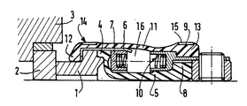
- A titre nullement limitatif, on a représenté au dessin annexé un example de réalisation de l'invention, dessin sur lequel la figure unique est une vue en coupe axiale d'une bague selon l'invention à l'état libre.
- La bague d'étanchéité représentée est montée sur l'arbre rotatif d'une machine telle qu'une pompe centrifuge. Elle comprend une bague de frottement 1 sont la face frottante est en contact de la contre-bague 2 fixée au carter 3 de la pompe. La bague de frottement 1 est rendue solidaire d'un voile 4 d'une membrane en matière élastique 5 par un boîtier d'assemblage 6 serti sur la bague 1. Une pièce d'entretoise 7 est montée à l'intérieur du boîtier 6 de façon à bloquer en position le voile 4 de la membrane élastique contre la bague de frottement 1.
- La membrane élastique comporte une partie 8 en forme de collet serrée sur l'arbre par un anneau 9. La pièce d'entretoise 7 et l'anneau de serrage 9 présentent chacun un logement qui se font face et servent d'appui aux extrémités d'un ressort de compression hélicoïdal 10.
- Un soufflet élastique 11 extérieur recouvre la bague qui vient d'être décrite en s'appliquant étroitement, par son extrémité 12 en forme de voile sur la bague de frottement 1, par sa paroi centrale, sur le boîtier d'assemblage 6 et, par sa partie arrière 13, sur l'anneau de serrage 8. L'application étroite du soufflet 11 sur la bague d'étanchéité est assurée par des anneaux 14, 15.
- L'espace intérieur 16 entre les membranes 5 et 11 est rempli partiellement d'un liquide ou d'une graisse neutre assurant la contre-pression utile sur la face frottante entre la bague de frottement 1 et la contre-bague 2. La quantité du fluide visqueux introduit dans l'espace 16 peur varier entre le 1/2 et les 9/10 de la capacité disponible. Plus la quantité relative introduite est importante et plus l'action de la pression du fluide sur la membrane extérieure 11 se répercute sur la membrane intérieure 5 pour appliquer plus fortement l'anneau de frottement 1 sur la contreba- gue 2. On peut ainsi doser précisément cette action pour réaliser une garniture dont l'étanchéité est parfaite pour une large gamme de pression à étancher et en même temps assurer une consommation d'énergie au frottement minimum garantissant une longue durée de fonctionnement.
- Bien entendu l'invention est applicable à tout type de bague d'étanchéité, la forme du soufflet extérieur étant adaptée à celles des faces extérieures de cette bague.
Claims (2)
Applications Claiming Priority (2)
| Application Number | Priority Date | Filing Date | Title |
|---|---|---|---|
| FR8701609A FR2610688B1 (fr) | 1987-02-10 | 1987-02-10 | Bague d'etancheite |
| FR8701609 | 1987-02-10 |
Publications (2)
| Publication Number | Publication Date |
|---|---|
| EP0283335A1 EP0283335A1 (fr) | 1988-09-21 |
| EP0283335B1 true EP0283335B1 (fr) | 1990-08-22 |
Family
ID=9347752
Family Applications (1)
| Application Number | Title | Priority Date | Filing Date |
|---|---|---|---|
| EP19880400296 Expired - Lifetime EP0283335B1 (fr) | 1987-02-10 | 1988-02-09 | Bague d'étanchéité |
Country Status (4)
| Country | Link |
|---|---|
| EP (1) | EP0283335B1 (fr) |
| DE (1) | DE3860469D1 (fr) |
| ES (1) | ES2018075B3 (fr) |
| FR (1) | FR2610688B1 (fr) |
Families Citing this family (2)
| Publication number | Priority date | Publication date | Assignee | Title |
|---|---|---|---|---|
| SE531210C2 (sv) | 2007-05-07 | 2009-01-20 | Roplan Internat Ab | Mekanisk tätningsanordning samt pump |
| CN113847249A (zh) * | 2021-10-13 | 2021-12-28 | 宁夏金泉泵业有限责任公司 | 离心式水泵 |
Family Cites Families (4)
| Publication number | Priority date | Publication date | Assignee | Title |
|---|---|---|---|---|
| US2806720A (en) * | 1954-02-04 | 1957-09-17 | Muskegon Piston Ring Co Inc | Seal |
| US2899219A (en) * | 1954-09-20 | 1959-08-11 | payne | |
| US4342538A (en) * | 1980-06-02 | 1982-08-03 | The Gorman-Rupp Company | Face-type shaft seal |
| GB2085982B (en) * | 1980-10-14 | 1984-03-14 | Borg Warner | Mechanical seal assembly |
-
1987
- 1987-02-10 FR FR8701609A patent/FR2610688B1/fr not_active Expired - Lifetime
-
1988
- 1988-02-09 DE DE8888400296T patent/DE3860469D1/de not_active Expired - Lifetime
- 1988-02-09 EP EP19880400296 patent/EP0283335B1/fr not_active Expired - Lifetime
- 1988-02-09 ES ES88400296T patent/ES2018075B3/es not_active Expired - Lifetime
Also Published As
| Publication number | Publication date |
|---|---|
| FR2610688B1 (fr) | 1990-06-01 |
| DE3860469D1 (de) | 1990-09-27 |
| EP0283335A1 (fr) | 1988-09-21 |
| FR2610688A1 (fr) | 1988-08-12 |
| ES2018075B3 (es) | 1991-03-16 |
Similar Documents
| Publication | Publication Date | Title |
|---|---|---|
| FR2616191A1 (fr) | Joint rotatif etanche a soufflets | |
| EP0978673A1 (fr) | Agencement d'étanchéité à réglage automatique de jeu | |
| EP4076753B1 (fr) | Conteneur à étanchéité renforcée | |
| EP1251617B1 (fr) | Joint d'étanchéité pour cables | |
| EP0283335B1 (fr) | Bague d'étanchéité | |
| CH324489A (fr) | Dispositif d'étanchéité destiné à être disposé entre deux pièces mécaniques coaxiales en rotation relative | |
| FR3087503A1 (fr) | Pompe peristaltique etanche pour appareil electromenager | |
| FR2793081A1 (fr) | Dispositif d'etancheite du type presse-garniture pour un cable | |
| FR2712648A1 (fr) | Dispositif d'accouplement élastique pour arbres tournants. | |
| FR1464434A (fr) | Joint pour arbres, notamment pour arbres oscillants | |
| FR2523233A1 (fr) | Dispositif pour bloquer la bague interieure d'un roulement sur un arbre rotatif | |
| FR2643968A1 (fr) | Passage etanche d'un arbre a travers l'evidement d'un palier | |
| FR2620775A1 (fr) | Ensemble de machine a membrane | |
| EP3966477B1 (fr) | Garniture d'etancheite compacte pour assurer l'etancheite entre un arbre rotatif et un corps stationnaire d'une machine | |
| FR2623589A1 (fr) | Garniture d'etancheite | |
| FR2607898A1 (fr) | Suppresseur d'a-coups dans un circuit de fluide | |
| FR2568655A1 (fr) | Joint a fluide hydraulique, machine a engrenage et plaque de compression pour cette machine | |
| EP0328433B1 (fr) | Dispositif d'étanchéité à frottement latéral | |
| FR2520469A1 (fr) | Joint frontal mecanique | |
| CH373933A (fr) | Dispositif d'étanchéité rotatif | |
| FR2645235A1 (fr) | Ensemble d'etancheite, et actionneur rotatif commande par un fluide et le comportant | |
| FR2459414A1 (fr) | Perfectionnements apportes aux presse-etoupe | |
| FR2515769A1 (fr) | Perfectionnements aux joints d'etancheite a levre | |
| CH357901A (fr) | Vibrateur | |
| FR2626645A2 (fr) | Dispositif a garniture d'etancheite a frottement lateral |
Legal Events
| Date | Code | Title | Description |
|---|---|---|---|
| PUAI | Public reference made under article 153(3) epc to a published international application that has entered the european phase |
Free format text: ORIGINAL CODE: 0009012 |
|
| AK | Designated contracting states |
Kind code of ref document: A1 Designated state(s): DE ES FR GB IT NL SE |
|
| 17P | Request for examination filed |
Effective date: 19890209 |
|
| 17Q | First examination report despatched |
Effective date: 19891108 |
|
| GRAA | (expected) grant |
Free format text: ORIGINAL CODE: 0009210 |
|
| AK | Designated contracting states |
Kind code of ref document: B1 Designated state(s): DE ES FR GB IT NL SE |
|
| PG25 | Lapsed in a contracting state [announced via postgrant information from national office to epo] |
Ref country code: SE Free format text: THE PATENT HAS BEEN ANNULLED BY A DECISION OF A NATIONAL AUTHORITY Effective date: 19900822 Ref country code: NL Effective date: 19900822 |
|
| REF | Corresponds to: |
Ref document number: 3860469 Country of ref document: DE Date of ref document: 19900927 |
|
| ITF | It: translation for a ep patent filed | ||
| GBT | Gb: translation of ep patent filed (gb section 77(6)(a)/1977) | ||
| NLV1 | Nl: lapsed or annulled due to failure to fulfill the requirements of art. 29p and 29m of the patents act | ||
| PLBE | No opposition filed within time limit |
Free format text: ORIGINAL CODE: 0009261 |
|
| STAA | Information on the status of an ep patent application or granted ep patent |
Free format text: STATUS: NO OPPOSITION FILED WITHIN TIME LIMIT |
|
| 26N | No opposition filed | ||
| ITTA | It: last paid annual fee | ||
| PGFP | Annual fee paid to national office [announced via postgrant information from national office to epo] |
Ref country code: GB Payment date: 19940128 Year of fee payment: 7 |
|
| PGFP | Annual fee paid to national office [announced via postgrant information from national office to epo] |
Ref country code: ES Payment date: 19940216 Year of fee payment: 7 |
|
| PGFP | Annual fee paid to national office [announced via postgrant information from national office to epo] |
Ref country code: DE Payment date: 19940224 Year of fee payment: 7 |
|
| PGFP | Annual fee paid to national office [announced via postgrant information from national office to epo] |
Ref country code: FR Payment date: 19940225 Year of fee payment: 7 |
|
| PG25 | Lapsed in a contracting state [announced via postgrant information from national office to epo] |
Ref country code: GB Effective date: 19950209 |
|
| PG25 | Lapsed in a contracting state [announced via postgrant information from national office to epo] |
Ref country code: ES Free format text: LAPSE BECAUSE OF NON-PAYMENT OF DUE FEES Effective date: 19950210 |
|
| GBPC | Gb: european patent ceased through non-payment of renewal fee |
Effective date: 19950209 |
|
| PG25 | Lapsed in a contracting state [announced via postgrant information from national office to epo] |
Ref country code: FR Effective date: 19951031 |
|
| PG25 | Lapsed in a contracting state [announced via postgrant information from national office to epo] |
Ref country code: DE Effective date: 19951101 |
|
| REG | Reference to a national code |
Ref country code: FR Ref legal event code: ST |
|
| REG | Reference to a national code |
Ref country code: ES Ref legal event code: FD2A Effective date: 19990201 |
|
| PG25 | Lapsed in a contracting state [announced via postgrant information from national office to epo] |
Ref country code: IT Free format text: LAPSE BECAUSE OF NON-PAYMENT OF DUE FEES Effective date: 20050209 |