EP0283346A1 - Anzeigegerät für einen anormalen Betriebszustand eines elektronischen, elektromechanischen oder elektrischen Gerätes - Google Patents
Anzeigegerät für einen anormalen Betriebszustand eines elektronischen, elektromechanischen oder elektrischen Gerätes Download PDFInfo
- Publication number
- EP0283346A1 EP0283346A1 EP88400378A EP88400378A EP0283346A1 EP 0283346 A1 EP0283346 A1 EP 0283346A1 EP 88400378 A EP88400378 A EP 88400378A EP 88400378 A EP88400378 A EP 88400378A EP 0283346 A1 EP0283346 A1 EP 0283346A1
- Authority
- EP
- European Patent Office
- Prior art keywords
- circuit
- output
- input
- bistable
- state
- Prior art date
- Legal status (The legal status is an assumption and is not a legal conclusion. Google has not performed a legal analysis and makes no representation as to the accuracy of the status listed.)
- Withdrawn
Links
- 230000002547 anomalous effect Effects 0.000 title 1
- 238000001514 detection method Methods 0.000 claims abstract description 10
- 230000007257 malfunction Effects 0.000 claims description 7
- 230000008859 change Effects 0.000 claims description 6
- 230000004044 response Effects 0.000 claims description 5
- 230000007704 transition Effects 0.000 claims description 2
- 230000005856 abnormality Effects 0.000 abstract 1
- 230000000694 effects Effects 0.000 description 7
- 238000012544 monitoring process Methods 0.000 description 3
- 230000009471 action Effects 0.000 description 2
- 238000010586 diagram Methods 0.000 description 2
- 238000009434 installation Methods 0.000 description 2
- 230000015556 catabolic process Effects 0.000 description 1
- 230000000295 complement effect Effects 0.000 description 1
- 230000006835 compression Effects 0.000 description 1
- 238000007906 compression Methods 0.000 description 1
- 230000007547 defect Effects 0.000 description 1
- 230000001419 dependent effect Effects 0.000 description 1
- 230000003449 preventive effect Effects 0.000 description 1
- 230000008439 repair process Effects 0.000 description 1
- 230000003252 repetitive effect Effects 0.000 description 1
Images
Classifications
-
- G—PHYSICS
- G01—MEASURING; TESTING
- G01R—MEASURING ELECTRIC VARIABLES; MEASURING MAGNETIC VARIABLES
- G01R31/00—Arrangements for testing electric properties; Arrangements for locating electric faults; Arrangements for electrical testing characterised by what is being tested not provided for elsewhere
- G01R31/327—Testing of circuit interrupters, switches or circuit-breakers
- G01R31/3277—Testing of circuit interrupters, switches or circuit-breakers of low voltage devices, e.g. domestic or industrial devices, such as motor protections, relays, rotation switches
- G01R31/3278—Testing of circuit interrupters, switches or circuit-breakers of low voltage devices, e.g. domestic or industrial devices, such as motor protections, relays, rotation switches of relays, solenoids or reed switches
Definitions
- the invention relates to a malfunction detector of an electrical, electrotechnical or electronic device, such as a connector, a relay, a position or limit switch detector, or other actuators and sensors.
- the object of the present invention is therefore to provide a detector for operating anomalies of a device of the electrical, electrotechnical or electronic type, which makes it possible not only to detect the fault, but also to determine the part of the device which is faulty. or which, without being broken down, operates abnormally.
- the invention relates to a malfunction detector of an electrical device, characterized in that it comprises two pairs of input terminals which are connected to said electrical device, two input circuits each connected to a pair of input terminals, a clock circuit, a circuit for counting and decoding the pulses supplied by the clock circuit, an anomaly detection and storage circuit receiving the signals supplied by said input circuits and by the counting circuit -decoding and an alarm circuit receiving the output signals from said detection and storage circuit to signal the anomaly noted.
- each pair of input terminals comprises a direct input terminal and a complemented input terminal, the connection of the electrical device being made to one or the other terminal of each pair of terminals. input, depending on the voltage level on one of the two contacts of said electrical device, and that of the two complementary terminals which is not used is connected to a positive potential.
- Each input circuit includes a bistable circuit which is in state 0 when the electrical device is at rest and which changes to state 1 when said electrical device goes to working state.
- the bistable circuit of an input circuit which first passes to state 1 following the change of state of a contact, causes the counting by the counting-decoding circuit of the pulses supplied by the clock circuit so providing an indication of the time between the change of state of the first contact and the change of state of the second contact connected to the bistable circuit of the other input circuit.
- T1 a predetermined time
- an anomaly is detected when the second contact changes state after a predetermined delay T2 (greater than T1), indicating that the operation of the electrical device is too long.
- a third anomaly is detected when the second contact changes state while the first contact has not changed state.
- These various anomalies can for example be signaled by the ignition of one or two light sources or both at the same time.
- each monitoring cycle is repetitive and lasts a predetermined time.
- the operating anomaly detector makes it possible to detect an anomaly between two points of an electrical circuit, these two points being connected by any device such as a connector, a switch, a relay. , etc. and determine the type of anomaly such as too long an operating delay.
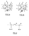
- FIGS 1a and 1b show the same position switch 1, one in the rest position and the other in the working position, which will be used to explain the operation of the anomaly detector according to the present invention.
- This position switch 1 comprises a body 2 having a cavity 3, two pairs of fixed contacts 4,4 'and 5,5' arranged one at the top of the cavity 3 and the other at the bottom, and two movable contacts 6 and 7 secured to a push button 8 associated with a spring 9 working in compression.
- the movable contact 6 engages the fixed contacts 4 and 4 ', while the movable contact 7 does not touch the fixed contacts 5 and 5'.
- the push button 8 is moved downward, the movable contact 6 first separates from the fixed contacts 4 and 4 '. After a period which depends on the speed of movement of the push button 8, the movable contact 7 engages the fixed contacts 5 and 5 '. The release of the push button 8 first causes the contacts 5 and 5 'to open, followed by the contacts 4 and 4' to close.
- the operating anomaly detector 60 makes it possible to develop such an alarm signal; an alarm signal also appears when one or the other contact is not made, that is to say an "all or nothing" anomaly whereas in the first case, it is an anomaly which only partially obstructs the functioning of the position switch and which is in a way an anomaly which makes it possible to carry out a preventive action.
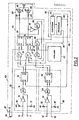
- the anomaly detector 60 (FIG. 2) very schematically comprises two pairs of input terminals 10,11 and 12,13, two input circuits 20 and 30 whose inputs are constituted respectively by said pairs of input terminals 10, 11 and 12, 13, a counting-decoding circuit 35, a clock circuit 40, a fault detection and storage circuit 45 and a display circuit for detected faults 50.
- Each input circuit 20 or 30 includes an OR logic circuit 14 (24 for circuit 30) whose two inputs are connected, one directly to the input terminal 11 (13) and to a resistor 17 (27) and the other to the input terminal 10 (12) and to the resistor 16 (26) via an inverter circuit 15 (25). It also includes a bistable circuit 18 (28), the control input S of which is connected to the output of the OR circuit 14 (24), while the reset input R is connected to a first output 33 of the circuit of counting-decoding 35.
- the fault detection and storage circuit 45 comprises four AND circuits 19, 21, 22 and 46, two bistable circuits 23 and 29, an inverter circuit 31, an OR circuit 17 and a resistor 32.
- the two inputs of the AND circuit 19 are connected, one to the output Q of the bistable circuit 18 and the other to the output Q of the bistable circuit 28; the output of the AND circuit 19 is connected to the control input S of the bistable circuit 23.
- the output Q of the bistable circuit 23 is connected, on the one hand, to the display circuit 50 and, on the other hand, to one of the two inputs of the AND circuit 22.
- the two inputs of the AND circuit 21 are connected one to the output Q of the bistable circuit 18 and the other to a second output 34 of the counting-decoding circuit 35.
- the output of the AND circuit 21 is connected to the input of control S of the bistable circuit 29, the output Q of which is connected, on the one hand, to the display circuit 50 and, on the other hand, to the second input of the AND circuit 22 via the inverter circuit 31.
- the AND circuit 46 receives on one input pulses supplied by the clock circuit 40 and on the other input the output signal of an OR circuit 47.
- One of the two inputs of the OR circuit 47 is connected to the output Q of the bistable circuit 28 while the other input is connected to the output of the AND circuit 22.
- a reset command for example a push button 36 disposed on the housing of the anomaly detector 60, is connected to each input R of the two bistable circuits 23 and 29, to their resistor 32 and to a terminal 37 at a potential. positive.
- the display circuit 50 comprises, for example, two light emitting diodes 38 and 39 connected on one side to a negative potential terminal 41 and, on the other side, to the output Q of the bistable circuit 23 for the diode 38 via a resistor 42 and at the output Q of the bistable circuit 29 for the diode 39 via a resistor 43.
- the counting-decoding circuit 35 comprises a counter 44 which receives the pulses from the clock circuit 40 via an AND circuit 48.
- the counting-decoding circuit 35 also includes a decoder 48, the inputs of which are connected to the counter 44 and of which two decoded outputs 33 and 34 are used.
- the clock circuit 40 is of the conventional type and will not be described in more detail.
- the operation of the anomaly detector in FIG. 2 is then as follows, in the case where the electrical device to be monitored is the position switch in FIG. 1.
- the anomaly detector does not carry out monitoring when the position switch, and more generally, the electrical device to be monitored, is in the rest state.
- connections to be made between the electrical device to be monitored and the input terminals 10, 11, 12 and 13 must be so that, in the idle state of the electrical device, the detector 60 remains inert.
- These connections therefore depend on the electrical levels present in the electrical device to be monitored. They also depend on the event which will occur first when the electrical device goes into working state. Indeed, as the operation will show, it is important that the counter 44 is started as soon as the electrical device is actuated. However, this start-up is controlled by the bistable circuit 28 connected to the pair of input terminals 12 and 13. As a result, one or other of the terminals 12, 13 must be connected in contact with the electrical device which changes state first.
- the first event when the push button 8 is pressed, is the opening of the circuit between the contacts 4,4 'and 6, it is therefore the contact 4 which must be connected to one of terminals 12 or 13; as the contact 4 is at a positive level, it will have no effect in the rest state on the bistable circuit 28 if it is connected to the terminal 12.
- the second event when the push button 8 is actuated, is closing the circuit between the contacts 5.5 'and 7, so that the contact 5 must be connected to one of the input terminals 10 or 11, and more precisely to terminal 11, because at rest, the contact 5 is at a floating potential, but terminal 11 is biased to ground by resistor 17.
- the decoder circuit 48 provides on output 33 a reset signal to the counter 44 and to the bistable circuits 18 and 28, which has the effect of closing the AND circuits 19 , 21 and 46 but does not modify the state of the bistable circuit 29 which continues to indicate a fault.
- this reset signal on output 33 appears at each cycle of the anomaly detector so that the latter is ready to monitor the operation of the switch during a subsequent actuation of the push button.
- the AND circuit 22 provides a signal which opens the AND circuit 46 so that the counter 44 receives the pulses from the clock circuit 40.
- the two diodes 38 and 39 are therefore lit, which indicates that the operation of the position switch is too long.
- one or both of the diodes 38 or 39 light up and can only go out if an operator actuates the reset button 36 which is connected to the input of the reset to zero of the bistable circuits 23 and 29.
- the (or the diodes) will light up again.
- the anomaly detector according to the invention has been described, in particular as regards its operation, in relation to a position switch acting as an electrical device to be monitored.
- this anomaly detector can be used to monitor other electrical, electronic, electromechanical or even electrotechnical devices.
- the device can be an electrical switch 53 (FIG. 3) between two points 51 and 52 which is for example open in the rest position. In this case, point 51 is connected to input terminal 12 and point 52 to input terminal 11. Through these connections, the anomaly detector is inert because the bistable circuits 18 and 28 remain at state 0. If the switch 53 is closed, there is first a fluctuation in the potential level at 51, which causes state 1 of the bistable circuit 28 and therefore the starting of the counter 44. Then , point 52 goes to a positive level, which causes state 1 of the bistable circuit 18.
- bistable circuit 29 changes state when the output 34 is activated and the diode 39 lights up to indicate an alarm.
- the invention has been described in a monitoring function, that is to say by simply providing indications on the existence of an anomaly; it is clear that the information collected can then be used in an active manner, that is to say by causing an action on the electrical device itself or by putting into service a spare electrical device which was previously pending.
- the detector can also be used to give information on correct operation by means of an appropriate display as long as an anomaly is not detected. Instead of using light-emitting diodes to signal faults, one or more audible alarms can also be used.
Landscapes
- Physics & Mathematics (AREA)
- General Physics & Mathematics (AREA)
- Transmission And Conversion Of Sensor Element Output (AREA)
- Electronic Switches (AREA)
Applications Claiming Priority (2)
| Application Number | Priority Date | Filing Date | Title |
|---|---|---|---|
| FR8702641A FR2611915B1 (fr) | 1987-02-27 | 1987-02-27 | Detecteur d'anomalie de fonctionnement d'un dispositif electrique, electrotechnique ou electronique |
| FR8702641 | 1987-02-27 |
Publications (1)
| Publication Number | Publication Date |
|---|---|
| EP0283346A1 true EP0283346A1 (de) | 1988-09-21 |
Family
ID=9348407
Family Applications (1)
| Application Number | Title | Priority Date | Filing Date |
|---|---|---|---|
| EP88400378A Withdrawn EP0283346A1 (de) | 1987-02-27 | 1988-02-19 | Anzeigegerät für einen anormalen Betriebszustand eines elektronischen, elektromechanischen oder elektrischen Gerätes |
Country Status (4)
| Country | Link |
|---|---|
| EP (1) | EP0283346A1 (de) |
| FR (1) | FR2611915B1 (de) |
| NO (1) | NO880858L (de) |
| OA (1) | OA08812A (de) |
Cited By (1)
| Publication number | Priority date | Publication date | Assignee | Title |
|---|---|---|---|---|
| RU2241494C2 (ru) * | 1999-02-09 | 2004-12-10 | Вирсоль | Материал для наложения швов на раны на базе метилиденмалоната |
Citations (5)
| Publication number | Priority date | Publication date | Assignee | Title |
|---|---|---|---|---|
| US3771048A (en) * | 1972-04-13 | 1973-11-06 | Western Electric Co | Sealed contact switch testing apparatus utilizing helmholtz coils |
| US3988664A (en) * | 1975-02-18 | 1976-10-26 | Burroughs Corporation | System for predicting or detecting a fault in a solenoid utilization system |
| GB2079466A (en) * | 1980-06-26 | 1982-01-20 | United Technologies Corp | Sensor fault detection by activity monitoring |
| US4319193A (en) * | 1980-05-14 | 1982-03-09 | Northern Telecom Limited | Testing of relays and similar devices |
| EP0080857A1 (de) * | 1981-11-26 | 1983-06-08 | British Nuclear Fuels PLC | Prüfschaltung für Netzschutzschalter |
Family Cites Families (3)
| Publication number | Priority date | Publication date | Assignee | Title |
|---|---|---|---|---|
| JPS57119261A (en) * | 1981-01-16 | 1982-07-24 | Canon Inc | Measuring device for dynamic characteristic of switch |
| JPS5834373A (ja) * | 1981-08-26 | 1983-02-28 | Toshiba Corp | リミツトスイツチの試験装置 |
| US4686478A (en) * | 1985-06-05 | 1987-08-11 | Westinghouse Electric Corp. | Testing device for detecting contact chatter in electrical components with movable contacts, such as relays |
-
1987
- 1987-02-27 FR FR8702641A patent/FR2611915B1/fr not_active Expired
-
1988
- 1988-02-19 EP EP88400378A patent/EP0283346A1/de not_active Withdrawn
- 1988-02-26 OA OA59292A patent/OA08812A/xx unknown
- 1988-02-26 NO NO880858A patent/NO880858L/no unknown
Patent Citations (5)
| Publication number | Priority date | Publication date | Assignee | Title |
|---|---|---|---|---|
| US3771048A (en) * | 1972-04-13 | 1973-11-06 | Western Electric Co | Sealed contact switch testing apparatus utilizing helmholtz coils |
| US3988664A (en) * | 1975-02-18 | 1976-10-26 | Burroughs Corporation | System for predicting or detecting a fault in a solenoid utilization system |
| US4319193A (en) * | 1980-05-14 | 1982-03-09 | Northern Telecom Limited | Testing of relays and similar devices |
| GB2079466A (en) * | 1980-06-26 | 1982-01-20 | United Technologies Corp | Sensor fault detection by activity monitoring |
| EP0080857A1 (de) * | 1981-11-26 | 1983-06-08 | British Nuclear Fuels PLC | Prüfschaltung für Netzschutzschalter |
Non-Patent Citations (2)
| Title |
|---|
| IBM TECHNICAL DISCLOSURE BULLETIN, vol. 25, no. 7A, décembre 1983, pages 3211-3212, New York, US; R.M. COVEY et al.: "Relay tester for a microminiature relay" * |
| IBM TECHNICAL DISCLOSURE BULLETIN, vol. 9, no. 4, septembre 1966, page 367, New York, US; M.F. HEILWEIL et al.: "Testing electromagnetic switching devices" * |
Cited By (1)
| Publication number | Priority date | Publication date | Assignee | Title |
|---|---|---|---|---|
| RU2241494C2 (ru) * | 1999-02-09 | 2004-12-10 | Вирсоль | Материал для наложения швов на раны на базе метилиденмалоната |
Also Published As
| Publication number | Publication date |
|---|---|
| FR2611915B1 (fr) | 1989-07-07 |
| FR2611915A1 (fr) | 1988-09-09 |
| OA08812A (fr) | 1989-03-31 |
| NO880858D0 (no) | 1988-02-26 |
| NO880858L (no) | 1988-08-29 |
Similar Documents
| Publication | Publication Date | Title |
|---|---|---|
| EP0537084B1 (de) | Schutzschalter mit selektiver Verriegelung | |
| EP0048192B1 (de) | Anordnung zum automatischen Prüfen einer Vielzahl von Anzeigelampen | |
| CH669057A5 (fr) | Installation de surveillance et d'alarme. | |
| FR2555331A1 (fr) | Circuit comprenant un micro-ordinateur destine notamment au reglage du siege d'un vehicule automobile | |
| FR2541008A1 (fr) | Systeme pour controler le fonctionnement des transducteurs de sortie d'une unite centrale de commande et de controle pour des machines et/ou des dispositifs utilisables dans des lignes de production et/ou des lignes d'emballage de produits | |
| EP0112740A1 (de) | Elektronische Treiberschaltung für Geräte mit mehreren Betriebsarten und ausgerüstet mit einem Elektromagnettriebwerk | |
| EP0283346A1 (de) | Anzeigegerät für einen anormalen Betriebszustand eines elektronischen, elektromechanischen oder elektrischen Gerätes | |
| FR2515867A1 (fr) | Dispositif a contacteurs de commande de circuits electriques | |
| EP0536058B2 (de) | Elektronischer Auslöser mit lokale den detektierten Fehler anzeigende Mittel | |
| FR2540685A1 (fr) | Interface pour relier un systeme informatique a un dispositif actionneur | |
| WO2000063932A1 (fr) | Systeme de diagnostic de contact electrique a deplacement mecanique | |
| EP0074674B1 (de) | Logische Sicherheitsschaltungen, insbesondere verwendbar in Eisenbahnsignalanlagen | |
| EP0874437B1 (de) | Schaltung zum Start einer Maschine oder dergleichen und Verfahren zur Steuerung eines Starts einer Maschine | |
| FR2548413A1 (fr) | Procedes et dispositifs pour eviter des fraudes sur un taxi equipe d'un repetiteur lumineux | |
| WO1997040578A1 (fr) | Relais statique avec detection d'etat | |
| EP0202146B1 (de) | Vorrichtung zum Schutz einer kodierten elektromechanischen Bedienungsanlage vor Beschädigungen durch Stösse oder bei Entwendungsversuchen | |
| EP0324524B1 (de) | Lage-Detektor | |
| FR2717004A1 (fr) | Circuit pour dispositif de signalisation équipant des disjoncteurs de protection. | |
| FR2568065A1 (fr) | Dispositif de test d'autonomie pour bloc d'eclairage de securite | |
| EP0433514A1 (de) | Prüfbare Eingangs-Ausgangsanordnung für transformatorisch entkoppelte Last | |
| FR2495359A1 (fr) | Dispositif d'alarme a securite positive | |
| EP4503083A1 (de) | Elektrische schutzvorrichtung, die zur automatischen bestimmung einer ursache einer öffnung einer elektrischen schaltung konfiguriert ist, und verfahren dafür | |
| EP3835645A1 (de) | Sicherheitsdetektor und sicherheitsdetektionssystem, das diesen sicherheitsdetektor umfasst | |
| FR2616256A1 (fr) | Procede de detection de l'evolution dans le temps des proprietes electriques d'une ligne au moins bifilaire, moyens pour la mise en oeuvre de ce procede et installations comprenant au moins une ligne conductrice equipee de ces moyens | |
| CH507779A (fr) | Dispositif pour indiquer la présence d'un organe mobile dans une zone prédéterminée de sa trajectoire |
Legal Events
| Date | Code | Title | Description |
|---|---|---|---|
| PUAI | Public reference made under article 153(3) epc to a published international application that has entered the european phase |
Free format text: ORIGINAL CODE: 0009012 |
|
| AK | Designated contracting states |
Kind code of ref document: A1 Designated state(s): AT BE CH DE ES GB GR IT LI LU NL SE |
|
| STAA | Information on the status of an ep patent application or granted ep patent |
Free format text: STATUS: THE APPLICATION IS DEEMED TO BE WITHDRAWN |
|
| 18D | Application deemed to be withdrawn |
Effective date: 19890322 |