EP0283355A1 - Elastische Montage einer Schiene auf ihren Träger ohne Schraubmittel und Durchführungsverfahren - Google Patents
Elastische Montage einer Schiene auf ihren Träger ohne Schraubmittel und Durchführungsverfahren Download PDFInfo
- Publication number
- EP0283355A1 EP0283355A1 EP88400412A EP88400412A EP0283355A1 EP 0283355 A1 EP0283355 A1 EP 0283355A1 EP 88400412 A EP88400412 A EP 88400412A EP 88400412 A EP88400412 A EP 88400412A EP 0283355 A1 EP0283355 A1 EP 0283355A1
- Authority
- EP
- European Patent Office
- Prior art keywords
- rail
- blade
- support
- assembly according
- insert
- Prior art date
- Legal status (The legal status is an assumption and is not a legal conclusion. Google has not performed a legal analysis and makes no representation as to the accuracy of the status listed.)
- Granted
Links
- 238000000034 method Methods 0.000 title claims abstract description 5
- 238000006243 chemical reaction Methods 0.000 claims description 4
- 230000000694 effects Effects 0.000 claims description 4
- 238000000465 moulding Methods 0.000 claims description 4
- 239000002131 composite material Substances 0.000 claims description 2
- 238000003780 insertion Methods 0.000 claims 1
- 230000037431 insertion Effects 0.000 claims 1
- 239000011229 interlayer Substances 0.000 claims 1
- 238000004519 manufacturing process Methods 0.000 description 3
- 238000009434 installation Methods 0.000 description 2
- 239000011810 insulating material Substances 0.000 description 2
- 239000004952 Polyamide Substances 0.000 description 1
- 229910000746 Structural steel Inorganic materials 0.000 description 1
- 230000000712 assembly Effects 0.000 description 1
- 238000000429 assembly Methods 0.000 description 1
- 230000005540 biological transmission Effects 0.000 description 1
- 230000003247 decreasing effect Effects 0.000 description 1
- 238000006073 displacement reaction Methods 0.000 description 1
- 238000010292 electrical insulation Methods 0.000 description 1
- 238000005242 forging Methods 0.000 description 1
- 238000007373 indentation Methods 0.000 description 1
- 230000001939 inductive effect Effects 0.000 description 1
- 238000009413 insulation Methods 0.000 description 1
- 239000012212 insulator Substances 0.000 description 1
- 238000002955 isolation Methods 0.000 description 1
- 239000002184 metal Substances 0.000 description 1
- 229910052751 metal Inorganic materials 0.000 description 1
- 229920002647 polyamide Polymers 0.000 description 1
- 230000037452 priming Effects 0.000 description 1
Images


Classifications
-
- E—FIXED CONSTRUCTIONS
- E01—CONSTRUCTION OF ROADS, RAILWAYS, OR BRIDGES
- E01B—PERMANENT WAY; PERMANENT-WAY TOOLS; MACHINES FOR MAKING RAILWAYS OF ALL KINDS
- E01B9/00—Fastening rails on sleepers, or the like
- E01B9/02—Fastening rails, tie-plates, or chairs directly on sleepers or foundations; Means therefor
- E01B9/28—Fastening on wooden or concrete sleepers or on masonry with clamp members
- E01B9/30—Fastening on wooden or concrete sleepers or on masonry with clamp members by resilient steel clips
- E01B9/306—Fastening on wooden or concrete sleepers or on masonry with clamp members by resilient steel clips the clip being a shaped plate
Definitions
- the present invention relates to an elastic assembly of a rail on a support, not involving screwing means for tightening the rail on the support.
- the elastic fasteners of rails constituted by leaf springs, for example, described in French patent N ° 2 411 920 and its certificate of addition N * 2 426 770, in which the springs are bent parallel or perpendicular to the axis of the rail, ensure the fastening of the rail on its support by tensioning the blade between a support on the shoe of the rail and a support on the support.
- This tensioning is traditionally carried out by means of a nut screwed onto a bolt passing through the blade via a hole, and sealed or anchored by any means in the support.
- a washer is placed between the nut and the blade to distribute the pressures on the latter.
- screwed fasteners present the risk of over-tightening, insufficient tightening or accidental loosening.
- the device according to the invention overcomes these drawbacks.
- the subject of the invention is an elastic assembly of a rail on a support, of the type comprising a spring means and capable of exerting pressure on the shoe of the rail by means of an intermediate element and cooperating with a retaining element anchored in the support, characterized in that the spring means consists of a blade bearing on the intermediate element and on which the retaining element is supported vertically so as to allow the introduction of the intermediate element and the blade under the holding element in a direction parallel to the rail.
- the holding element has a valet shape and is anchored in the support in the vicinity of the rear part of the blade.
- the retaining element comprises in its front part an element applicable to the blade, by its part or lower surface, which comprises a boss or circular shapes forming a boss cooperating with a hollow imprint of corresponding shape, the blade.
- the intermediate element and the leaf spring form a unitary assembly by virtue of a hollow housing of trapezoidal shape provided on the intermediate element and with two snaps.
- the intermediate element and the leaf spring can constitute a unitary part obtained by molding the intermediate element in which the leaf spring is incorporated.
- the holding element consists of an insert comprising in its middle part an element intended to receive a stop for lateral positioning of the rail.
- the intermediate element constitutes an insulating case in which is threaded at least partially the leaf spring.
- the leaf spring has a horizontal part threaded into the case mentioned above and extended by a curved S-shaped part cooperating with the holding element.
- the aforementioned leaf spring forms at its free end a circular part comprising two inclined surfaces directed downwards and cooperating with corresponding surfaces of the aforementioned element of the holding element to put the blade in tension under the effect of a thrust exerted on the blade, parallel to the rail.
- the element of the middle part of the insert has two lateral parts, the inner faces of which form a dovetail and cooperate with corresponding surfaces of the stop to prevent vertical movements of this stop.
- the retaining element comprises a rebate serving as a reaction support for the rear part or heel of the leaf spring and the support side of which is located at a constant distance from the underside of the upper element of the holding element.
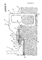
- the device according to the invention comprises a rail 1 supported by a cross member or support 2 by means of an elastic sole 3 disposed between them.
- the lateral position of the rail is ensured by an intermediate element 4 which abuts on the one hand, against the pad 5 of the rail 1 , and on the other hand against a shoulder 6 of the support 2.
- This intermediate element 4 comprises two wings 7 and 8 respectively partially enveloping the shoe 5 of the rail 1 and the shoulder 6 of the support 2.
- a spring leaf 9 applies a vertical force directed from top to bottom on the intermediate element 4 and thus builds on it.
- the blade 9 is held on the intermediate element 4 to form therewith a unitary assembly, on the one hand in a horizontal position, thanks to a recess of trapezoidal surface formed by rims 4a of the intermediate element 4, and on the other hand in a vertical position by two snaps 4b.
- the snaps 4b can be produced by ultrasonic forging of two bosses after positioning of the blade 9 on the intermediate element 4.
- the intermediate element can be made of insulating material, such as polyamide or the like.
- the blade-insert assembly 9, 4 to constitute a unitary piece can be produced by the molding of the intermediate element 4 with the leaf spring 9 taken as an armature, the leaf spring 9 then being incorporated during the molding operation with the intermediate element.
- the blade 9 is held by one or more flanges 4c bent horizontally on the blade 9 towards the rear part 9a thereof.
- the insert 10, anchored in the support 2 in the vicinity of the rear part 9a of the blade 9, consists of two vertical sails 11, visible in FIG. 2, perpendicular to the rail, and which have two recesses 12 and 13 located at on either side of the upper face 14 of the support 2.
- the lower recess 13, anchored and sealed inside the support 2, is partly active in the pull-out resistance of the insert 10.
- the upper recess 12 allows the passage of a gripping means intended on the one hand, for the handling of the support 2 during its manufacture, and on the other hand for the exact positioning of the support 2 relative to the rail 1.
- the two sails 11 are made integral with each other by through a rebate 15 and a circular element 17.
- the rebate 15, parallel to the rail, constitutes a dihedral whose horizontal face 16 is in the same plane as the upper face 14 of the support 2 and serves as a reaction support for the rear part or heel 9a of the blade 9.
- the circular element 17, located at the front of the valet on the side closest to the rail, has a horizontal lower face 18 coming into contact with the blade 9 and maintaining the latter in the working position, the valet thus taking vertically support on the blade 9.
- a boss 19 directed towards the support and located in the center of the lower face 18 of the circular element 17 cooperates with a recess 20 of the blade 9, of corresponding shape, to prevent longitudinal and transverse displacements of this blade.
- this distance is constant and makes it possible to obtain a very great homogeneity of the tightening of the rail on the support, by the elastic assemblies arranged along, and on either side of each rail.
- the horizontal faces 22 and 24 of the T-shaped elements 21 are located in the same plane as the upper face 14 of the support 2.
- two flanges 25 have their upper horizontal face 26 in the same plane as the upper face 14 of the support 2.
- the horizontal surfaces 16, 22, 24 and 26 cooperate with the vertical surfaces 27 of the rear of the webs 11 to ensure the positioning of the insert 10 in the mold intended for the manufacture of the support 2.
- the implementation of the elastic assembly according to the invention is as follows:
- the blade-insert assembly 9, 4 is positioned on the support 2 and on the rail 1 next to the holding element or valet 10, as shown in FIGS. 1 and 2 by the dashed or dashed lines 30 , the blade 9 then being in the rest position.
- a vertical movement is then applied from the bottom upwards to firmly hold the support 2 against the underside of the shoe 5 of the rail 1.
- a vertical movement directed from top to bottom is applied, inducing a vertical pressure on the blade to bring the latter into the working position and to preposition the blade-insert assembly 9, 4 in this same position, then apply a longitudinal movement parallel to the rail to the blade-insert assembly 9, 4 in order to introduce it into its final position under the holding element in the form of a valet or insert 10.
- the elastic assembly comprises a holding element or insert 31 in the form of a valet made up of a single vertical veil 32 of appropriate sections, having good resistance to spillage under the effect of the vertical forces generated by the blade 33 in the working position.
- the vertical veil 32 of the insert 31 is provided with an upper recess 31a and with a lower recess 31b, the latter being sealed and anchored in the support or cross 2, while the first allows, among other things, the passage of a gripping means.
- the upper front part 34a of the insert 31, closest to the rail 1, is constituted by an element 35 whose cross section, perpendicular to the rail, comprises at its lower part 35a directed towards the shoe 5 of the rail 1, a shape circular 35b.
- the longitudinal section of the element 35 parallel to the rail a, at the lower part 35a, a circular part 35c extended on either side by two sloping surfaces 36 and 37, inclined upwards from the element 35, the circular shapes 35b and 35c forming a boss.
- this element 35 in its part closest to the rail, is constituted by a vertical flat surface 38 connected to a bias portion 39 of the valet 31 and located a few millimeters outside, relative to the rail 1, of the plane passing through a vertical face 5a of the pad 5 of the rail 1, forming the edge thereof.
- the holding element or insert 31 is constituted by an element 40 whose cross section, perpendicular to the rail, has a form of angle iron whose horizontal internal face 41 is located in the same plane as the upper face 2a of the support 2 intended to receive the elastic sole 3 and the rail 1.
- the length, parallel to the rail, of this element 40 is such that it allows an effective stop to the lateral forces exerted by the shoe 5 of the rail 1 and transmitted by a positioning stop 42.
- the lateral parts 43, perpendicular to the rail 1, of this element 40 have a length d, visible in FIG. 3, less than the width of the horizontal internal face 41 of the element 40 and constituting by their internal faces 40a, 40b, a dovetail 40c.
- the lateral stop of the rail 1 is ensured by the positioning stop 42, the lateral surfaces 42a and 42b of which correspond to those formed by the internal faces 40a, 40b of the element 40 disposed at the middle part 34b of the insert 31.
- This stop 42 is glued into the insert 31 during the manufacture of the support 2 and ensures the positioning of the rail 1 on the support 2 during the setting up.
- the insulation between the rail 1 and the leaf spring 33 is produced by an intermediate element 43 which constitutes an insulating case in which the leaf spring 33 is at least partially threaded.
- the leaf spring and the intermediate element 43 form a unitary assembly.
- the stop 42 After mounting the rail 1 on its support 2, the stop 42 is immobilized, in horizontal translation by the inner faces 40a, 40b of the element 40 of the middle part 34b of the insert 31 and by the vertical face 5a of the shoe 5 of the rail 1 against which it abuts, and in vertical translation by the dovetail 40c formed by the interior surfaces 40a, 40b of the lateral parts 43 of the element 40.
- the leaf spring 33 produced for example from a laminated plate, comprises a horizontal part 44 threaded into the insulating case 43, bearing via a boss 43a of the case insulator 43 on the one hand, on a horizontal rear surface 40d forming the rebate of the median element 40 of the insert 31, and on the other hand on the shoe 5 of the rail 1.
- This horizontal part 44 is extended on the side of the 'support on the shoe 5 of the rail 1 by a circular part 45 directed upwards and constituting approximately three quarters of a circle, and extended by another part 46 comprising a circular shape corresponding to the lower part 35b of the element 35 of the upper part 34a of the insert 31 and constituting with the preceding part 45 an S .
- the last part 46 disposed at the free end of the leaf spring 33 has respectively in its cross section and in its longitudinal section circular shapes 46a and 46b forming an indentation, corresponding to the circular shapes or boss 35b, 35c of l element 35 of the upper part 34a of the insert 31, the longitudinal circular part 46b being extended on either side by two surfaces 47, 48, sloping, inclined downward and of the same inclination as the respective respective surfaces 36 and 37 of element 35 of the insert.
- the blade 33 is put in place under the effect of a force F exerted parallel to the rail 1, the sloping surfaces 47 and 48 of the blade 33 and the sloping surfaces 37 and 36 of the element 35 cooperating to bring the leaf-spring 33 in the working position, as a function of the prior position of the leaf-insert assembly with respect to the insert 31.
- the working position, or the application of a clamping force S, is maintained by the longitudinal circular 35c and transverse 35b parts of the element 35 of the insert 31, forming a boss, and cooperating with the corresponding shaped parts. 46b and 46a forming an imprint of the leaf spring 33.
- such a device allows the application of a clamping force S in a stress zone. zero, and on the other hand obtaining, for the same effort, a deflection under load of the blade more or less significant by increasing or decreasing the length of the median circular part 45 of the blade without variation in stress, the distances between points of application of the forces being constant, as for the first embodiment.
- a deflection loss of 1 mm results in a pressure drop of one tenth of the initial value of the load while for a conventional assembly device the deflection of the blade obtained at right tightening by the application of a tightening force is generally limited by the value of the stresses, the tightening means being generally located in the vicinity of the zone of maximum stress developed in this blade by this tightening means.
- known deflections generally obtained of the order of 4 mm require a precise vertical positioning of different elements between them, a loss of deflection of 1 mm therefore resulting in a pressure drop of a quarter of the value initial charge.
- this second embodiment of the invention allows, thanks to the shape of the spring element 33 and the position relative to the rail of the element 35 of the upper part 34a of the insert, to remedy to these disadvantages.
- the insert 10, 31 and / or the spring leaf 9, 33 can be made of an insulating composite material, which makes it possible to eliminate the insulating case 43 forming an insert and the insert 4.
- the functions fulfilled by the intermediate element described in the first embodiment are separated by means of the element 40 of the middle part 34b of the insert 31, at namely on the one hand, the electrical insulation between the leaf spring and the rail, and on the other hand the stop function for the transmission of the lateral forces induced by the shoe of the rail.
Landscapes
- Engineering & Computer Science (AREA)
- Mechanical Engineering (AREA)
- Architecture (AREA)
- Civil Engineering (AREA)
- Structural Engineering (AREA)
- Footwear And Its Accessory, Manufacturing Method And Apparatuses (AREA)
- Railway Tracks (AREA)
- Connection Of Plates (AREA)
- Springs (AREA)
- Clamps And Clips (AREA)
- Mounting Components In General For Electric Apparatus (AREA)
Priority Applications (1)
| Application Number | Priority Date | Filing Date | Title |
|---|---|---|---|
| AT88400412T ATE63585T1 (de) | 1987-02-24 | 1988-02-23 | Elastische montage einer schiene auf ihren traeger ohne schraubmittel und durchfuehrungsverfahren. |
Applications Claiming Priority (4)
| Application Number | Priority Date | Filing Date | Title |
|---|---|---|---|
| FR8702368A FR2611765B1 (fr) | 1987-02-24 | 1987-02-24 | Assemblage elastique d'un rail sur son support sans moyen de vissage et son procede de mise en oeuvre |
| FR8702368 | 1987-02-24 | ||
| FR878714029A FR2621620B2 (fr) | 1987-02-24 | 1987-10-12 | Assemblage elastique d'un rail sur son support sans moyen de vissage et son procede de mise en oeuvre |
| FR8714029 | 1987-10-12 |
Publications (2)
| Publication Number | Publication Date |
|---|---|
| EP0283355A1 true EP0283355A1 (de) | 1988-09-21 |
| EP0283355B1 EP0283355B1 (de) | 1991-05-15 |
Family
ID=26225798
Family Applications (1)
| Application Number | Title | Priority Date | Filing Date |
|---|---|---|---|
| EP88400412A Expired - Lifetime EP0283355B1 (de) | 1987-02-24 | 1988-02-23 | Elastische Montage einer Schiene auf ihren Träger ohne Schraubmittel und Durchführungsverfahren |
Country Status (14)
| Country | Link |
|---|---|
| EP (1) | EP0283355B1 (de) |
| JP (1) | JPH01502920A (de) |
| KR (1) | KR890700719A (de) |
| AU (1) | AU1429188A (de) |
| BR (1) | BR8805638A (de) |
| DE (1) | DE3862786D1 (de) |
| ES (1) | ES2022995B3 (de) |
| FR (1) | FR2621620B2 (de) |
| GR (1) | GR3002470T3 (de) |
| MA (1) | MA21188A1 (de) |
| MX (1) | MX167891B (de) |
| PT (1) | PT86825B (de) |
| TN (1) | TNSN88017A1 (de) |
| WO (1) | WO1988006660A1 (de) |
Citations (6)
| Publication number | Priority date | Publication date | Assignee | Title |
|---|---|---|---|---|
| DE528046C (de) * | 1929-08-31 | 1931-06-25 | August Hahmann | Gelenklager fuer Eisenbahnschienen |
| US2535337A (en) * | 1947-06-05 | 1950-12-26 | Carnegie Illinois Steel Corp | Rail fastening device |
| FR2096274A5 (de) * | 1970-06-12 | 1972-02-11 | Lesjofors Ab | |
| US3883072A (en) * | 1974-04-05 | 1975-05-13 | Portec Inc | Rail anchor |
| GB1434560A (en) * | 1972-08-16 | 1976-05-05 | Wiggill R G | Rail fastening method and assembly |
| GB1496390A (en) * | 1976-06-21 | 1977-12-30 | Pandrol Ltd | Device for electrically insulating a railway rail from parts securing it |
Family Cites Families (1)
| Publication number | Priority date | Publication date | Assignee | Title |
|---|---|---|---|---|
| JPS55108503A (en) * | 1979-02-13 | 1980-08-20 | Tokou Shigetarou | Elastic clamp apparatus for rail |
-
1987
- 1987-10-12 FR FR878714029A patent/FR2621620B2/fr not_active Expired - Lifetime
-
1988
- 1988-02-19 MA MA21426A patent/MA21188A1/fr unknown
- 1988-02-23 ES ES88400412T patent/ES2022995B3/es not_active Expired - Lifetime
- 1988-02-23 AU AU14291/88A patent/AU1429188A/en not_active Abandoned
- 1988-02-23 TN TNTNSN88017A patent/TNSN88017A1/fr unknown
- 1988-02-23 BR BR888805638A patent/BR8805638A/pt not_active IP Right Cessation
- 1988-02-23 DE DE8888400412T patent/DE3862786D1/de not_active Expired - Fee Related
- 1988-02-23 WO PCT/FR1988/000102 patent/WO1988006660A1/fr not_active Ceased
- 1988-02-23 JP JP63502218A patent/JPH01502920A/ja active Pending
- 1988-02-23 EP EP88400412A patent/EP0283355B1/de not_active Expired - Lifetime
- 1988-02-24 MX MX010534A patent/MX167891B/es unknown
- 1988-02-24 PT PT86825A patent/PT86825B/pt not_active IP Right Cessation
- 1988-10-24 KR KR1019880701338A patent/KR890700719A/ko not_active Abandoned
-
1991
- 1991-08-14 GR GR91401206T patent/GR3002470T3/el unknown
Patent Citations (6)
| Publication number | Priority date | Publication date | Assignee | Title |
|---|---|---|---|---|
| DE528046C (de) * | 1929-08-31 | 1931-06-25 | August Hahmann | Gelenklager fuer Eisenbahnschienen |
| US2535337A (en) * | 1947-06-05 | 1950-12-26 | Carnegie Illinois Steel Corp | Rail fastening device |
| FR2096274A5 (de) * | 1970-06-12 | 1972-02-11 | Lesjofors Ab | |
| GB1434560A (en) * | 1972-08-16 | 1976-05-05 | Wiggill R G | Rail fastening method and assembly |
| US3883072A (en) * | 1974-04-05 | 1975-05-13 | Portec Inc | Rail anchor |
| GB1496390A (en) * | 1976-06-21 | 1977-12-30 | Pandrol Ltd | Device for electrically insulating a railway rail from parts securing it |
Non-Patent Citations (1)
| Title |
|---|
| MODERN PLASTICS, vol. 41, no. 5, janvier 1964, page 118-132, Lausanne, CH: "Plastics in Japan: Progress and innovation" * |
Also Published As
| Publication number | Publication date |
|---|---|
| PT86825A (pt) | 1989-02-28 |
| ES2022995B3 (es) | 1991-12-16 |
| FR2621620B2 (fr) | 1991-12-13 |
| MX167891B (es) | 1993-04-21 |
| BR8805638A (pt) | 1989-10-17 |
| JPH01502920A (ja) | 1989-10-05 |
| TNSN88017A1 (fr) | 1990-07-10 |
| DE3862786D1 (de) | 1991-06-20 |
| PT86825B (pt) | 1993-08-31 |
| WO1988006660A1 (fr) | 1988-09-07 |
| FR2621620A2 (fr) | 1989-04-14 |
| AU1429188A (en) | 1988-09-26 |
| GR3002470T3 (en) | 1992-12-30 |
| KR890700719A (ko) | 1989-04-27 |
| EP0283355B1 (de) | 1991-05-15 |
| MA21188A1 (fr) | 1988-10-01 |
Similar Documents
| Publication | Publication Date | Title |
|---|---|---|
| EP0076765B1 (de) | Festschraubvorrichtung zum Fixieren auf einem Profil und Zusammensetzung eines Profils mit einer derartigen Vorrichtung | |
| EP0823268B1 (de) | Schuhbindungsvorrichtung für ein Gleitbrett | |
| EP1564141B1 (de) | Flugzeugsitzschiene und deren Fertigungsverfahren | |
| EP0740720B1 (de) | Vorrichtung zur befestigung einer eisenbahnschiene | |
| EP0319390B1 (de) | Aufhänger für Gerüstelement, insbesondere für Decken mit einem Stahlgerüst | |
| FR2633341A1 (fr) | Dispositif de fixation pour ecrou a barillet | |
| EP0999368B1 (de) | Befestigungsklammer, insbesondere für Handleuchte | |
| EP0283355B1 (de) | Elastische Montage einer Schiene auf ihren Träger ohne Schraubmittel und Durchführungsverfahren | |
| EP0513105B1 (de) | Vorrichtung zur befestigung von eisenbahnschienen auf einem beton- oder metallträger | |
| FR2755025A1 (fr) | Dispositif de liaison entre une planche a usage sportif, notamment une planche a neige, et une fixation de chaussure | |
| EP0373008A1 (de) | Verbindungsstück zur Montage von Profilen | |
| FR2613550A1 (fr) | Dispositif pour fixer plusieurs cables sur un support | |
| FR2611369A3 (fr) | Fixation de rail | |
| FR2671147A1 (fr) | Dispositif d'immobilisation de deux pieces assemblees par pression de l'une sur l'autre, en particulier pour vehicule automobile. | |
| EP0213002A1 (de) | Zusammenbau eines Kupplungsausrücklagers | |
| FR2590222A1 (fr) | Dispositif de fixation et de securite pour pedales de bicyclettes et de vehicules similaires | |
| FR3021683A1 (fr) | Suspente pour l'accrochage d'un rail de fixation d'un element de doublage en combinaison avec un materiau isolant et une membrane d'etancheite | |
| EP1033948A1 (de) | Tibiaimplantat für knieprothese | |
| FR2677084A1 (fr) | Dispositif d'assemblage pour profiles creux. | |
| EP1186837B1 (de) | Vorrichtung zur Wandbefestigung eines Heizkörpers und Verfahren zu dessen Befestigung | |
| FR2562172A1 (fr) | Dispositif pour l'assemblage demontable de deux composants presentant des ouvertures alignees | |
| FR2611765A1 (fr) | Assemblage elastique d'un rail sur son support sans moyen de vissage et son procede de mise en oeuvre | |
| EP0320371A1 (de) | Seitlich einstellbares Scharnierband | |
| EP0985834A1 (de) | Vorrichtung in Form einer Platte oder ähnlichem zum Befestigen mindestens eines Teils auf einem anderen | |
| FR2820380A1 (fr) | Vehicule automobile avec au moins une barre de toit |
Legal Events
| Date | Code | Title | Description |
|---|---|---|---|
| PUAI | Public reference made under article 153(3) epc to a published international application that has entered the european phase |
Free format text: ORIGINAL CODE: 0009012 |
|
| AK | Designated contracting states |
Kind code of ref document: A1 Designated state(s): AT BE CH DE ES GB GR IT LI LU NL SE |
|
| 17P | Request for examination filed |
Effective date: 19881007 |
|
| 17Q | First examination report despatched |
Effective date: 19891207 |
|
| GRAA | (expected) grant |
Free format text: ORIGINAL CODE: 0009210 |
|
| AK | Designated contracting states |
Kind code of ref document: B1 Designated state(s): AT BE CH DE ES GB GR IT LI LU NL SE |
|
| REF | Corresponds to: |
Ref document number: 63585 Country of ref document: AT Date of ref document: 19910615 Kind code of ref document: T |
|
| REF | Corresponds to: |
Ref document number: 3862786 Country of ref document: DE Date of ref document: 19910620 |
|
| ITF | It: translation for a ep patent filed | ||
| GBT | Gb: translation of ep patent filed (gb section 77(6)(a)/1977) | ||
| PLBE | No opposition filed within time limit |
Free format text: ORIGINAL CODE: 0009261 |
|
| STAA | Information on the status of an ep patent application or granted ep patent |
Free format text: STATUS: NO OPPOSITION FILED WITHIN TIME LIMIT |
|
| 26N | No opposition filed | ||
| REG | Reference to a national code |
Ref country code: GR Ref legal event code: FG4A Free format text: 3002470 |
|
| EPTA | Lu: last paid annual fee | ||
| REG | Reference to a national code |
Ref country code: CH Ref legal event code: PUE Owner name: PANDROL LIMITED |
|
| REG | Reference to a national code |
Ref country code: GB Ref legal event code: 732E |
|
| ITPR | It: changes in ownership of a european patent |
Owner name: CESSIONE;PANDROL LIMITED |
|
| REG | Reference to a national code |
Ref country code: ES Ref legal event code: PC2A Owner name: PANDROL LIMITED |
|
| EAL | Se: european patent in force in sweden |
Ref document number: 88400412.8 |
|
| NLS | Nl: assignments of ep-patents |
Owner name: PANDROL LIMITED TE WEYBRIDGE, GROOT-BRITTANNIE. |
|
| PGFP | Annual fee paid to national office [announced via postgrant information from national office to epo] |
Ref country code: GB Payment date: 19960214 Year of fee payment: 9 |
|
| PGFP | Annual fee paid to national office [announced via postgrant information from national office to epo] |
Ref country code: SE Payment date: 19960215 Year of fee payment: 9 |
|
| PGFP | Annual fee paid to national office [announced via postgrant information from national office to epo] |
Ref country code: BE Payment date: 19960412 Year of fee payment: 9 |
|
| PGFP | Annual fee paid to national office [announced via postgrant information from national office to epo] |
Ref country code: GR Payment date: 19961230 Year of fee payment: 10 |
|
| PGFP | Annual fee paid to national office [announced via postgrant information from national office to epo] |
Ref country code: AT Payment date: 19970213 Year of fee payment: 10 |
|
| PG25 | Lapsed in a contracting state [announced via postgrant information from national office to epo] |
Ref country code: GB Effective date: 19970223 |
|
| PG25 | Lapsed in a contracting state [announced via postgrant information from national office to epo] |
Ref country code: SE Effective date: 19970224 |
|
| PGFP | Annual fee paid to national office [announced via postgrant information from national office to epo] |
Ref country code: NL Payment date: 19970227 Year of fee payment: 10 Ref country code: ES Payment date: 19970227 Year of fee payment: 10 |
|
| PG25 | Lapsed in a contracting state [announced via postgrant information from national office to epo] |
Ref country code: BE Effective date: 19970228 |
|
| PGFP | Annual fee paid to national office [announced via postgrant information from national office to epo] |
Ref country code: DE Payment date: 19970228 Year of fee payment: 10 |
|
| PGFP | Annual fee paid to national office [announced via postgrant information from national office to epo] |
Ref country code: CH Payment date: 19970310 Year of fee payment: 10 |
|
| PGFP | Annual fee paid to national office [announced via postgrant information from national office to epo] |
Ref country code: LU Payment date: 19970327 Year of fee payment: 10 |
|
| BERE | Be: lapsed |
Owner name: PANDROL LTD Effective date: 19970228 |
|
| GBPC | Gb: european patent ceased through non-payment of renewal fee |
Effective date: 19970223 |
|
| EUG | Se: european patent has lapsed |
Ref document number: 88400412.8 |
|
| PG25 | Lapsed in a contracting state [announced via postgrant information from national office to epo] |
Ref country code: LU Free format text: LAPSE BECAUSE OF NON-PAYMENT OF DUE FEES Effective date: 19980223 Ref country code: AT Free format text: LAPSE BECAUSE OF NON-PAYMENT OF DUE FEES Effective date: 19980223 |
|
| PG25 | Lapsed in a contracting state [announced via postgrant information from national office to epo] |
Ref country code: ES Free format text: LAPSE BECAUSE OF NON-PAYMENT OF DUE FEES Effective date: 19980224 |
|
| PG25 | Lapsed in a contracting state [announced via postgrant information from national office to epo] |
Ref country code: LI Free format text: LAPSE BECAUSE OF NON-PAYMENT OF DUE FEES Effective date: 19980228 Ref country code: GR Free format text: LAPSE BECAUSE OF NON-PAYMENT OF DUE FEES Effective date: 19980228 Ref country code: CH Free format text: LAPSE BECAUSE OF NON-PAYMENT OF DUE FEES Effective date: 19980228 |
|
| PG25 | Lapsed in a contracting state [announced via postgrant information from national office to epo] |
Ref country code: NL Free format text: LAPSE BECAUSE OF NON-PAYMENT OF DUE FEES Effective date: 19980901 |
|
| REG | Reference to a national code |
Ref country code: CH Ref legal event code: PL |
|
| NLV4 | Nl: lapsed or anulled due to non-payment of the annual fee |
Effective date: 19980901 |
|
| PG25 | Lapsed in a contracting state [announced via postgrant information from national office to epo] |
Ref country code: DE Free format text: LAPSE BECAUSE OF NON-PAYMENT OF DUE FEES Effective date: 19981103 |
|
| REG | Reference to a national code |
Ref country code: ES Ref legal event code: FD2A Effective date: 20010503 |
|
| PG25 | Lapsed in a contracting state [announced via postgrant information from national office to epo] |
Ref country code: IT Free format text: LAPSE BECAUSE OF NON-PAYMENT OF DUE FEES;WARNING: LAPSES OF ITALIAN PATENTS WITH EFFECTIVE DATE BEFORE 2007 MAY HAVE OCCURRED AT ANY TIME BEFORE 2007. THE CORRECT EFFECTIVE DATE MAY BE DIFFERENT FROM THE ONE RECORDED. Effective date: 20050223 |