EP0283374B1 - Anlage zur kontinuierlichen Vakuumverdampfung eines Metalls - Google Patents
Anlage zur kontinuierlichen Vakuumverdampfung eines Metalls Download PDFInfo
- Publication number
- EP0283374B1 EP0283374B1 EP88400522A EP88400522A EP0283374B1 EP 0283374 B1 EP0283374 B1 EP 0283374B1 EP 88400522 A EP88400522 A EP 88400522A EP 88400522 A EP88400522 A EP 88400522A EP 0283374 B1 EP0283374 B1 EP 0283374B1
- Authority
- EP
- European Patent Office
- Prior art keywords
- crucible
- valve
- metal
- closure
- opening
- Prior art date
- Legal status (The legal status is an assumption and is not a legal conclusion. Google has not performed a legal analysis and makes no representation as to the accuracy of the status listed.)
- Expired - Lifetime
Links
- 229910052751 metal Inorganic materials 0.000 title claims description 48
- 239000002184 metal Substances 0.000 title claims description 48
- 238000007738 vacuum evaporation Methods 0.000 title description 3
- 238000001704 evaporation Methods 0.000 claims abstract description 30
- 230000008020 evaporation Effects 0.000 claims abstract description 29
- 239000002245 particle Substances 0.000 claims abstract description 14
- 230000005284 excitation Effects 0.000 claims description 6
- 238000006073 displacement reaction Methods 0.000 claims description 4
- 239000002923 metal particle Substances 0.000 claims 2
- 239000000843 powder Substances 0.000 abstract description 23
- 239000000758 substrate Substances 0.000 abstract description 19
- 239000000463 material Substances 0.000 abstract description 14
- FYYHWMGAXLPEAU-UHFFFAOYSA-N Magnesium Chemical compound [Mg] FYYHWMGAXLPEAU-UHFFFAOYSA-N 0.000 abstract description 11
- 229910052749 magnesium Inorganic materials 0.000 abstract description 10
- 239000011777 magnesium Substances 0.000 abstract description 10
- 230000008021 deposition Effects 0.000 abstract description 7
- 229920000049 Carbon (fiber) Polymers 0.000 abstract description 6
- 239000004917 carbon fiber Substances 0.000 abstract description 6
- 238000004519 manufacturing process Methods 0.000 abstract description 4
- 230000000694 effects Effects 0.000 description 7
- 238000000576 coating method Methods 0.000 description 5
- 238000010438 heat treatment Methods 0.000 description 5
- 239000000835 fiber Substances 0.000 description 4
- 238000000034 method Methods 0.000 description 4
- 229910052782 aluminium Inorganic materials 0.000 description 3
- XAGFODPZIPBFFR-UHFFFAOYSA-N aluminium Chemical group [Al] XAGFODPZIPBFFR-UHFFFAOYSA-N 0.000 description 3
- 239000011248 coating agent Substances 0.000 description 3
- 239000002131 composite material Substances 0.000 description 3
- 238000009833 condensation Methods 0.000 description 3
- 230000005494 condensation Effects 0.000 description 3
- 238000000151 deposition Methods 0.000 description 3
- 239000007788 liquid Substances 0.000 description 3
- 150000002739 metals Chemical class 0.000 description 3
- 230000004224 protection Effects 0.000 description 3
- 239000007787 solid Substances 0.000 description 3
- 238000007740 vapor deposition Methods 0.000 description 3
- OKTJSMMVPCPJKN-UHFFFAOYSA-N Carbon Chemical compound [C] OKTJSMMVPCPJKN-UHFFFAOYSA-N 0.000 description 2
- 238000009835 boiling Methods 0.000 description 2
- 229910052799 carbon Inorganic materials 0.000 description 2
- 238000005260 corrosion Methods 0.000 description 2
- 230000007797 corrosion Effects 0.000 description 2
- 239000012467 final product Substances 0.000 description 2
- 239000011888 foil Substances 0.000 description 2
- 239000008187 granular material Substances 0.000 description 2
- 230000007774 longterm Effects 0.000 description 2
- 239000012071 phase Substances 0.000 description 2
- 238000002360 preparation method Methods 0.000 description 2
- 239000000047 product Substances 0.000 description 2
- HBMJWWWQQXIZIP-UHFFFAOYSA-N silicon carbide Chemical compound [Si+]#[C-] HBMJWWWQQXIZIP-UHFFFAOYSA-N 0.000 description 2
- 229910010271 silicon carbide Inorganic materials 0.000 description 2
- 230000003068 static effect Effects 0.000 description 2
- 238000012360 testing method Methods 0.000 description 2
- 239000012808 vapor phase Substances 0.000 description 2
- RQMIWLMVTCKXAQ-UHFFFAOYSA-N [AlH3].[C] Chemical compound [AlH3].[C] RQMIWLMVTCKXAQ-UHFFFAOYSA-N 0.000 description 1
- 238000005054 agglomeration Methods 0.000 description 1
- 230000002776 aggregation Effects 0.000 description 1
- PNEYBMLMFCGWSK-UHFFFAOYSA-N aluminium oxide Inorganic materials [O-2].[O-2].[O-2].[Al+3].[Al+3] PNEYBMLMFCGWSK-UHFFFAOYSA-N 0.000 description 1
- 239000011324 bead Substances 0.000 description 1
- 230000015572 biosynthetic process Effects 0.000 description 1
- 238000004140 cleaning Methods 0.000 description 1
- 238000004581 coalescence Methods 0.000 description 1
- 238000004891 communication Methods 0.000 description 1
- 230000007423 decrease Effects 0.000 description 1
- 238000007872 degassing Methods 0.000 description 1
- 238000011161 development Methods 0.000 description 1
- 238000009826 distribution Methods 0.000 description 1
- 230000005484 gravity Effects 0.000 description 1
- 238000007733 ion plating Methods 0.000 description 1
- 229910001338 liquidmetal Inorganic materials 0.000 description 1
- 238000012423 maintenance Methods 0.000 description 1
- 239000011159 matrix material Substances 0.000 description 1
- VNWKTOKETHGBQD-UHFFFAOYSA-N methane Chemical compound C VNWKTOKETHGBQD-UHFFFAOYSA-N 0.000 description 1
- 238000004377 microelectronic Methods 0.000 description 1
- 239000004005 microsphere Substances 0.000 description 1
- 239000004033 plastic Substances 0.000 description 1
- 229920003023 plastic Polymers 0.000 description 1
- 239000012255 powdered metal Substances 0.000 description 1
- 238000005086 pumping Methods 0.000 description 1
- 230000005855 radiation Effects 0.000 description 1
- 239000007790 solid phase Substances 0.000 description 1
- 238000012546 transfer Methods 0.000 description 1
- 238000005019 vapor deposition process Methods 0.000 description 1
Images

Classifications
-
- C—CHEMISTRY; METALLURGY
- C23—COATING METALLIC MATERIAL; COATING MATERIAL WITH METALLIC MATERIAL; CHEMICAL SURFACE TREATMENT; DIFFUSION TREATMENT OF METALLIC MATERIAL; COATING BY VACUUM EVAPORATION, BY SPUTTERING, BY ION IMPLANTATION OR BY CHEMICAL VAPOUR DEPOSITION, IN GENERAL; INHIBITING CORROSION OF METALLIC MATERIAL OR INCRUSTATION IN GENERAL
- C23C—COATING METALLIC MATERIAL; COATING MATERIAL WITH METALLIC MATERIAL; SURFACE TREATMENT OF METALLIC MATERIAL BY DIFFUSION INTO THE SURFACE, BY CHEMICAL CONVERSION OR SUBSTITUTION; COATING BY VACUUM EVAPORATION, BY SPUTTERING, BY ION IMPLANTATION OR BY CHEMICAL VAPOUR DEPOSITION, IN GENERAL
- C23C14/00—Coating by vacuum evaporation, by sputtering or by ion implantation of the coating forming material
- C23C14/22—Coating by vacuum evaporation, by sputtering or by ion implantation of the coating forming material characterised by the process of coating
- C23C14/24—Vacuum evaporation
- C23C14/243—Crucibles for source material
-
- C—CHEMISTRY; METALLURGY
- C23—COATING METALLIC MATERIAL; COATING MATERIAL WITH METALLIC MATERIAL; CHEMICAL SURFACE TREATMENT; DIFFUSION TREATMENT OF METALLIC MATERIAL; COATING BY VACUUM EVAPORATION, BY SPUTTERING, BY ION IMPLANTATION OR BY CHEMICAL VAPOUR DEPOSITION, IN GENERAL; INHIBITING CORROSION OF METALLIC MATERIAL OR INCRUSTATION IN GENERAL
- C23C—COATING METALLIC MATERIAL; COATING MATERIAL WITH METALLIC MATERIAL; SURFACE TREATMENT OF METALLIC MATERIAL BY DIFFUSION INTO THE SURFACE, BY CHEMICAL CONVERSION OR SUBSTITUTION; COATING BY VACUUM EVAPORATION, BY SPUTTERING, BY ION IMPLANTATION OR BY CHEMICAL VAPOUR DEPOSITION, IN GENERAL
- C23C14/00—Coating by vacuum evaporation, by sputtering or by ion implantation of the coating forming material
- C23C14/22—Coating by vacuum evaporation, by sputtering or by ion implantation of the coating forming material characterised by the process of coating
- C23C14/24—Vacuum evaporation
- C23C14/246—Replenishment of source material
-
- C—CHEMISTRY; METALLURGY
- C23—COATING METALLIC MATERIAL; COATING MATERIAL WITH METALLIC MATERIAL; CHEMICAL SURFACE TREATMENT; DIFFUSION TREATMENT OF METALLIC MATERIAL; COATING BY VACUUM EVAPORATION, BY SPUTTERING, BY ION IMPLANTATION OR BY CHEMICAL VAPOUR DEPOSITION, IN GENERAL; INHIBITING CORROSION OF METALLIC MATERIAL OR INCRUSTATION IN GENERAL
- C23C—COATING METALLIC MATERIAL; COATING MATERIAL WITH METALLIC MATERIAL; SURFACE TREATMENT OF METALLIC MATERIAL BY DIFFUSION INTO THE SURFACE, BY CHEMICAL CONVERSION OR SUBSTITUTION; COATING BY VACUUM EVAPORATION, BY SPUTTERING, BY ION IMPLANTATION OR BY CHEMICAL VAPOUR DEPOSITION, IN GENERAL
- C23C14/00—Coating by vacuum evaporation, by sputtering or by ion implantation of the coating forming material
- C23C14/22—Coating by vacuum evaporation, by sputtering or by ion implantation of the coating forming material characterised by the process of coating
- C23C14/24—Vacuum evaporation
- C23C14/26—Vacuum evaporation by resistance or inductive heating of the source
-
- C—CHEMISTRY; METALLURGY
- C23—COATING METALLIC MATERIAL; COATING MATERIAL WITH METALLIC MATERIAL; CHEMICAL SURFACE TREATMENT; DIFFUSION TREATMENT OF METALLIC MATERIAL; COATING BY VACUUM EVAPORATION, BY SPUTTERING, BY ION IMPLANTATION OR BY CHEMICAL VAPOUR DEPOSITION, IN GENERAL; INHIBITING CORROSION OF METALLIC MATERIAL OR INCRUSTATION IN GENERAL
- C23C—COATING METALLIC MATERIAL; COATING MATERIAL WITH METALLIC MATERIAL; SURFACE TREATMENT OF METALLIC MATERIAL BY DIFFUSION INTO THE SURFACE, BY CHEMICAL CONVERSION OR SUBSTITUTION; COATING BY VACUUM EVAPORATION, BY SPUTTERING, BY ION IMPLANTATION OR BY CHEMICAL VAPOUR DEPOSITION, IN GENERAL
- C23C14/00—Coating by vacuum evaporation, by sputtering or by ion implantation of the coating forming material
- C23C14/22—Coating by vacuum evaporation, by sputtering or by ion implantation of the coating forming material characterised by the process of coating
- C23C14/56—Apparatus specially adapted for continuous coating; Arrangements for maintaining the vacuum, e.g. vacuum locks
- C23C14/562—Apparatus specially adapted for continuous coating; Arrangements for maintaining the vacuum, e.g. vacuum locks for coating elongated substrates
Definitions
- the present invention relates to the field of vacuum evaporation of metals and more particularly to the case where it is sought to carry out this operation continuously in order to deposit on a continuous substrate, such as a wire or a strip. It is thus possible to produce deposits, co-deposits, coatings or protections by methods such as condensation or ion plating.
- the sources of evaporation are generally static, that is to say that the metal initially present in the sources is partially or completely evaporated during the coating operation. It is then necessary to recharge the sources of evaporation, which involves costly operations because it is necessary to open the vacuum chamber to introduce a new quantity of metal and carry out a new pumping to replenish the vacuum.
- This drawback can be remedied by using large-capacity static sources to contain a large amount of the metal to be evaporated. But, in this case, it is necessary to have a large heating power to evaporate this quantity of metal and the control of the regularity of the rate of evaporation as a function of time is delicate.
- the metal to be evaporated can be in the form of a wire which, as the operation progresses, feeds a crucible heated by the Joule effect, by high frequency or by any other means.
- the wire is melted as it arrives in the liquid metal phase contained in the crucible, and it is the liquid mass which vaporizes.
- This system is currently used in the aeronautical field for the deposition of aluminum used to protect parts against corrosion, as well as for the preparation of composite materials, for example aluminum-carbon fibers.
- Japanese Patent No. 58,120,876 describes a process of this type.
- magnesium wire is not a common product and should be made to order. This would lead to a significant increase in the cost of the final product, which is all the more regrettable as the substrate (spread fiber of carbon, silicon carbide or alumina in the case of the preparation of composite materials for example), which is actually the part essential of the final product, would then be cheaper than the matrix. Finally, the low mechanical strength and the lack of rigidity of a magnesium wire would significantly complicate the supply system.
- the grains of powder are quickly ejected from the crucible and this results in a poor yield, the yield being defined as the ratio between the quantity of metal evaporated and the quantity of metal introduced. This yield can drop to values of the order of only 1 or 2%.
- the grains thus ejected can be projected onto the feed system and plug it in the more or less long term by the coalescence of the ejected grains as well as by the condensation of metallic vapor, which causes the production interruption.
- the object of the present invention is to remedy these drawbacks by proposing a device for evaporation under vacuum of a material which ensures a very high yield (close to 100%) while eliminating the risks of blockage of the crucible supply system. .
- particle is used here in its most general sense and designates the solid elements which constitute the material, these being able to be grains, balls, spheres, microspheres, chips, etc.
- the evaporation orifice its dimensions are as described above, that is to say sufficiently small so that only the vapor can escape and not the particles.
- the latter have a given particle size but, arriving in the crucible, their size decreases because part material evaporates.
- these particles are animated by random movements.
- the dimensions of the evaporation orifice are determined so that the majority of the particles present in the crucible do not escape, even when their dimensions have been reduced by evaporation. However, it is possible that a very small proportion of the particles have extremely small dimensions and can still escape. In any case, this only occurs for a very small amount of material and has practically no influence on the performance of the device.
- each mesh of the grid thus constitutes an evaporation orifice.
- control means are arranged so that the opening and closing of the valve are independent of those of the shutter.
- the substrate to be coated 12 can be, for example, a ribbon which passes from a transmitting coil 14 to a receiving coil 16.
- the evaporation device object of the invention This first comprises a crucible 18 which can be of cylindrical shape and arranged vertically on a support (not shown), this crucible being at the same level as the part of the substrate 12 located between the coils 14 and 16.
- the crucible 18 is heated by any known means, for example a resistor 20 connected to an electrical supply (not shown) by wires such as 22. If necessary, the crucible is held by clamps 24 placed at its upper part and at its part lower.
- the reflector 26 can be surrounded by one or more reflector 26 whose role is to reduce losses by radiation.
- the reflectors 26 are closed at their upper and lower ends in order to limit the heat losses.
- the wall of the crucible is pierced by a window 30 closed by a fine mesh grid 32, the arrangement being such that this grid faces the substrate to be coated 12.
- the role of this grid is to allow the passage of metal vapor while preventing the passage of solid metal grains as will be seen later when describing the operation of the device.
- the meshes of the grid 32 have dimensions smaller than those of the smallest grains present in the crucible.
- the reflectors 26 also have windows 34 opposite the grid 32 so to allow the passage of metal vapor.
- the crucible 18 is closed at its upper part by a wall 36 pierced in its center with a circular opening 38.
- the latter can be closed by a plug or valve 40 movable between a closed position 40a and an open position 40b.
- This plug is operated using a cable 42, the operation of which will be described below.
- the plug 40 is in the form of a cone and is located inside the crucible.
- the diameter of the opening 38 is less than the diameter of the cone constituting the plug.
- a first funnel 44 composed of a cylindrical part 46 surmounted by a flared part 48.
- the lower part of the cylindrical part or trough 46 is fixed in a leaktight manner.
- the lower part of the chute 46 is located exactly at the opening 38, but it would not go beyond the scope of the invention if the chute 46 penetrated more or less inside the crucible: the plug 40 would then be placed so as to close off the end of this chute. In any case, it would be necessary to close the orifice 38 in a leaktight manner in order to prevent the passage of the vapor or the grains of metal at this location.
- the cable 42 is placed practically along the axis of the funnel 44.
- a second funnel 50 containing the powdered metal 52 is placed above the first funnel 44.
- This second funnel 50 is held inside the enclosure 10 by an appropriate fixing means which, for clarity of the drawing, has not been shown.
- the funnel 50 is closed at its lower part by a plate 54 mounted at one end of a rigid arm 56 which can pivot around a horizontal axis 58.
- the latter is mounted on a support 59 fixed relative to the enclosure 10.
- At the end of the arm 56 opposite the plate 54 is fixed another arm 60 perpendicular to the arm 56 so that it is the assembly of the two arms 56 and 60 which can pivot around the axis 58.
- the two arms 56 and 60 can constitute a single piece T-shaped.
- the plate 54 is movable between a closed position 54a, shown in solid lines in the drawing, and an open position 54b shown schematically in phantom.
- This open position is obtained after a pivoting of the assembly 54, 56, 60 by a certain angle around the axis 58, in a clockwise direction when looking at the drawing.
- the cable 42 has a first end fixed to the upper part of the plug 40 and its other end fixed to the underside of the plate 54. Its length is such that, when the plate 54 is in the closed position 54a, the plug 40 is in the closed position 40a and, when the plate 54 is in the open position 54b, the plug 40 is in the open position 40b.
- the arms 56 and 60, and therefore the plate 54, are maneuvered by means of a control device 62 which comprises two superimposed electromagnets, namely an upper electromagnet 64 and a lower electromagnet 66.
- Each of these electromagnets for example the lower electromagnet 66, essentially consists of a cylindrical core 68 surrounded by a coil 70.
- the core 68 is movable longitudinally and it is connected to the arm 60 by a rigid rod 72.
- the latter is placed along the axis of the core 68.
- the connection between the rod 72 and the arm 60 is a joint 74.
- the core of the electromagnet 64 is connected by a rod 76 to the arm 60 at a point situated above the axis 58
- This can be provided with an opening allowing the passage of the part lower 46 of the funnel 44, which makes it possible to maintain this last.
- a vacuum is made in the enclosure 10 and the heating resistor 20 is supplied so that the crucible reaches a temperature allowing the evaporation of the metal to be deposited on the substrate.
- the valve 40 and the plate 54 are in the closed position 40a, 54a. In this position, the articulations of the rods 72 and 76 on the arm 60 are on the same vertical line and, in the example described here, they are equidistant from the axis 58. It follows that, in this position, the arm 56 is horizontal and the arm 60 vertical.
- the coils supplying the electromagnets 64 and 66 are excited so that the core of the upper electromagnet is pushed to the left when looking at the drawing and that the core 68 of the electromagnet 66 is pushed to the right in looking at the drawing.
- the coils of the electromagnets are excited so that the core of the electromagnet 64 is pushed to the right and the core of the electromagnet 66 is pushed to the left.
- the rods 76 and 72 move horizontally to the right and to the left, respectively. It follows a pivoting of the plate 54 and of the arms 56 and 60 around the axis 58, which brings the plate 54 into the open position 54b.
- the mass of metal powder thus introduced inside the crucible is brought quickly enough to a temperature sufficient for the metal to vaporize.
- the steam thus produced escapes from the crucible through the grid 32 under the effect of the pressure difference between the crucible and the enclosure.
- This pressure difference results from the formation of vapor inside the crucible while the enclosure is empty.
- the crucible, as well as the reflectors 26, are oriented so that the vapor is directed towards the substrate 12, as symbolized by the arrows 13, and is deposited on the substrate by forming a layer 15 represented schematically in phantom lines on Figure 1.
- the running of the substrate 12 was controlled before the first introduction of powder into the crucible.
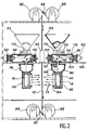
- FIG. 2 illustrates another embodiment of the device which is the subject of the invention.
- the elements identical to those in FIG. 1 have the same reference numbers.
- the substrate 12 for example a carbon fiber
- the aluminum foil 84 which protects the virgin fiber is wound on a coil 86 while 'A coil 88 emits the aluminum foil used to protect the impregnated fiber.
- the substrate 12 passes through a degassing oven 92 before arriving at the crucible.
- the crucible 18 and the reflectors 26 have windows allowing the passage of steam (arrows 13).
- a heating device (not shown) keeps the reflectors 94 at a temperature above the evaporation temperature of the material.
- the vapors emitted are well directed towards the substrate, which improves the yield of the deposit.
- reflectors such as 94 can also be used with the embodiment of FIG. 1.
- the crucible 18 has an opening in its upper part which puts it in communication with a chamber 96. This communicates, at its upper part, with the interior of a housing 98.
- Two electromagnets 100 and 102 whose role will be described below, are fixed to the walls of the housing 98. The latter as well as the two electromagnets are placed on a support 104 provided inside the vacuum enclosure.
- the chamber 96 and the crucible 18 are located under the support 104.
- the opening provided in the upper part of the crucible 18 can be closed by a conical plug 40. This is connected, by a cable 106 passing over a pulley or an angle gear 108, to the core 101 of the electromagnet 100 .
- the funnel-shaped powder container 50 is placed outside the housing 98 and above the latter. It is equipped at its lower part with a system for stopping the supply of magnesium 110 and communicates with the interior of the housing 98 by an orifice which can be closed by a valve 112. This valve can pivot around a axis 114 and it is connected by a cable 116 passing over a pulley 118 to the core 103 of the electromagnet 102. A return spring (not shown) returns the valve 112 to the closed position.
- the orifices making the reservoir 50 communicate with the housing 98, the housing 98 with the chamber 96 and the latter with the crucible 18 are located on the same vertical line.
- the operation of the device illustrated in FIG. 2 is as follows: At the start, the plug 40 and the valve 112 are in the closed position, that is to say that the cores 101 and 103 of the electromagnets 100 and 102 are moved to the left by looking at FIG. 2. In this situation, the electromagnet 100 is energized and electromagnet 102 is not.
- the plug 40 can be biased in the open position by a return spring (not shown).
- the electromagnet 102 is activated: the core 103 moves to the right while looking at the figure and the cable 116 rotates the valve 112 against the force exerted by its return spring.
- the electromagnet 100 is then de-energized so that the core 101 moves to the right, looking at the figure, causing the plug 40 to open under the effect of its return spring.
- the electromagnet 102 is de-energized and the return spring of the valve 112 returns it to the closed position.
- the electromagnet 100 is excited so that the core 101 is moved to the left while looking at the drawing, which has the effect of bringing the plug 40 in the closed position. At the end of a determined time, the cycle is restarted.
- a device like that which is illustrated in FIG. 1 was used as a source of evaporation of magnesium in an apparatus making it possible to prepare a "prepreg", that is to say a fibrous semi-product constituted, in this example , carbon fibers spread and then coated with magnesium by PVD (vapor deposition).
- the magnesium powder grains used had a practically spherical shape and an average diameter of 0.5 mm.
- Such a device can operate for as long as desired, the stopping occurring only when the entire substrate 12 has passed past the crucible 18 or when the powder reserve of the funnel 50 has been used up. After disassembly, no metal deposit or beginning of plugging was observed at the level of the supply valve 40, nor at the level of the neck 46. It was thus possible to produce several hundred meters of prepreg of carbon fibers coated with magnesium with no maintenance operation on the evaporation systems and with a rate of high production.
- the device which is the subject of the invention has particularly advantageous advantages over the devices of the prior art, the main one of which is to have a very high efficiency, generally close to 100%, and in any case greater than 50%.
- the crucible is closed by the supply valve 40 once the desired amount of powder is introduced and, on the other hand, the fact that the grid 32 has orifices of very small diameter allowing the passage of steam and preventing the passage of grains.
- the grid 32 has orifices of very small diameter allowing the passage of steam and preventing the passage of grains.
- the quantity of metal introduced at each opening can be adjusted as desired.
- the parts of the device in contact with the metal powder that is to say essentially the funnels 44 and 50 and the plate 54, are at a temperature lower than that of the crucible, and therefore at a temperature lower than that which can cause the metal to evaporate. This condition is necessary because, if it were not fulfilled, there would be an agglomeration of particles prejudicial to their transfer to the crucible.
- the invention is not limited to the sole embodiments which have just been described here, but that one can imagine variants without thereby departing from the scope of the invention.
- the skilled person can vary the shape and dimensions of the crucible, as well as the heating means thereof, and / or vary the number of reflectors depending on the conditions of use.
- the means for feeding the metal powder crucible if two embodiments have been described which are simple and practical, it would not go beyond the scope of the invention either by using another feeding system, provided that it allows intermittent feeding of the crucible. It is also possible to use any suitable means for fixing or maintaining the various elements of the device inside the enclosure, in particular the crucible, the reflectors, the funnels and the plate 54 control system.
- this device can be used regardless of the form in which the metal, powder, granules, beads or chips are present. It can be used whatever the metal to be deposited and whatever the substrate, for example a fibrous prepreg consisting of multi-strand fibers of carbon or silicon carbide previously spread, then metallized under vacuum.
Landscapes
- Chemical & Material Sciences (AREA)
- Chemical Kinetics & Catalysis (AREA)
- Engineering & Computer Science (AREA)
- Materials Engineering (AREA)
- Mechanical Engineering (AREA)
- Metallurgy (AREA)
- Organic Chemistry (AREA)
- Physical Vapour Deposition (AREA)
- Vaporization, Distillation, Condensation, Sublimation, And Cold Traps (AREA)
Claims (8)
- Anlage zum Verdampfen eines Metalls, die in einer Vakuumhülle verwendbar ist, mit:- einem Tiegel (18),- Vorrichtungen zum Einführen des Metalls (52) in Zustand von Teilchen in den Tiegel (18); und- Vorrichtungen (20) zum Bewirken der Verdampfung des Metalls (52), sobald es sich in dem Tiegel (18) befindet, dadurch gekennzeichnet, daß:- der Tiegel (18) geschlossen ist und in einer seiner Wände wenigstens eine Verdampfungsöffnung umfaßt, deren Ausmaße hinreichend klein sind, damit die in dem Tiegel vorhandenen Metallteilchen nicht entweichen können;- die Einführungsvorrichtungen umfassen:. eine Versorgungsöffnung, die von der Verdampfungsöffnung verschieden ist und die in einer Wand des Tiegels (18) vorgesehen ist und wenigstens teilweise während einer vorgegebenen Zeitdauer verschlossen werden kann;. ein zwischen einer Verschlußposition, in der es die Versorgungsöffnung des Tiegels (18) verschließt, und einer Öffnungsposition verschiebbares Ventil (40);. einen Behälter (50), der in einem bestimmten Abstand von dem Tiegel angeordnet ist und eine den Durchgang des Metalls (52) ermöglichende Öffnung besitzt;. Führungsvorrichtungen (44) für das Metall (52) von dem Behälter (50) zum Tiegel (18);. einen zwischen einer Verschlußposition, in der er die Öffnung des Behälters (50) verschließt, und einer Öffnungsposition verschiebbaren Verschluß (54); und. Vorrichtungen zum Steuern des Öffnens und Schließens des Ventils (40) und des Verschlusses (54).
- Anlage nach Anspruch 1, dadurch gekennzeichnet, daß der Tiegel (18) in einer seiner Wände ein von einem Gitter (32) geschlossenes Fenster besitzt, dessen Maschen hinreichend kleine Ausmaße besitzen, damit die in dem Tiegel vorhandenen Metallteilchen nicht entweichen können, wobei die Maschen des Gitters eine Anordnung von Verdampfungsöffnungen bilden.
- Anlage nach Anspruch 1, dadurch gekennzeichnet, daß die Steuerungsvorrichtungen so betätigt werden, daß sie das gleichzeitige Öffnen und Verschließen des Ventils (40) und des Verschlusses (54) bewirken.
- Anlage nach Anspruch 3, dadurch gekennzeichnet, daß, während sich der Verschluß (54) über dem Ventil (40) befindet, die Steuerungsvorrichtungen umfassen:- eine mechanische Verbindung (42) zwischen dem Vorschluß (42) und dem Stopfen (40);- einen starren Arm (56), an dem der Verschluß (54) montiert ist, wobei dieser Arm um eine Achse (58) schwenken kann; und- Vorrichtungen (62) zum Schwenken dieses Arms (56).
- Anlage nach Anspruch 4, dadurch gekennzeichnet, daß die Schwenkvorrichtungen umfassen:- wenigstens einen Elektromagneten (66) mit einem zwischen zwei Positionen beweglichen Kern (68); und- einem starren, mit diesem Kern (68) verbundenen Schaft (72), der auch mit einem mit dem Arm (56) verbunden Teil (60) über eine gelenkige Verbindung (74) verbunden ist, die sich in einem bestimmten Abstand von der Achse (58) befindet.
- Anlage nach Anspruch 1, dadurch gekennzeichnet, daß die Steuerungsvorrichtungen so betätigt werden, daß das Öffnen und Schließen des Ventils (40) von dem des Verschlusses unabhängig sind.
- Anlage nach Anspruch 6, dadurch gekennzeichnet, daß die Steuerungsvorrichtungen umfassen:- Vorrichtungen zum Rückführen des Ventils (40) in seine Öffnungsposition;- einen ersten Elektromagneten (100) mit einem zwischen einer ersten und einer zweiten Position beweglichen Kern (101);- eine erste mechanische Verbindung (106) zwischen dem Ventil und dem Kern (101) des ersten Elektromagneten (100), wobei die Erregung des letzteren die Bewegung seines Kerns und der ersten mechanischen Verbindung in der Richtung, die den Verschluß des Ventils (40) bewirkt, nach sich zieht;- Vorrichtungen zum Rückführen des Verschlusses (112) in seine Verschlußposition;- einen zweiten, von dem ersten verschiedenen Elektromagneten (102) mit einem zwischen einer ersten und einer zweiten Position beweglichen Kern (103); und- eine zweite mechanische Verbindung (116) zwischen dem Verschluß und dem Kern (103) des zweiten Elektromagneten (102), wobei die Erregung des letzteren die Bewegung seines Kerns und der zweiten mechanischen Verbindung in der Richtung, die die Öffnung des Verschlusses (112) bewirkt, nach sich zieht.
- Anlage nach Anspruch 1, dadurch gekennzeichnet, daß sie außerdem umfaßt:- eine Anordnung von Reflektoren (94), die derart außerhalb des Tiegels um die Verdampfungsöffnung (18) angeordnet sind, daß sie die ausgesandten Dämpfe in eine bestimmte Richtung richten; und- Vorrichtungen, um diese Reflektoren (94) auf einer Temperatur oberhalb der Verdampfungstemperatur des Metalls zu halten.
Priority Applications (1)
| Application Number | Priority Date | Filing Date | Title |
|---|---|---|---|
| AT88400522T ATE79417T1 (de) | 1987-03-06 | 1988-03-04 | Anlage zur kontinuierlichen vakuumverdampfung eines metalls. |
Applications Claiming Priority (2)
| Application Number | Priority Date | Filing Date | Title |
|---|---|---|---|
| FR8703092A FR2611746B1 (fr) | 1987-03-06 | 1987-03-06 | Dispositif d'evaporation sous vide d'un metal en continu |
| FR8703092 | 1987-03-06 |
Publications (2)
| Publication Number | Publication Date |
|---|---|
| EP0283374A1 EP0283374A1 (de) | 1988-09-21 |
| EP0283374B1 true EP0283374B1 (de) | 1992-08-12 |
Family
ID=9348693
Family Applications (1)
| Application Number | Title | Priority Date | Filing Date |
|---|---|---|---|
| EP88400522A Expired - Lifetime EP0283374B1 (de) | 1987-03-06 | 1988-03-04 | Anlage zur kontinuierlichen Vakuumverdampfung eines Metalls |
Country Status (6)
| Country | Link |
|---|---|
| US (1) | US4880960A (de) |
| EP (1) | EP0283374B1 (de) |
| AT (1) | ATE79417T1 (de) |
| DE (1) | DE3873568T2 (de) |
| ES (1) | ES2034288T3 (de) |
| FR (1) | FR2611746B1 (de) |
Families Citing this family (19)
| Publication number | Priority date | Publication date | Assignee | Title |
|---|---|---|---|---|
| DE10256038A1 (de) * | 2002-11-30 | 2004-06-17 | Applied Films Gmbh & Co. Kg | Bedampfungsvorrichtung |
| DE102004041854B4 (de) * | 2004-04-27 | 2008-11-13 | Von Ardenne Anlagentechnik Gmbh | Verfahren und Vorrichtung zur thermischen Vakuumbeschichtung |
| WO2006043723A1 (ja) * | 2004-10-21 | 2006-04-27 | Futaba Corporation | 蒸発源装置 |
| DE502005001749D1 (de) * | 2005-07-28 | 2007-11-29 | Applied Materials Gmbh & Co Kg | Bedampfervorrichtung |
| EP1752555A1 (de) | 2005-07-28 | 2007-02-14 | Applied Materials GmbH & Co. KG | Verdampfervorrichtung |
| ITMI20060444A1 (it) * | 2006-03-13 | 2007-09-14 | Getters Spa | Uso di composizioni magnesio-rame per l'evaporazione di magnesio e dispensatori di magnesio |
| US20090020070A1 (en) * | 2007-07-19 | 2009-01-22 | Michael Schafer | Vacuum evaporation apparatus for solid materials |
| TWI564427B (zh) * | 2009-12-18 | 2017-01-01 | 財團法人工業技術研究院 | 聚對二甲苯薄膜的形成方法 |
| EP2369033A1 (de) | 2010-03-26 | 2011-09-28 | Saint-Gobain Glass France | Verfahren zum Nachfüllen einer Verdampferkammer |
| EP2371991B1 (de) | 2010-03-26 | 2013-01-30 | Saint-Gobain Glass France | Verfahren zum diskontinuierlichen Nachfüllen einer Selenverdampferkammer |
| EP2369034B1 (de) | 2010-03-26 | 2013-01-30 | Saint-Gobain Glass France | Verfahren zum Nachfüllen einer Selenverdampferkammer |
| US10184168B2 (en) * | 2015-01-20 | 2019-01-22 | Kennametal Inc. | IMC evaporator boat-thermal insulation cartridge assembly |
| KR102098455B1 (ko) * | 2017-12-26 | 2020-04-07 | 주식회사 포스코 | 연속 증착 장치 및 연속 증착 방법 |
| KR20210074343A (ko) * | 2018-12-04 | 2021-06-21 | 어플라이드 머티어리얼스, 인코포레이티드 | 재료를 증발시키기 위한 증발 장치 및 증발 장치를 이용하여 재료를 증발시키기 위한 방법 |
| WO2020194631A1 (ja) * | 2019-03-27 | 2020-10-01 | シャープ株式会社 | 蒸着装置 |
| DE102019110950A1 (de) | 2019-04-29 | 2020-10-29 | Kennametal Inc. | Hartmetallzusammensetzungen und deren Anwendungen |
| DE102020118015A1 (de) * | 2020-07-08 | 2022-01-13 | Thyssenkrupp Steel Europe Ag | Beschichtungsvorrichtung zum Ablagern eines Beschichtungsmaterials auf einem Substrat |
| DE102021100060A1 (de) | 2021-01-05 | 2022-07-07 | Thyssenkrupp Steel Europe Ag | Beschichtungsanordnung |
| EP4547886A4 (de) * | 2022-07-01 | 2026-05-20 | China Triumph Int Eng Co Ltd | Vorrichtung zum verdampfen eines beschichtungsmaterials und verwendung der vorrichtung |
Family Cites Families (7)
| Publication number | Priority date | Publication date | Assignee | Title |
|---|---|---|---|---|
| BE515457A (de) * | 1951-11-10 | |||
| US2793609A (en) * | 1953-01-26 | 1957-05-28 | British Dielectric Res Ltd | Means for the deposition of materials by evaporation in a vacuum |
| GB900205A (en) * | 1957-07-15 | 1962-07-04 | Richard John Fletcher | Improvements in and relating to sources for the evaporation of metals and other materials under vacuum |
| GB1052595A (de) * | 1964-06-30 | |||
| US3563202A (en) * | 1969-06-25 | 1971-02-16 | Pennwalt Corp | Mobile vbaporative firing source |
| US4395179A (en) * | 1976-03-10 | 1983-07-26 | Davy Inc. | Apparatus and method for charging material into a receptacle |
| DE2916080C2 (de) * | 1979-04-20 | 1984-12-06 | Kišinevskij Gosudarstvennyj universitet imeni V.I. Lenina, Kišinev | Verfahren zum Molekular-Aufdampfen von Halbleiterschichten und Vorrichtung zur Durchführung dieses Verfahrens |
-
1987
- 1987-03-06 FR FR8703092A patent/FR2611746B1/fr not_active Expired
-
1988
- 1988-03-04 EP EP88400522A patent/EP0283374B1/de not_active Expired - Lifetime
- 1988-03-04 ES ES198888400522T patent/ES2034288T3/es not_active Expired - Lifetime
- 1988-03-04 AT AT88400522T patent/ATE79417T1/de not_active IP Right Cessation
- 1988-03-04 DE DE8888400522T patent/DE3873568T2/de not_active Expired - Fee Related
- 1988-03-07 US US07/165,079 patent/US4880960A/en not_active Expired - Fee Related
Also Published As
| Publication number | Publication date |
|---|---|
| DE3873568D1 (de) | 1992-09-17 |
| ES2034288T3 (es) | 1993-04-01 |
| US4880960A (en) | 1989-11-14 |
| ATE79417T1 (de) | 1992-08-15 |
| DE3873568T2 (de) | 1993-03-11 |
| FR2611746B1 (fr) | 1989-06-30 |
| FR2611746A1 (fr) | 1988-09-09 |
| EP0283374A1 (de) | 1988-09-21 |
Similar Documents
| Publication | Publication Date | Title |
|---|---|---|
| EP0283374A1 (de) | Anlage zur kontinuierlichen Vakuumverdampfung eines Metalls | |
| CA2681329C (fr) | Procede de revetement d'un substrat et installation de depot sous vide d'alliage metallique | |
| WO2009047333A1 (fr) | Générateur de vapeur industriel pour le dépôt d'un revêtement d'alliage sur une bande métallique | |
| CH650275A5 (fr) | Appareil pour realiser le depot reactif d'un revetement d'oxyde sur un substrat. | |
| EP2367614B1 (de) | Vorrichtung zur abscheidung einer pulvermischung zur bildung eines objekts mit zusammensetzungsgradienten und darauf bezogenes verfahren | |
| FR2545007A1 (fr) | Procede et dispositif pour le revetement d'une piece par projection de plasma | |
| EP2199425A1 (de) | Industrieller Dampferzeuger zum Aufbringen einer Legierungsschicht auf einem Metallband (II) | |
| CA2631611C (fr) | Procede et un dispositif d'enduction metallique de fibres par voie liquide | |
| FR2868355A1 (fr) | Procede et appareil de fabrication de fibres revetues de polymere | |
| TW201132776A (en) | Apparatus for forming organic thin film and method for forming thin film of organic material | |
| FR2571484A1 (fr) | Procede et dispositif pour faire fondre progressivement du materiau en forme de barreau au moyen d'une bobine d'induction | |
| FR2551458A1 (fr) | Cellule de vaporisation pour depot sous vide de minces couches sur des supports | |
| EP0282410A2 (de) | Methode und Vorrichtung zum Imprägnieren eines länglichen Körpers | |
| EP2536863B1 (de) | Vorrichtung zur gewinnung von in einem flüssigverfahren mit einer dicken metallhülle überzogenen keramikfasern | |
| BE569893A (de) | ||
| FR2956412A1 (fr) | Vanne d'obturation a volume constant d'une source de depot en phase vapeur | |
| BE1008303A3 (fr) | Procede et dispositif pour la formation d'un revetement sur un substrat par pulverisation cathodique. | |
| FR3105037A1 (fr) | Traitement in situ de poudre pour fabrication additive en vue d’améliorer sa conductivité thermique et/OU électrique | |
| WO2021123572A1 (fr) | Traitement in situ de poudres pour fabrication additive | |
| FR2661847A1 (fr) | Procede de fabrication de pieces ou de revetements de pieces. | |
| FR2543165A1 (fr) | Procede et dispositif d'elaboration de couches composites, par superposition, en continu et en atmosphere controlee | |
| FR2579487A1 (fr) | Appareil pour reguler l'ecoulement de particules fines | |
| FR2876685A1 (fr) | Procede et dispositif de fabrication en continu de fils metalliques gaines de verre par alimentation de particules metalliques | |
| CH198728A (fr) | Procédé et appareil pour déposer une pellicule de matière sur un support par l'évaporation de cette matière dans le vide, à l'intérieur d'une chambre. | |
| FR2539325A1 (fr) | Dispositif d'alimentation en poudre pour appliquer des revetements resistant a l'usure sur des objets |
Legal Events
| Date | Code | Title | Description |
|---|---|---|---|
| PUAI | Public reference made under article 153(3) epc to a published international application that has entered the european phase |
Free format text: ORIGINAL CODE: 0009012 |
|
| AK | Designated contracting states |
Kind code of ref document: A1 Designated state(s): AT BE CH DE ES FR GB GR IT LI LU NL SE |
|
| 17P | Request for examination filed |
Effective date: 19890222 |
|
| 17Q | First examination report despatched |
Effective date: 19900726 |
|
| GRAA | (expected) grant |
Free format text: ORIGINAL CODE: 0009210 |
|
| AK | Designated contracting states |
Kind code of ref document: B1 Designated state(s): AT BE CH DE ES FR GB GR IT LI LU NL SE |
|
| PG25 | Lapsed in a contracting state [announced via postgrant information from national office to epo] |
Ref country code: IT Free format text: LAPSE BECAUSE OF FAILURE TO SUBMIT A TRANSLATION OF THE DESCRIPTION OR TO PAY THE FEE WITHIN THE PRESCRIBED TIME-LIMIT;WARNING: LAPSES OF ITALIAN PATENTS WITH EFFECTIVE DATE BEFORE 2007 MAY HAVE OCCURRED AT ANY TIME BEFORE 2007. THE CORRECT EFFECTIVE DATE MAY BE DIFFERENT FROM THE ONE RECORDED. Effective date: 19920812 Ref country code: AT Effective date: 19920812 Ref country code: GR Free format text: LAPSE BECAUSE OF FAILURE TO SUBMIT A TRANSLATION OF THE DESCRIPTION OR TO PAY THE FEE WITHIN THE PRESCRIBED TIME-LIMIT Effective date: 19920812 |
|
| REF | Corresponds to: |
Ref document number: 79417 Country of ref document: AT Date of ref document: 19920815 Kind code of ref document: T |
|
| REF | Corresponds to: |
Ref document number: 3873568 Country of ref document: DE Date of ref document: 19920917 |
|
| GBT | Gb: translation of ep patent filed (gb section 77(6)(a)/1977) | ||
| PG25 | Lapsed in a contracting state [announced via postgrant information from national office to epo] |
Ref country code: LI Effective date: 19930331 Ref country code: BE Effective date: 19930331 Ref country code: LU Free format text: LAPSE BECAUSE OF NON-PAYMENT OF DUE FEES Effective date: 19930331 Ref country code: CH Effective date: 19930331 |
|
| REG | Reference to a national code |
Ref country code: ES Ref legal event code: FG2A Ref document number: 2034288 Country of ref document: ES Kind code of ref document: T3 |
|
| PLBE | No opposition filed within time limit |
Free format text: ORIGINAL CODE: 0009261 |
|
| STAA | Information on the status of an ep patent application or granted ep patent |
Free format text: STATUS: NO OPPOSITION FILED WITHIN TIME LIMIT |
|
| 26N | No opposition filed | ||
| BERE | Be: lapsed |
Owner name: CENTRE NATIONAL D'ETUDES SPATIALES Effective date: 19930331 |
|
| REG | Reference to a national code |
Ref country code: CH Ref legal event code: PL |
|
| EAL | Se: european patent in force in sweden |
Ref document number: 88400522.4 |
|
| PGFP | Annual fee paid to national office [announced via postgrant information from national office to epo] |
Ref country code: SE Payment date: 19990301 Year of fee payment: 12 |
|
| PGFP | Annual fee paid to national office [announced via postgrant information from national office to epo] |
Ref country code: GB Payment date: 19990304 Year of fee payment: 12 Ref country code: ES Payment date: 19990304 Year of fee payment: 12 |
|
| PGFP | Annual fee paid to national office [announced via postgrant information from national office to epo] |
Ref country code: DE Payment date: 19990311 Year of fee payment: 12 |
|
| PGFP | Annual fee paid to national office [announced via postgrant information from national office to epo] |
Ref country code: FR Payment date: 19990330 Year of fee payment: 12 |
|
| PGFP | Annual fee paid to national office [announced via postgrant information from national office to epo] |
Ref country code: NL Payment date: 19990331 Year of fee payment: 12 |
|
| PG25 | Lapsed in a contracting state [announced via postgrant information from national office to epo] |
Ref country code: GB Free format text: LAPSE BECAUSE OF NON-PAYMENT OF DUE FEES Effective date: 20000304 |
|
| PG25 | Lapsed in a contracting state [announced via postgrant information from national office to epo] |
Ref country code: SE Free format text: LAPSE BECAUSE OF NON-PAYMENT OF DUE FEES Effective date: 20000305 |
|
| PG25 | Lapsed in a contracting state [announced via postgrant information from national office to epo] |
Ref country code: ES Free format text: LAPSE BECAUSE OF NON-PAYMENT OF DUE FEES Effective date: 20000306 |
|
| PG25 | Lapsed in a contracting state [announced via postgrant information from national office to epo] |
Ref country code: NL Free format text: LAPSE BECAUSE OF NON-PAYMENT OF DUE FEES Effective date: 20001001 |
|
| GBPC | Gb: european patent ceased through non-payment of renewal fee |
Effective date: 20000304 |
|
| EUG | Se: european patent has lapsed |
Ref document number: 88400522.4 |
|
| PG25 | Lapsed in a contracting state [announced via postgrant information from national office to epo] |
Ref country code: FR Free format text: LAPSE BECAUSE OF NON-PAYMENT OF DUE FEES Effective date: 20001130 |
|
| NLV4 | Nl: lapsed or anulled due to non-payment of the annual fee |
Effective date: 20001001 |
|
| REG | Reference to a national code |
Ref country code: FR Ref legal event code: ST |
|
| PG25 | Lapsed in a contracting state [announced via postgrant information from national office to epo] |
Ref country code: DE Free format text: LAPSE BECAUSE OF NON-PAYMENT OF DUE FEES Effective date: 20010103 |
|
| REG | Reference to a national code |
Ref country code: ES Ref legal event code: FD2A Effective date: 20010910 |