EP0283424A1 - Accouplement de surcharge - Google Patents
Accouplement de surcharge Download PDFInfo
- Publication number
- EP0283424A1 EP0283424A1 EP88630053A EP88630053A EP0283424A1 EP 0283424 A1 EP0283424 A1 EP 0283424A1 EP 88630053 A EP88630053 A EP 88630053A EP 88630053 A EP88630053 A EP 88630053A EP 0283424 A1 EP0283424 A1 EP 0283424A1
- Authority
- EP
- European Patent Office
- Prior art keywords
- ball
- disc
- diameter
- balls
- cavities
- Prior art date
- Legal status (The legal status is an assumption and is not a legal conclusion. Google has not performed a legal analysis and makes no representation as to the accuracy of the status listed.)
- Granted
Links
Images
Classifications
-
- F—MECHANICAL ENGINEERING; LIGHTING; HEATING; WEAPONS; BLASTING
- F16—ENGINEERING ELEMENTS AND UNITS; GENERAL MEASURES FOR PRODUCING AND MAINTAINING EFFECTIVE FUNCTIONING OF MACHINES OR INSTALLATIONS; THERMAL INSULATION IN GENERAL
- F16D—COUPLINGS FOR TRANSMITTING ROTATION; CLUTCHES; BRAKES
- F16D43/00—Automatic clutches
-
- F—MECHANICAL ENGINEERING; LIGHTING; HEATING; WEAPONS; BLASTING
- F16—ENGINEERING ELEMENTS AND UNITS; GENERAL MEASURES FOR PRODUCING AND MAINTAINING EFFECTIVE FUNCTIONING OF MACHINES OR INSTALLATIONS; THERMAL INSULATION IN GENERAL
- F16D—COUPLINGS FOR TRANSMITTING ROTATION; CLUTCHES; BRAKES
- F16D25/00—Fluid-actuated clutches
- F16D25/08—Fluid-actuated clutches with fluid-actuated member not rotating with a clutching member
- F16D25/082—Fluid-actuated clutches with fluid-actuated member not rotating with a clutching member the line of action of the fluid-actuated members co-inciding with the axis of rotation
-
- F—MECHANICAL ENGINEERING; LIGHTING; HEATING; WEAPONS; BLASTING
- F16—ENGINEERING ELEMENTS AND UNITS; GENERAL MEASURES FOR PRODUCING AND MAINTAINING EFFECTIVE FUNCTIONING OF MACHINES OR INSTALLATIONS; THERMAL INSULATION IN GENERAL
- F16D—COUPLINGS FOR TRANSMITTING ROTATION; CLUTCHES; BRAKES
- F16D43/00—Automatic clutches
- F16D43/02—Automatic clutches actuated entirely mechanically
- F16D43/20—Automatic clutches actuated entirely mechanically controlled by torque, e.g. overload-release clutches, slip-clutches with means by which torque varies the clutching pressure
- F16D43/202—Automatic clutches actuated entirely mechanically controlled by torque, e.g. overload-release clutches, slip-clutches with means by which torque varies the clutching pressure of the ratchet type
- F16D43/204—Automatic clutches actuated entirely mechanically controlled by torque, e.g. overload-release clutches, slip-clutches with means by which torque varies the clutching pressure of the ratchet type with intermediate balls or rollers
- F16D43/206—Automatic clutches actuated entirely mechanically controlled by torque, e.g. overload-release clutches, slip-clutches with means by which torque varies the clutching pressure of the ratchet type with intermediate balls or rollers moving axially between engagement and disengagement
Definitions
- the present invention relates generally to overload apparatus where the output is disengaged from the input in the event of reaching a predetermined overload torque level, particularly, in its preferred form to an overload clutch, and specifically, in its most preferred form to an overload single position clutch.
- the present invention solves this need in providing overload relief and solves the problems and disadvantages of prior apparatus by providing an overload apparatus including balls captured in ball carrying cavities of a first disc and for registry in or out of ball receiving cavities of a second disc.
- the ball carrying and ball receiving cavities have diameters less than the diameters of the balls and the ball receiving cavities have a diameter less than the diameter of the ball carrying cavities to bias ball cam out from the ball receiving cavities rather than the ball carrying cavities in the event of reaching a torque overload level.
- the balls are captured in the ball carrying cavities by a carrier ring having constant diameter apertures of a size for receipt of the balls and by a retaining plate having constant diameter apertures of a size less than the diameter of the balls.
- the carrier ring is sandwiched between the disc and the retaining plate with the balls extending through and beyond the apertures of the retaining plate.
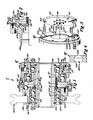
- Clutch A includes the stationary cylinder 10 formed with the internal annular surface 12 and the reduced diameter annular surface 14. Formed in the cylinder surface 14 is the annular recess 16 in which is positioned the O-ring 18.
- the cylinder 10 also includes the annular flange 20.
- the annular piston 22 formed with the major diameter portion 24 and the reduced diameter portion 26.
- the piston 22 is formed with the annular recess 28 in which is press fit the outer race 30 of the bearing 32.
- the inner race 34 of the bearing 32 is press fit on the rotatable hub 36 formed with the internal keyway 37.
- the outer surface of the piston portion 24 is formed with the annular recess 38 in which is positioned the O-ring 40 which makes sealing engagement with the cylinder 10.
- the O-ring 18 makes sealing engagement with the piston portion 26.
- the numeral 42 designates an inlet which allows fluid pressure to enter the cylinder by conventional means.
- the outer race 44 of bearing 46 is mounted within the cylinder flange 20 and the inner race 48 is press fit upon the splined sleeve 50 of the circular drive ring 52 which is the preferred form of an interface disc of clutch A according to the teachings of the present invention.
- the sleeve 50 terminates in the radially disposed annular flange 54. Formed adjacent but radially inward of the periphery and extending generally perpendicularly to the inner face of the annular flange 54 and axially through annular flange 54 are the five spaced ball-receiving cavities 58, 60, 62, 64, and 66 having generally cylindrical shape.
- the flange 54 of the drive ring 52 is formed with a central opening 68 which coincides with the inner surface of the sleeve 50, and formed on the inner surface of the flange and the sleeve are the splines 70 which slidably engage with the splines 72 formed on the hub 36 thereby allowing the drive ring to slide axially on the hub.
- the inner race 48 of the bearing 46 is press fit in the annular recess 74 of the sleeve 50 of the drive ring and the race 48 abuts the shoulder 76 of the drive ring formed by the recess 74.
- the drive ring 52 is urged against axial movement by means of a multiplicity of coil springs 78 mounted in bores 80 formed in the sleeve 50, the outer ends of the springs abutting the back up washer 82 mounted on the hub 36 and the inner ends of the springs abutting the inner ends of the bores 80.
- the washer 82 is mounted in the recess 84 formed on the hub and abuts the shoulder 86 formed by the recess 84.
- the mount 96 has formed therein the annular recess 110 in which the outer races 112 and 114 of the bearings 116 and 118, respectively, are press fit and held therein by the lock ring 120.
- the inner races 122 and 124 are press fit in the recess 84 and abutting the washer 82 and held in position by the lock ring 126.
- Mount 96 includes the integrally formed interface disc of clutch A according to the preferred teachings of the present invention and has formed therein the annular recess 128 on which a sheave 162 may be mounted for driving of the same.
- sheave 162 includes an inner opening 164 having a size and shape complementary to and for receipt on mount 96.
- Sheave 162 is held in the same rotational position as mount 96 by bolts 166 axially extending through sheave 162 and threadably received in mount 96. It can then be appreciated that mount 96 may include a break away connection of the type shown and described in U.S. Patent 4,635,768.
- balls 100b, 102b, 104b, 106b, and 108b are provided mounted to the inner face 99 of mount 96 which is arranged substantially adjacent and parallel to the inner face of drive ring 52.
- balls 100b-108b are mounted by complementary axially extending, ball carrying cavities or socket portions 100a and ball cage 88.
- Socket portions 100a extend generally perpendicularly from inner face 99 of mount 96 and are generally cylindrical in shape having a first circular end 109 having a diameter less than balls 100b-108b and a length sufficient such that balls 100b-108b seated in ends 109 of socket portions 100a do not engage the opposite end of socket portions 100a.
- the diameters of socket portions 100a are greater than the diameters of ball-receiving cavities 58-66.
- ball cage 88 for capturing balls 100b-108b within socket portions 100a is formed from a ball seat 150 having a first face 152 for abutment with the inner face 99 of mount 96 and having an opposite face 154.
- Ball seat 150 includes apertures 100c corresponding to socket portions 100a for receiving and holding balls 100b-108b in socket portions 100a.
- apertures 100c include a first, cylindrical portion 156 extending from face 152 and having a diameter generally equal to but slightly larger than the diameter of balls 100b-108b and a second portion 158 extending from portion 156 and terminating in face 154.
- portion 158 is frustoconical in shape having a diameter equal to the diameter of portion 156 at their intersections and decreasing to a diameter at face 154 which is less than the diameter of balls 100b-108b.
- the respective lengths of portions 156 and 158 should then allow balls 100b-108b to be received in socket portions 100a and apertures 100c with face 152 abutting with face 99 of mount 96 and with balls 100b-108b being generally captured in a seating manner with socket portions 100a and specifically allowing balls 100b-108b to roll but not allowing balls 100b-108b to clatter during rotation of mount 96 and disengagement from drive ring 52.
- the balls 100b-108b are mounted on the flange mount 96 by placing the balls first in the apertures 100c. Next the combination and the balls thereof are placed in the partial complementary socket portions 100a and ball seat 150 secured to the mount 96 by screws 160 thereby mounting the balls on the mount 96. Screws 160 may be received in openings 161 having countersunk entries to allow screws 160 to be located circumferentially intermediate socket portions 100a in the interface area of balls 100b-108b and not interfere with the inner face of drive ring 52.
- ball cage 88 is formed from a carrier ring 168 and a retaining plate 170.
- Carrier ring 168 includes apertures 100d corresponding to socket portions 100a and having diameters generally equal to but slightly larger than the diameter of balls 100b-108b for receiving balls 100b-108b therein.
- Retaining plate 170 includes apertures 100e, 102e, 104e, 106e, and 108e corresponding to socket portions 100a and apertures 100d and having a diameter less than the diameter of balls 100b-108b.
- Carrier ring 168 is sandwiched between inner face 99 of mount 96 and plate 170 and the combination is secured to mount 96 by screws 172.
- carrier ring 168 should then allow balls 100b-108b to be received in socket portions 100a and apertures 100d and captured therein by plate 170 with balls 100b-108b extending through and beyond apertures 100e-108e of plate 170 and not allowing balls 100b-108b to clatter during rotation of mount 96 and disengagement from drive ring 52.
- the hub 36 is keyed to the shaft of a motor not shown whereby the drive ring 52 is rotated. Fluid pressure is introduced into the inlet 42 thereby causing the cylinder 10 to move axially and cause the drive ring 52 to also move axially as it rotates whereby the cavities 58-66 seek register with balls 100b-108b. Generally speaking, with register of the cavities with the balls, the mount is rotated. Torque force is not created until full registry of the balls and once there is engagement all torque is taken by the balls. It will be seen that all five balls are either in or out of engagement and when not in engagement there is planar support for the drive ring.
- clutch A in an engaged position includes a torque overload level where balls 100b-108b cam out of cavities 58-66.
- This torque overload level depends upon several factors. First, this torque overload level is dependent upon the spring and fluid pressure forces placed upon drive ring 52 by springs 78 and cylinder 10, which then depend upon various design parameters. However, it should be also appreciated that for the same unit of clutch A according to the teachings of the present invention, the torque overload level may be remotely varied by simply varying the fluid pressure introduced into inlet 42 such as by the utilization of a variable pressure valve.
- this torque overload level is dependent upon the sizes and interrelationships of balls 100b-108b and cavities 100a and 58-66. It can then be appreciated that the camming action of balls 100b-108b out of cavities 58-66 is directly dependent upon the depth that balls 100b-108b extend into cavities 58-66, with the greater depth, i.e. approaching the equator of balls 100b-108b requiring the greatest torque level to remove balls 100b-108b from cavities 58-66 and with lesser depths requiring lesser torque levels to remove balls 100b-108b from cavities 58-66.
- torque overload level may then be varied by the choice of the sizes of balls 100b-108b and cavities 100a and cavities 58-66; however to allow standardization of components, it can be appreciated that clutch A can be of a standard design aside from the diameters of cavities 58-66 which may be drilled to the size to achieve the desired torque overload level according to the particular application.
- clutch A achieves interface antibacklash features as the result of the preferred construction.
- Backlash is the loss of motion due to play in the parts during reversal in motion direction.
- cavities 58-66 and 100a have diameters less than balls 100b-108b and have lengths such that balls 100b-108b do not touch the ends as well as the sidewalls of cavities 58-66 and 100a.
- cavities 58-66 and 100a include only a small chamfer necessary to protect the corners during heat treating.
- the ball cage 88 formed from carrier ring 168 and plate 170 is further advantageous in regard to manufacture. Specifically, it can then be appreciated that apertures 100d and 100e-108e can be easily repeated in manufacture as they are through apertures which do not require depth control of any nature to be held for tolerance purposes. Thus, the lack of depth tolerances greatly reduce the cost of manufacture while still meeting torque tolerances.
- the relationships taught by the present invention for the diameters of cavities 58-66 and 100a are advantageous. Particularly, since the diameters of cavities 100a-108a are larger than the diameters of cavities 58-66, balls 100b-108b are received or seated at a greater depth in cavities 100a than in cavities 58-66. As set forth, the greater the depth of receipt of balls 100b-108b, the greater the level of the torque required for balls 100b-108b to cam out of the cavities. Therefore, greater torque is required to cam balls 100b-108b out of cavities 100a than to cam balls 100b-108b out of cavities 58-66.
- balls 100b-108b will tend always to cam out of cavities 58-66 such that minimal torque load is placed upon ball cage 88 and its securement to mount 96.
- a major purpose of ball cage 88 is to retain balls 100b-108b adjacent to mount 96 during disengagement, especially in a vertical clutch orientation.
- a diameter of 0.456 inches (1.158 cm) for cavities 58-66 and a diameter of 0.484 inches (1.229 cm) for cavities 100a has been found to achieve the desired ball cam out characteristics for balls 100b-108b having diameters of 0.500 inches (1.270 cm).
- the side of the interface which balls 100b-108b are released from can be biased by design in the selection of the diameters of the cavities.
- a crisp release may be achieved in the event of reaching a torque overload level according to the teachings of the present invention.
- prior overload apparatus utilized springs to bias the interface discs together.
- the compression of the springs result in an increase in force preventing separation of the interface discs, such that "toe hold” may exist to prevent or delay release.
- Utilizing clutch A according to the teachings of the present invention having a pressure self relieving regulator does not result in increasing interface separation force as the interface discs separate resulting in a crisp release in the event of reaching a torque overload level without the "toe hold" effect of prior spring biased overload apparatus.
- a limit switch may be mechanically secured to drive ring 52 to dump fluid from inlet 42 in the event of drive ring 52 movement as the result of overload to further assist a crisp release and to prevent automatic reset of clutch A according to the teachings of the present invention.
- an overload apparatus may be constructed according to the teachings of the present invention which is not of the clutching variety.
Landscapes
- General Engineering & Computer Science (AREA)
- Engineering & Computer Science (AREA)
- Mechanical Engineering (AREA)
- One-Way And Automatic Clutches, And Combinations Of Different Clutches (AREA)
- Power Steering Mechanism (AREA)
- Control Of Electric Motors In General (AREA)
- Hydraulic Clutches, Magnetic Clutches, Fluid Clutches, And Fluid Joints (AREA)
- Confectionery (AREA)
- Saccharide Compounds (AREA)
- Sink And Installation For Waste Water (AREA)
- Electrical Discharge Machining, Electrochemical Machining, And Combined Machining (AREA)
- Centrifugal Separators (AREA)
- Compositions Of Oxide Ceramics (AREA)
- Lock And Its Accessories (AREA)
Priority Applications (1)
| Application Number | Priority Date | Filing Date | Title |
|---|---|---|---|
| AT88630053T ATE56509T1 (de) | 1987-03-20 | 1988-03-17 | Ueberlastungskupplung. |
Applications Claiming Priority (2)
| Application Number | Priority Date | Filing Date | Title |
|---|---|---|---|
| US07/028,247 US4770281A (en) | 1987-03-20 | 1987-03-20 | Overload apparatus |
| US28247 | 1987-03-20 |
Publications (2)
| Publication Number | Publication Date |
|---|---|
| EP0283424A1 true EP0283424A1 (fr) | 1988-09-21 |
| EP0283424B1 EP0283424B1 (fr) | 1990-09-12 |
Family
ID=21842383
Family Applications (2)
| Application Number | Title | Priority Date | Filing Date |
|---|---|---|---|
| EP88903562A Pending EP0340249A1 (fr) | 1987-03-20 | 1988-03-17 | Dispositif de surcharge |
| EP88630053A Expired - Lifetime EP0283424B1 (fr) | 1987-03-20 | 1988-03-17 | Accouplement de surcharge |
Family Applications Before (1)
| Application Number | Title | Priority Date | Filing Date |
|---|---|---|---|
| EP88903562A Pending EP0340249A1 (fr) | 1987-03-20 | 1988-03-17 | Dispositif de surcharge |
Country Status (13)
| Country | Link |
|---|---|
| US (1) | US4770281A (fr) |
| EP (2) | EP0340249A1 (fr) |
| JP (1) | JPH0735827B2 (fr) |
| KR (1) | KR930011878B1 (fr) |
| AT (1) | ATE56509T1 (fr) |
| AU (1) | AU606942B2 (fr) |
| CA (1) | CA1304304C (fr) |
| DE (1) | DE3860580D1 (fr) |
| DK (1) | DK167411B1 (fr) |
| ES (1) | ES2017544B3 (fr) |
| GR (1) | GR3001154T3 (fr) |
| IE (1) | IE61276B1 (fr) |
| WO (1) | WO1988007146A1 (fr) |
Cited By (2)
| Publication number | Priority date | Publication date | Assignee | Title |
|---|---|---|---|---|
| DE19713875A1 (de) * | 1997-04-04 | 1998-10-15 | Voith Turbo Kg | Kupplung mit mechanischer Drehmomentübertragung |
| EP0875687A1 (fr) * | 1997-04-30 | 1998-11-04 | O.M.C. S.n.c. di DANTE CAVALLI & C. | Embrayage limiteur de couple |
Families Citing this family (20)
| Publication number | Priority date | Publication date | Assignee | Title |
|---|---|---|---|---|
| DE3871310D1 (de) * | 1987-10-01 | 1992-06-25 | British Autogard | Schaltbare kupplung. |
| US4858740A (en) * | 1988-03-10 | 1989-08-22 | Hansen Quinten A | Overload release clutch |
| US4969301A (en) * | 1989-06-14 | 1990-11-13 | Aec-Able Engineering Company, Inc. | Relatchable launch restraint mechanism for deployable booms |
| US4934500A (en) * | 1989-09-11 | 1990-06-19 | Horton Manufacturing Co., Inc. | Fluid pressure releasing device for overload apparatus |
| US5355983A (en) * | 1993-07-07 | 1994-10-18 | Horton Manufacturing Co., Inc. | Electronically controlled rotational control apparatus |
| US5601169A (en) * | 1994-02-18 | 1997-02-11 | British Autogard Limited | Fluid pressure overload release clutch |
| US5896968A (en) * | 1997-04-22 | 1999-04-27 | The Carlson Company, Inc. | Torque limiting mechanism |
| CA2426354A1 (fr) * | 2003-04-25 | 2004-10-25 | Gemofor Inc. | Embrayage de surcharge pour proteger une ligne de transmission de puissance contre les surcharges |
| US7104382B2 (en) * | 2004-10-21 | 2006-09-12 | Kit Masters Inc. | Clutch system |
| US7438169B2 (en) | 2004-10-21 | 2008-10-21 | Kit Masters Inc. | Clutch system |
| US8100239B2 (en) * | 2008-01-18 | 2012-01-24 | Kit Masters Inc. | Clutch device and methods |
| JP4674826B2 (ja) * | 2008-04-15 | 2011-04-20 | 株式会社ツバキエマソン | 過負荷保護装置 |
| FR2931131B1 (fr) * | 2008-05-19 | 2010-08-13 | Eurocopter France | Dispositif d'accouplement escamotable et verin de trim associe |
| WO2010056830A2 (fr) | 2008-11-12 | 2010-05-20 | Horton, Inc. | Embrayage à deux vitesses et kit de mise à niveau |
| US8109375B2 (en) * | 2009-05-07 | 2012-02-07 | Kit Masters Inc. | Clutch systems and methods |
| US9046137B2 (en) | 2010-01-22 | 2015-06-02 | Kit Masters Inc. | Fan clutch apparatus and methods |
| US8360219B2 (en) | 2010-04-26 | 2013-01-29 | Kit Masters, Inc. | Clutch system and methods |
| US9417754B2 (en) | 2011-08-05 | 2016-08-16 | P4tents1, LLC | User interface system, method, and computer program product |
| JP5441281B2 (ja) * | 2012-07-11 | 2014-03-12 | 株式会社ユニバーサルエンターテインメント | 遊技機 |
| CN112908763A (zh) * | 2021-04-06 | 2021-06-04 | 四川华能康定水电有限责任公司 | 一种万向行程开关触头 |
Citations (9)
| Publication number | Priority date | Publication date | Assignee | Title |
|---|---|---|---|---|
| FR1113209A (fr) * | 1954-10-26 | 1956-03-26 | Limiteur de couple pour organes de transmission | |
| FR1219324A (fr) * | 1958-12-23 | 1960-05-17 | Autoset Production Ltd | Montage pour bille porte-charge |
| FR1432978A (fr) * | 1965-04-21 | 1966-03-25 | Ingersoll Rand Co | Embrayage |
| US3260541A (en) * | 1962-03-23 | 1966-07-12 | Hypro Inc | Coupler for power take-off |
| US3760916A (en) * | 1972-04-07 | 1973-09-25 | Horton Mfg Co Inc | Single position fluid operated clutch |
| FR2534333A1 (fr) * | 1982-10-06 | 1984-04-13 | Peters Ag Claudius | Accouplement a rotation debrayable |
| FR2555269A1 (fr) * | 1983-11-18 | 1985-05-24 | Thomson Csf | Dispositif limiteur de couple a embrayage a billes |
| US4635768A (en) * | 1985-01-22 | 1987-01-13 | Horton Manufacturing Co., Inc. | Clutch having an output with break away connection |
| US4645372A (en) * | 1984-10-01 | 1987-02-24 | Matsui-Walterschield Ltd. | Power transmitting coupling |
Family Cites Families (29)
| Publication number | Priority date | Publication date | Assignee | Title |
|---|---|---|---|---|
| US1274722A (en) * | 1918-01-02 | 1918-08-06 | Paul H Lacey | Automatic safety device for preventing overload on motors and other driving elements. |
| US2401992A (en) * | 1944-07-19 | 1946-06-11 | George A Waller | Overload clutch |
| US2475518A (en) * | 1946-06-03 | 1949-07-05 | Milwaukee Electric Tool Corp | Torque release tool for screwthreaded units |
| US2508061A (en) * | 1946-08-27 | 1950-05-16 | Lipe Rollway Corp | Overload release clutch |
| US2683362A (en) * | 1953-03-12 | 1954-07-13 | Le Roi Company | Overriding clutch |
| US2837190A (en) * | 1954-11-16 | 1958-06-03 | Walter L Blakeslee | Overload release clutch |
| US2969132A (en) * | 1955-12-09 | 1961-01-24 | Harold H Stewart | Torque limiting devices |
| US3070393A (en) * | 1956-08-08 | 1962-12-25 | Deere & Co | Coupling for power take off shaft |
| DE1101059B (de) * | 1957-02-16 | 1961-03-02 | Kocks Gmbh Friedrich | UEberlastungskupplung |
| US3050321A (en) * | 1957-11-15 | 1962-08-21 | John R Howe | Auxiliary drive clutch mechanism |
| DE1102514B (de) * | 1958-04-30 | 1961-03-16 | Heinrich Gensheimer Jun | Klemmrollengesperre fuer Schaltwerksgetriebe |
| US3177740A (en) * | 1963-10-28 | 1965-04-13 | Eugene S Firestone | Indexing fixture |
| GB1044355A (en) * | 1964-05-27 | 1966-09-28 | Nat Res Dev | Improved indexing devices |
| US3319753A (en) * | 1964-09-08 | 1967-05-16 | Fisher & Ludlow Ltd | Overload clutches |
| US3298488A (en) * | 1964-09-29 | 1967-01-17 | James A Mcdonald | Torque limiting clutch |
| US3355968A (en) * | 1965-07-14 | 1967-12-05 | Pennsalt Chemicals Corp | Indexing apparatus |
| GB1160416A (en) * | 1965-12-02 | 1969-08-06 | Fisholow Prod Ltd | Improvements in or relating to Overload Clutches. |
| US3552026A (en) * | 1969-04-17 | 1971-01-05 | Leo N Fedoroff | Precise angle measuring device |
| JPS5036514B1 (fr) * | 1971-07-08 | 1975-11-25 | ||
| US3774738A (en) * | 1972-01-31 | 1973-11-27 | Twin Disc Inc | Torque limiting coupling |
| US4262785A (en) * | 1978-07-19 | 1981-04-21 | The Mechanex Corporation | Torque responsive hub clutch |
| US4220230A (en) * | 1979-03-30 | 1980-09-02 | Hansen Quinten A | Overload release clutch |
| US4255946A (en) * | 1979-03-30 | 1981-03-17 | Hansen Quinten A | Torque overload sensing device |
| US4373923A (en) * | 1979-12-14 | 1983-02-15 | Umc Industries Inc. | Torque limiting overload coupling |
| ZA814797B (en) * | 1980-07-24 | 1982-07-28 | Gib Precision Ltd | Torque limiting clutch |
| US4386689A (en) * | 1980-08-27 | 1983-06-07 | Taizo Kato | Torque limiter |
| US4548305A (en) * | 1983-01-06 | 1985-10-22 | Zero-Max Industries, Incorporated | Torque overload release coupling |
| US4633991A (en) * | 1984-07-12 | 1987-01-06 | Horton Manufacturing Co., Inc. | Coupling clutch having axially captured, rotatable housing |
| US4624356A (en) * | 1985-03-25 | 1986-11-25 | Horton Manufacturing Co., Inc. | Fluid pressure operated, axially-engaging clutch |
-
1987
- 1987-03-20 US US07/028,247 patent/US4770281A/en not_active Expired - Lifetime
-
1988
- 1988-03-10 CA CA000561046A patent/CA1304304C/fr not_active Expired - Lifetime
- 1988-03-17 WO PCT/US1988/000842 patent/WO1988007146A1/fr not_active Ceased
- 1988-03-17 KR KR1019880701506A patent/KR930011878B1/ko not_active Expired - Lifetime
- 1988-03-17 JP JP63503200A patent/JPH0735827B2/ja not_active Expired - Lifetime
- 1988-03-17 AU AU15747/88A patent/AU606942B2/en not_active Expired
- 1988-03-17 DE DE8888630053T patent/DE3860580D1/de not_active Expired - Lifetime
- 1988-03-17 ES ES88630053T patent/ES2017544B3/es not_active Expired - Lifetime
- 1988-03-17 EP EP88903562A patent/EP0340249A1/fr active Pending
- 1988-03-17 AT AT88630053T patent/ATE56509T1/de not_active IP Right Cessation
- 1988-03-17 EP EP88630053A patent/EP0283424B1/fr not_active Expired - Lifetime
- 1988-03-18 IE IE80488A patent/IE61276B1/en not_active IP Right Cessation
- 1988-11-18 DK DK646388A patent/DK167411B1/da not_active IP Right Cessation
-
1990
- 1990-12-04 GR GR90400473T patent/GR3001154T3/el unknown
Patent Citations (9)
| Publication number | Priority date | Publication date | Assignee | Title |
|---|---|---|---|---|
| FR1113209A (fr) * | 1954-10-26 | 1956-03-26 | Limiteur de couple pour organes de transmission | |
| FR1219324A (fr) * | 1958-12-23 | 1960-05-17 | Autoset Production Ltd | Montage pour bille porte-charge |
| US3260541A (en) * | 1962-03-23 | 1966-07-12 | Hypro Inc | Coupler for power take-off |
| FR1432978A (fr) * | 1965-04-21 | 1966-03-25 | Ingersoll Rand Co | Embrayage |
| US3760916A (en) * | 1972-04-07 | 1973-09-25 | Horton Mfg Co Inc | Single position fluid operated clutch |
| FR2534333A1 (fr) * | 1982-10-06 | 1984-04-13 | Peters Ag Claudius | Accouplement a rotation debrayable |
| FR2555269A1 (fr) * | 1983-11-18 | 1985-05-24 | Thomson Csf | Dispositif limiteur de couple a embrayage a billes |
| US4645372A (en) * | 1984-10-01 | 1987-02-24 | Matsui-Walterschield Ltd. | Power transmitting coupling |
| US4635768A (en) * | 1985-01-22 | 1987-01-13 | Horton Manufacturing Co., Inc. | Clutch having an output with break away connection |
Cited By (2)
| Publication number | Priority date | Publication date | Assignee | Title |
|---|---|---|---|---|
| DE19713875A1 (de) * | 1997-04-04 | 1998-10-15 | Voith Turbo Kg | Kupplung mit mechanischer Drehmomentübertragung |
| EP0875687A1 (fr) * | 1997-04-30 | 1998-11-04 | O.M.C. S.n.c. di DANTE CAVALLI & C. | Embrayage limiteur de couple |
Also Published As
| Publication number | Publication date |
|---|---|
| AU606942B2 (en) | 1991-02-21 |
| DK167411B1 (da) | 1993-10-25 |
| KR890700766A (ko) | 1989-04-27 |
| GR3001154T3 (en) | 1992-06-30 |
| DK646388A (da) | 1988-11-18 |
| JPH0735827B2 (ja) | 1995-04-19 |
| EP0340249A1 (fr) | 1989-11-08 |
| AU1574788A (en) | 1988-10-10 |
| EP0283424B1 (fr) | 1990-09-12 |
| DE3860580D1 (de) | 1990-10-18 |
| IE880804L (en) | 1988-09-20 |
| IE61276B1 (en) | 1994-10-19 |
| ES2017544B3 (es) | 1991-02-16 |
| US4770281A (en) | 1988-09-13 |
| KR930011878B1 (ko) | 1993-12-22 |
| JPH02502748A (ja) | 1990-08-30 |
| DK646388D0 (da) | 1988-11-18 |
| CA1304304C (fr) | 1992-06-30 |
| ATE56509T1 (de) | 1990-09-15 |
| WO1988007146A1 (fr) | 1988-09-22 |
Similar Documents
| Publication | Publication Date | Title |
|---|---|---|
| US4770281A (en) | Overload apparatus | |
| US20030019708A1 (en) | Electronically controllable torque transmission device | |
| US6907971B2 (en) | One-way clutch | |
| KR100290952B1 (ko) | 자동차의 클러치 | |
| CA2358817C (fr) | Limiteur de surcharge de couple de detente | |
| US3724620A (en) | Releaseable power transmitting device of the friction plate type | |
| US5704461A (en) | Rotational control apparatus | |
| US5624016A (en) | Locking apparatus for a keyed connection | |
| EP2221495B1 (fr) | Embrayage de surcharge de couple amélioré | |
| US6471028B1 (en) | Mechanical module with variable characteristic set by the act of installation | |
| US4633991A (en) | Coupling clutch having axially captured, rotatable housing | |
| US4606447A (en) | Coupling clutch and a self-contained, non-removable guard | |
| US4679675A (en) | Coupling clutch | |
| NO885136L (no) | Overbelastningsanordning. | |
| EP1419322B1 (fr) | Appareil de controle rotatif a procedes d'actionnement variable | |
| US5145043A (en) | Hydraulic clutch | |
| US7051855B2 (en) | Positive engagement clutch | |
| US9422990B2 (en) | Clutch for linking an input shaft with a drive mechanism and methods of coupling control using the same | |
| US6974014B2 (en) | Rotary coupling | |
| JPH04131527A (ja) | トルクリミッタ | |
| CA1274199A (fr) | Embrayage d'accouplement | |
| EP1274949B1 (fr) | Couplage multidirectionnel | |
| JPH0113878Y2 (fr) | ||
| JPH0495616A (ja) | ワンウェイクラッチ | |
| AU2002326692A1 (en) | Rotational control apparatus with variable actuation methods |
Legal Events
| Date | Code | Title | Description |
|---|---|---|---|
| PUAI | Public reference made under article 153(3) epc to a published international application that has entered the european phase |
Free format text: ORIGINAL CODE: 0009012 |
|
| AK | Designated contracting states |
Kind code of ref document: A1 Designated state(s): ES GR |
|
| 17P | Request for examination filed |
Effective date: 19890317 |
|
| 17Q | First examination report despatched |
Effective date: 19890912 |
|
| RBV | Designated contracting states (corrected) |
Designated state(s): AT BE CH DE ES FR GB GR IT LI LU NL SE |
|
| XX | Miscellaneous (additional remarks) |
Free format text: VERBUNDEN MIT 88903562.2/0340249 (EUROPAEISCHE ANMELDENUMMER/VEROEFFENTLICHUNGSNUMMER) DURCH ENTSCHEIDUNG VOM 15.03.90. |
|
| GRAA | (expected) grant |
Free format text: ORIGINAL CODE: 0009210 |
|
| AK | Designated contracting states |
Kind code of ref document: B1 Designated state(s): AT BE CH DE ES FR GB GR IT LI LU NL SE |
|
| REF | Corresponds to: |
Ref document number: 56509 Country of ref document: AT Date of ref document: 19900915 Kind code of ref document: T |
|
| XX | Miscellaneous (additional remarks) |
Free format text: VERBUNDEN MIT 88903562.2/0340249 (EUROPAEISCHE ANMELDENUMMER/VEROEFFENTLICHUNGSNUMMER) DURCH ENTSCHEIDUNG VOM 15.03.90. |
|
| ET | Fr: translation filed | ||
| REF | Corresponds to: |
Ref document number: 3860580 Country of ref document: DE Date of ref document: 19901018 |
|
| ITF | It: translation for a ep patent filed | ||
| PLBE | No opposition filed within time limit |
Free format text: ORIGINAL CODE: 0009261 |
|
| STAA | Information on the status of an ep patent application or granted ep patent |
Free format text: STATUS: NO OPPOSITION FILED WITHIN TIME LIMIT |
|
| 26N | No opposition filed | ||
| REG | Reference to a national code |
Ref country code: GR Ref legal event code: FG4A Free format text: 3001154 |
|
| ITTA | It: last paid annual fee | ||
| EPTA | Lu: last paid annual fee | ||
| EAL | Se: european patent in force in sweden |
Ref document number: 88630053.2 |
|
| REG | Reference to a national code |
Ref country code: FR Ref legal event code: TP |
|
| REG | Reference to a national code |
Ref country code: CH Ref legal event code: PUE Owner name: HORTON MANUFACTURING COMPANY, INC. TRANSFER- NEXEN Ref country code: CH Ref legal event code: NV Representative=s name: KIRKER & CIE SA |
|
| REG | Reference to a national code |
Ref country code: GB Ref legal event code: 732E |
|
| PGFP | Annual fee paid to national office [announced via postgrant information from national office to epo] |
Ref country code: ES Payment date: 20000307 Year of fee payment: 13 |
|
| PGFP | Annual fee paid to national office [announced via postgrant information from national office to epo] |
Ref country code: GR Payment date: 20000331 Year of fee payment: 13 |
|
| REG | Reference to a national code |
Ref country code: ES Ref legal event code: PC2A |
|
| PG25 | Lapsed in a contracting state [announced via postgrant information from national office to epo] |
Ref country code: ES Free format text: LAPSE BECAUSE OF NON-PAYMENT OF DUE FEES Effective date: 20010319 |
|
| PG25 | Lapsed in a contracting state [announced via postgrant information from national office to epo] |
Ref country code: GR Free format text: LAPSE BECAUSE OF NON-PAYMENT OF DUE FEES Effective date: 20010331 |
|
| REG | Reference to a national code |
Ref country code: GB Ref legal event code: IF02 |
|
| REG | Reference to a national code |
Ref country code: ES Ref legal event code: FD2A Effective date: 20030203 |
|
| PGFP | Annual fee paid to national office [announced via postgrant information from national office to epo] |
Ref country code: LU Payment date: 20050330 Year of fee payment: 18 |
|
| PGFP | Annual fee paid to national office [announced via postgrant information from national office to epo] |
Ref country code: AT Payment date: 20060309 Year of fee payment: 19 |
|
| PGFP | Annual fee paid to national office [announced via postgrant information from national office to epo] |
Ref country code: NL Payment date: 20060315 Year of fee payment: 19 |
|
| PGFP | Annual fee paid to national office [announced via postgrant information from national office to epo] |
Ref country code: CH Payment date: 20060317 Year of fee payment: 19 |
|
| PG25 | Lapsed in a contracting state [announced via postgrant information from national office to epo] |
Ref country code: LU Free format text: LAPSE BECAUSE OF NON-PAYMENT OF DUE FEES Effective date: 20060331 |
|
| PGFP | Annual fee paid to national office [announced via postgrant information from national office to epo] |
Ref country code: IT Payment date: 20060331 Year of fee payment: 19 |
|
| PGFP | Annual fee paid to national office [announced via postgrant information from national office to epo] |
Ref country code: GB Payment date: 20070315 Year of fee payment: 20 |
|
| PGFP | Annual fee paid to national office [announced via postgrant information from national office to epo] |
Ref country code: SE Payment date: 20070319 Year of fee payment: 20 |
|
| PGFP | Annual fee paid to national office [announced via postgrant information from national office to epo] |
Ref country code: DE Payment date: 20070326 Year of fee payment: 20 |
|
| PGFP | Annual fee paid to national office [announced via postgrant information from national office to epo] |
Ref country code: BE Payment date: 20070330 Year of fee payment: 20 |
|
| REG | Reference to a national code |
Ref country code: CH Ref legal event code: PL |
|
| PG25 | Lapsed in a contracting state [announced via postgrant information from national office to epo] |
Ref country code: AT Free format text: LAPSE BECAUSE OF NON-PAYMENT OF DUE FEES Effective date: 20070317 |
|
| NLV4 | Nl: lapsed or anulled due to non-payment of the annual fee |
Effective date: 20071001 |
|
| PG25 | Lapsed in a contracting state [announced via postgrant information from national office to epo] |
Ref country code: NL Free format text: LAPSE BECAUSE OF NON-PAYMENT OF DUE FEES Effective date: 20071001 |
|
| PG25 | Lapsed in a contracting state [announced via postgrant information from national office to epo] |
Ref country code: CH Free format text: LAPSE BECAUSE OF NON-PAYMENT OF DUE FEES Effective date: 20070331 Ref country code: LI Free format text: LAPSE BECAUSE OF NON-PAYMENT OF DUE FEES Effective date: 20070331 |
|
| BE20 | Be: patent expired |
Owner name: *NEXEN GROUP INC. Effective date: 20080317 |
|
| REG | Reference to a national code |
Ref country code: GB Ref legal event code: PE20 Expiry date: 20080316 |
|
| PGFP | Annual fee paid to national office [announced via postgrant information from national office to epo] |
Ref country code: FR Payment date: 20070312 Year of fee payment: 20 |
|
| EUG | Se: european patent has lapsed | ||
| PG25 | Lapsed in a contracting state [announced via postgrant information from national office to epo] |
Ref country code: GB Free format text: LAPSE BECAUSE OF EXPIRATION OF PROTECTION Effective date: 20080316 |
|
| PG25 | Lapsed in a contracting state [announced via postgrant information from national office to epo] |
Ref country code: IT Free format text: LAPSE BECAUSE OF NON-PAYMENT OF DUE FEES Effective date: 20070317 |