EP0283466B1 - Dispositif de protection pour guichets - Google Patents
Dispositif de protection pour guichets Download PDFInfo
- Publication number
- EP0283466B1 EP0283466B1 EP88890050A EP88890050A EP0283466B1 EP 0283466 B1 EP0283466 B1 EP 0283466B1 EP 88890050 A EP88890050 A EP 88890050A EP 88890050 A EP88890050 A EP 88890050A EP 0283466 B1 EP0283466 B1 EP 0283466B1
- Authority
- EP
- European Patent Office
- Prior art keywords
- roller shutter
- armoured
- protective device
- drive means
- counter
- Prior art date
- Legal status (The legal status is an assumption and is not a legal conclusion. Google has not performed a legal analysis and makes no representation as to the accuracy of the status listed.)
- Expired - Lifetime
Links
- 230000001681 protective effect Effects 0.000 claims description 32
- 239000000463 material Substances 0.000 claims description 6
- 229910000831 Steel Inorganic materials 0.000 claims description 4
- 239000010959 steel Substances 0.000 claims description 4
- 210000002268 wool Anatomy 0.000 claims description 4
- 230000005540 biological transmission Effects 0.000 claims description 2
- 238000004804 winding Methods 0.000 claims description 2
- 230000000979 retarding effect Effects 0.000 claims 1
- 238000013461 design Methods 0.000 abstract description 9
- 238000010276 construction Methods 0.000 abstract description 3
- 230000001133 acceleration Effects 0.000 description 12
- 238000009434 installation Methods 0.000 description 3
- 238000000034 method Methods 0.000 description 3
- 230000006978 adaptation Effects 0.000 description 2
- 230000008878 coupling Effects 0.000 description 2
- 238000010168 coupling process Methods 0.000 description 2
- 238000005859 coupling reaction Methods 0.000 description 2
- 238000012423 maintenance Methods 0.000 description 2
- 238000012549 training Methods 0.000 description 2
- 241000446313 Lamella Species 0.000 description 1
- 238000006243 chemical reaction Methods 0.000 description 1
- 238000011161 development Methods 0.000 description 1
- 238000006073 displacement reaction Methods 0.000 description 1
- 239000000945 filler Substances 0.000 description 1
- 238000004519 manufacturing process Methods 0.000 description 1
- 230000007246 mechanism Effects 0.000 description 1
- 238000005096 rolling process Methods 0.000 description 1
- 239000005341 toughened glass Substances 0.000 description 1
- 238000003466 welding Methods 0.000 description 1
Images


Classifications
-
- E—FIXED CONSTRUCTIONS
- E05—LOCKS; KEYS; WINDOW OR DOOR FITTINGS; SAFES
- E05G—SAFES OR STRONG-ROOMS FOR VALUABLES; BANK PROTECTION DEVICES; SAFETY TRANSACTION PARTITIONS
- E05G7/00—Safety transaction partitions, e.g. movable pay-plates; Bank drive-up windows
- E05G7/002—Security barriers for bank teller windows
- E05G7/004—Security barriers for bank teller windows movable
Definitions
- the invention relates to a protection device for customer counters, e.g. Post, train or bank customer counter, with a protective shield moved in the vertical direction in guides and a drive for raising and lowering the protective shield.
- customer counters e.g. Post, train or bank customer counter
- Devices of the type mentioned in the introduction can be found, for example, in AT-B-359 259.
- the known devices have a rigid protective shield, the weight of which is at least partially compensated for by a counterweight.
- the protective shield and counterweight are connected to the ends of chains, these chains being able to be moved by a drive shaft via a gearwheel.
- high acceleration forces have to be applied, which are fully effective on the tooth flanks of the chain wheel.
- at least two chains are required and different elongation of the two chains, for example due to wear, must be avoided in any case in order to ensure an exact guidance of the plate.
- the FRA-A-2 476 731 corresponding to the preamble of claim 1 shows the use of a roller shutter armor formed by flexible sheets for a customer counter. After the roller shutter curtain has been lowered, the flexible web is created by rolling it up or folding it in a corresponding housing arranged under the customer counter.
- EP-A-044 880 shows double-walled profiles for the manufacture of a door leaf of a ceiling link or roller door.
- the invention now aims to provide a protective device of the type mentioned, with which a faster closing of the customer counter is made possible at the same time with extremely low equipment and design effort and which can also be retrofitted in customer counter of different heights and widths without this extensive adaptation work on the switch or in the switch room is required.
- the inventive design of the protective device is that the roller shutter is made of hinged double-walled profiles, the cavities of which are filled with a filling material such as steel wool, that the drive of the roller shutter below the opening of the customer counter at the Roller shutter shaft is arranged and that the roller shutter curtain and the drive are arranged in an armored box.
- the roller shutter curtain may have a much smaller space in the rolled-up position than rigid protective shields, so that subsequent installation in customer counters with a low height of the switch desk is readily possible.
- the installation of a plate-shaped protective device is almost impossible unless extensive adaptation work is provided in the area of the floor of the counter hall.
- the use of a roller shutter curtain also has the advantage that the acceleration during the closing process can be selected to be much greater without the need for much larger drive units. To raise the slats of such a roller shutter curtain, only the torque of the rotatably mounted roller shutter shaft has to be overcome at the start of the acceleration movement, only a small weight in the vertical direction having to be accelerated. With increasing.
- roller shutter curtain naturally increases the weight of the slats that are now superimposed in guides, but at this point the relatively high initial acceleration has already been given to the roller curtain curtain.
- the increasing weight of the roller shutter curtain can now be braked directly with the drive, since it is sufficient to brake the roller shutter shaft.
- the drive and braking of the drive can thus be integrated in a space-saving design and can also be accommodated in the smallest of spaces. Due to the fact that the drive of the roller shutter curtain is arranged below the opening of the customer counter on the roller shutter shaft, the transmission losses can be significantly reduced.
- roller shutter curtain consists of articulated double-walled profiles, the cavities of which are filled with a filling material, such as steel wool, can be ensured with relatively light components, a high degree of security, especially bullet security.
- the double-walled design of the lamellae making it possible to accommodate any advantageous filling materials.
- the training is further made such that the roller shutter curtain and the drive are arranged in an armored box.
- Such an armored box can be made relatively small and can all components required for driving the protective shield protected area.
- the armored box can also have the necessary guide devices which bring the roller shutter curtain into the desired displacement position, so that the lateral guides required above the switch desk or above the roller shutter curtain can be formed more easily without being overstressed.
- the design is such that the roller shutter armor is connected to at least one flexible tension member, in particular a cable pull, arranged in or on the guide, the free end of which is deflected via a deflection roller above the upper end position of the roller shutter armor and with a drive, in particular the drive of the roller shutter shaft is connected.
- a slip clutch or an elastic coupling can be switched on between the drive of the roller shutter shaft and the drive of the tension member.
- a particularly simple embodiment results in an arrangement in which winding shafts for tension members acting on both sides of the upper section of the roller shutter shell are connected to the roller shutter shaft. This results in a simple coupling of the drive of the roller shutter shaft with the drive of the tension members and the movement is evened out by the arrangement of tension members on both sides of the roller shutter curtain.
- the training is so made that the armored box encompasses the roller shutter shaft guides for the roller shutter armor to one on the lower edge of the switch opening arranged, optionally covered with a pivotable flap, has slot.
- the guides encompassing the roller shutter shaft take into account the fact that, during the initial acceleration, the individual slats of the roller shutter curtain would have a tendency to assume a position angled relative to one another.
- These guides also ensure that the individual profiles of the roller shutter curtain are actually in a common plane be moved upwards, whereby the exact guidance can be ensured by the tension members.
- the stretching position is subsequently supported by the braking process, so that higher accelerations are possible without the anchorage or guidance of the protective shield being overstressed when the desired extension height is reached.
- a particularly simple and compact design of the protective device according to the invention can be achieved if the drive is formed by an electric motor with an acceleration and deceleration gear.
- the drive can be arranged inside the armored box, in which, as is a preferred development, limit switches connected to the drive for the position of the roller shutter curtain can also be arranged. In this way, all parts of the drive and all parts that are required for the reliable operation of the roller shutter curtain are housed in the protected armored box.
- a compensating weight compensation can be brought about in that a spring balancer and a braking device act on the roller shutter shaft, wherein the spring balancer can be braked much more easily than a rapidly moving counterweight due to its much lower inertia compared to counterweights.
- the design is advantageously made such that the guides encompassing the roller shutter shaft are designed as a two-part housing, one housing part being detachably connectable, in particular screwable, to the other housing part.
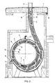
- FIG. 1 shows a view of a customer counter from the inside; 2 shows an enlarged sectional view along the line II-II of FIG. 1 and FIG. 3 shows a further enlarged view according to FIG. 2 in section through the armored box for the roller shutter shaft.
- the clear width a is usually standardized with 500 or 600 mm. Tempered glass fields are arranged to the left and right of the clear width of the customer counter, the height of the pass-through of the customer counter in such switches being approximately 1260 mm. The height is designated by b in FIG. 1 and it is clearly visible that the height b is greater than the desk height c of the customer counter measured from the ground.
- an armored box 2 is arranged below the desk surface 1, in which a roller shutter shaft 3 is rotatably mounted.
- a motor schematically indicated by 4, is connected to the roller shutter shaft 3 with an acceleration and deceleration gear.
- the roller shutter shaft 3 carries the rolled roller shutter curtain, which consists of individual double-walled profiles 5.
- the individual profiles 5 are connected to one another in an articulated manner and guided laterally in guides 6 in the area of the clear width of the customer counter.
- a flexible tension member 18 is also guided over a deflection roller 19 arranged above the upper end position of the extended roller shutter curtain, one end of the cable pull 18 being fastened to the upper edge of the first lamella 5, as indicated at 20, while the other end of the cable 18 is connected to a drive in a manner not shown.
- This drive can be directly coupled to the roller shutter shaft 3, so that when the shaft 3 rotates, the cable pull 18 is rolled up and thus supports the upward movement of the roller shutter curtain when the shaft is in a tensioned position, and jamming or jamming of the slats 5 in the guides 6 is prevented.
- a limit switch 21 is indicated, which can be formed, for example, by a spindle coupled to a pressure switch, as a result of which the drive is switched off after the height of the switch corresponding rotary movement of the roller shutter shaft 3 and the braking device acting on the shaft 3 and the spring balancer are activated.
- a cover plate is arranged above the uppermost profile 5 of the roller shutter curtain, which forms the surface 1 of the switch panel. The more precise construction is illustrated in Fig.3.
- the roller shutter shaft is again designated 3 and designed as a tubular component.
- the individual roller shutter profiles 5 are wound on the circumference of the roller shutter shaft 3, the roller shutter profiles 5 each consisting of two wall parts 7 and 8, in the cavity of which steel wool 9 is introduced as filler material.
- the individual profiles 5 are connected to one another in an articulated manner via end regions 10 which are bent out of the plane of the profiles 5, and the inner end of the roller shutter curtain formed by a plurality of such profiles 5 is connected at 11 to the outer surface of the roller shutter shaft 3, for example by welding.
- the roller shutter shaft 3 is accommodated in an armored housing 2, this housing 2 has a removable housing cover 12, which facilitates maintenance work.
- the removable cover 12 is screwed at 13 and 14 to the lower part of the armored case and thus releasably connected.
- the inner wall of the removable cover 12 and the lower part of the armored case 2 is designed as a guide surface which, when the roller shutter shaft 3 rotates, guides the profiles flung outwards in their desired position up to a slot 15, from which the roller shutter armor in the direction of the arrow 16 can be moved upwards.
- the cover-like desk 1 can be pivoted about a pivot axis 17, this pivoting taking place very quickly at high initial acceleration, so that the profiles or lamellae are rapidly moved upwards in the guides 6 in the pass-through area of the switch.
- the overall height of the armored box can be kept relatively low even with a high clear height of the customer counter opening, so that the subsequent conversion of existing switches is easily possible.
- the armor elements are bulletproof and simple profiles can be provided for the lateral guidance 6 of the roller shutter curtain in the area of the switch opening.
- the drive can be formed by an electric motor and an acceleration and deceleration gear or a torque converter gear can be flanged directly to this electric motor without the interposition of further gear elements.
- DC motors can be used to advantage.
Landscapes
- Operating, Guiding And Securing Of Roll- Type Closing Members (AREA)
- Tents Or Canopies (AREA)
- Push-Button Switches (AREA)
- Switch Cases, Indication, And Locking (AREA)
Claims (8)
Applications Claiming Priority (2)
| Application Number | Priority Date | Filing Date | Title |
|---|---|---|---|
| AT57587 | 1987-03-11 | ||
| AT575/87 | 1987-03-11 |
Publications (2)
| Publication Number | Publication Date |
|---|---|
| EP0283466A1 EP0283466A1 (fr) | 1988-09-21 |
| EP0283466B1 true EP0283466B1 (fr) | 1992-06-17 |
Family
ID=3494216
Family Applications (1)
| Application Number | Title | Priority Date | Filing Date |
|---|---|---|---|
| EP88890050A Expired - Lifetime EP0283466B1 (fr) | 1987-03-11 | 1988-03-10 | Dispositif de protection pour guichets |
Country Status (3)
| Country | Link |
|---|---|
| EP (1) | EP0283466B1 (fr) |
| AT (1) | ATE77434T1 (fr) |
| DE (1) | DE3872008D1 (fr) |
Families Citing this family (4)
| Publication number | Priority date | Publication date | Assignee | Title |
|---|---|---|---|---|
| AU624505B2 (en) * | 1990-01-22 | 1992-06-11 | Sanwa Shutter Corporation | Shutter assembly for a bay window |
| GB9112683D0 (en) * | 1991-06-13 | 1991-07-31 | Tidmarsh Estate Ltd | Screen |
| ATE152802T1 (de) * | 1993-06-30 | 1997-05-15 | Olaf Clausen | Sicherheits-schaltertheke |
| GB2316118B (en) * | 1996-08-05 | 2001-02-21 | Alan Paul Young | Upwardly closing window shutter |
Citations (1)
| Publication number | Priority date | Publication date | Assignee | Title |
|---|---|---|---|---|
| EP0044880A1 (fr) * | 1980-07-30 | 1982-02-03 | Türenwerke Riexinger GmbH & Co.KG | Lame pour porte enroulable ou porte à lames articulées; installation et procédé pour la fabrication d'une telle lame |
Family Cites Families (6)
| Publication number | Priority date | Publication date | Assignee | Title |
|---|---|---|---|---|
| US1681481A (en) * | 1926-04-13 | 1928-08-21 | John W Johnston | Bank-protecting device |
| GB400953A (en) * | 1932-04-25 | 1933-10-25 | Reginald William Tate | Apparatus for the protection of the contents of shop windows and the like and cashiers in banks and the like from theft or attack |
| FR2242735B1 (fr) * | 1973-09-18 | 1977-07-29 | Morel Jacques | |
| FR2439288A1 (fr) * | 1978-10-17 | 1980-05-16 | Engelart Ets | Guichet de securite |
| FR2476731A1 (fr) * | 1980-02-27 | 1981-08-28 | Jacques Morel | Dispositif de protection contre les agressions |
| EP0083550A3 (fr) * | 1981-10-26 | 1983-08-17 | Christina Weibel-Staub | Elément à installer dans une ouverture de fenêtre ou de porte d'un bâtiment |
-
1988
- 1988-03-10 DE DE8888890050T patent/DE3872008D1/de not_active Expired - Fee Related
- 1988-03-10 AT AT88890050T patent/ATE77434T1/de not_active IP Right Cessation
- 1988-03-10 EP EP88890050A patent/EP0283466B1/fr not_active Expired - Lifetime
Patent Citations (1)
| Publication number | Priority date | Publication date | Assignee | Title |
|---|---|---|---|---|
| EP0044880A1 (fr) * | 1980-07-30 | 1982-02-03 | Türenwerke Riexinger GmbH & Co.KG | Lame pour porte enroulable ou porte à lames articulées; installation et procédé pour la fabrication d'une telle lame |
Also Published As
| Publication number | Publication date |
|---|---|
| ATE77434T1 (de) | 1992-07-15 |
| DE3872008D1 (de) | 1992-07-23 |
| EP0283466A1 (fr) | 1988-09-21 |
Similar Documents
| Publication | Publication Date | Title |
|---|---|---|
| EP0701649B1 (fr) | Leve-vitre manuel a cable | |
| DE19713458B4 (de) | Tor mit einer Zugseileinrichtung | |
| EP1197627B1 (fr) | Commande pour portes, en particulier portes de garages | |
| DE19610268A1 (de) | Rolloeinrichtung für ein Isolierglaselement | |
| EP0283466B1 (fr) | Dispositif de protection pour guichets | |
| DE3508175A1 (de) | Garagentor oder hallentor mit feder-hubmechanik | |
| EP0109382A2 (fr) | Vitrage isolant | |
| DE19819558A1 (de) | Automatische Türanlage | |
| DE29903517U1 (de) | Tor | |
| EP1524400B1 (fr) | Dispositif de volet roulant avec une ouverture horizontale variable en forme d'échancrure | |
| EP3464766B1 (fr) | Système pliant relevable avec dispositif de verrouillage et dispositif d'entraînement | |
| DE19860765A1 (de) | Gehäuse, insbesondere für eine Verpackungsmaschine | |
| EP0945575B1 (fr) | Porte sectionnelle relevable | |
| DE3515404C2 (fr) | ||
| DE29609604U1 (de) | Behang zur Abdunkelung von Fensteröffnungen | |
| EP1707726B1 (fr) | Dispositif pour l'ouverture et la fermeture d'une fenêtre ou porte montée coulissante sur un cadre | |
| DE3146606C2 (de) | Doppelkassenschalter | |
| EP0724064B1 (fr) | Système de volet roulant | |
| DE29903543U1 (de) | Hub-(Sektional-)tor | |
| WO1988007618A1 (fr) | Porte, notamment porte motorisee a usage industriel | |
| DE19601897B4 (de) | Aufhänge-Vorrichtung für einen Lamellen-Vorhang | |
| EP1031700B1 (fr) | Volet roulant pour fenêtres ou portes | |
| DE3424600A1 (de) | Rolltor | |
| EP1099037A2 (fr) | Porte basculante ou sectionnee a actionnement motorise ou manuel | |
| DE10047372C1 (de) | Antrieb für Tore, insbesondere Garagentore |
Legal Events
| Date | Code | Title | Description |
|---|---|---|---|
| PUAI | Public reference made under article 153(3) epc to a published international application that has entered the european phase |
Free format text: ORIGINAL CODE: 0009012 |
|
| AK | Designated contracting states |
Kind code of ref document: A1 Designated state(s): AT CH DE FR IT LI |
|
| 17P | Request for examination filed |
Effective date: 19890224 |
|
| 17Q | First examination report despatched |
Effective date: 19900720 |
|
| GRAA | (expected) grant |
Free format text: ORIGINAL CODE: 0009210 |
|
| AK | Designated contracting states |
Kind code of ref document: B1 Designated state(s): AT CH DE FR IT LI |
|
| REF | Corresponds to: |
Ref document number: 77434 Country of ref document: AT Date of ref document: 19920715 Kind code of ref document: T |
|
| REF | Corresponds to: |
Ref document number: 3872008 Country of ref document: DE Date of ref document: 19920723 |
|
| ITF | It: translation for a ep patent filed | ||
| ET | Fr: translation filed | ||
| PGFP | Annual fee paid to national office [announced via postgrant information from national office to epo] |
Ref country code: FR Payment date: 19930317 Year of fee payment: 6 |
|
| PGFP | Annual fee paid to national office [announced via postgrant information from national office to epo] |
Ref country code: DE Payment date: 19930327 Year of fee payment: 6 |
|
| PGFP | Annual fee paid to national office [announced via postgrant information from national office to epo] |
Ref country code: AT Payment date: 19930329 Year of fee payment: 6 |
|
| ITTA | It: last paid annual fee | ||
| PLBE | No opposition filed within time limit |
Free format text: ORIGINAL CODE: 0009261 |
|
| STAA | Information on the status of an ep patent application or granted ep patent |
Free format text: STATUS: NO OPPOSITION FILED WITHIN TIME LIMIT |
|
| 26N | No opposition filed | ||
| PG25 | Lapsed in a contracting state [announced via postgrant information from national office to epo] |
Ref country code: AT Effective date: 19940310 |
|
| PGFP | Annual fee paid to national office [announced via postgrant information from national office to epo] |
Ref country code: CH Payment date: 19940317 Year of fee payment: 7 |
|
| PG25 | Lapsed in a contracting state [announced via postgrant information from national office to epo] |
Ref country code: FR Effective date: 19941130 |
|
| PG25 | Lapsed in a contracting state [announced via postgrant information from national office to epo] |
Ref country code: DE Effective date: 19941201 |
|
| REG | Reference to a national code |
Ref country code: FR Ref legal event code: ST |
|
| PG25 | Lapsed in a contracting state [announced via postgrant information from national office to epo] |
Ref country code: LI Effective date: 19950331 Ref country code: CH Effective date: 19950331 |
|
| REG | Reference to a national code |
Ref country code: CH Ref legal event code: PL |
|
| PG25 | Lapsed in a contracting state [announced via postgrant information from national office to epo] |
Ref country code: IT Free format text: LAPSE BECAUSE OF NON-PAYMENT OF DUE FEES Effective date: 20050310 |