EP0283502B1 - Chaine de transmission de prise de force - Google Patents
Chaine de transmission de prise de force Download PDFInfo
- Publication number
- EP0283502B1 EP0283502B1 EP19870906405 EP87906405A EP0283502B1 EP 0283502 B1 EP0283502 B1 EP 0283502B1 EP 19870906405 EP19870906405 EP 19870906405 EP 87906405 A EP87906405 A EP 87906405A EP 0283502 B1 EP0283502 B1 EP 0283502B1
- Authority
- EP
- European Patent Office
- Prior art keywords
- clutch
- drive
- drive line
- bearing
- driven shaft
- Prior art date
- Legal status (The legal status is an assumption and is not a legal conclusion. Google has not performed a legal analysis and makes no representation as to the accuracy of the status listed.)
- Expired - Lifetime
Links
Images

Classifications
-
- F—MECHANICAL ENGINEERING; LIGHTING; HEATING; WEAPONS; BLASTING
- F16—ENGINEERING ELEMENTS AND UNITS; GENERAL MEASURES FOR PRODUCING AND MAINTAINING EFFECTIVE FUNCTIONING OF MACHINES OR INSTALLATIONS; THERMAL INSULATION IN GENERAL
- F16C—SHAFTS; FLEXIBLE SHAFTS; ELEMENTS OR CRANKSHAFT MECHANISMS; ROTARY BODIES OTHER THAN GEARING ELEMENTS; BEARINGS
- F16C41/00—Other accessories, e.g. devices integrated in the bearing not relating to the bearing function as such
- F16C41/001—Integrated brakes or clutches for stopping or coupling the relatively movable parts
-
- B—PERFORMING OPERATIONS; TRANSPORTING
- B60—VEHICLES IN GENERAL
- B60K—ARRANGEMENT OR MOUNTING OF PROPULSION UNITS OR OF TRANSMISSIONS IN VEHICLES; ARRANGEMENT OR MOUNTING OF PLURAL DIVERSE PRIME-MOVERS IN VEHICLES; AUXILIARY DRIVES FOR VEHICLES; INSTRUMENTATION OR DASHBOARDS FOR VEHICLES; ARRANGEMENTS IN CONNECTION WITH COOLING, AIR INTAKE, GAS EXHAUST OR FUEL SUPPLY OF PROPULSION UNITS IN VEHICLES
- B60K17/00—Arrangement or mounting of transmissions in vehicles
- B60K17/28—Arrangement or mounting of transmissions in vehicles characterised by arrangement, location, or type of power take-off
-
- F—MECHANICAL ENGINEERING; LIGHTING; HEATING; WEAPONS; BLASTING
- F16—ENGINEERING ELEMENTS AND UNITS; GENERAL MEASURES FOR PRODUCING AND MAINTAINING EFFECTIVE FUNCTIONING OF MACHINES OR INSTALLATIONS; THERMAL INSULATION IN GENERAL
- F16C—SHAFTS; FLEXIBLE SHAFTS; ELEMENTS OR CRANKSHAFT MECHANISMS; ROTARY BODIES OTHER THAN GEARING ELEMENTS; BEARINGS
- F16C25/00—Bearings for exclusively rotary movement adjustable for wear or play
- F16C25/06—Ball or roller bearings
- F16C25/08—Ball or roller bearings self-adjusting
-
- F—MECHANICAL ENGINEERING; LIGHTING; HEATING; WEAPONS; BLASTING
- F16—ENGINEERING ELEMENTS AND UNITS; GENERAL MEASURES FOR PRODUCING AND MAINTAINING EFFECTIVE FUNCTIONING OF MACHINES OR INSTALLATIONS; THERMAL INSULATION IN GENERAL
- F16D—COUPLINGS FOR TRANSMITTING ROTATION; CLUTCHES; BRAKES
- F16D67/00—Combinations of couplings and brakes; Combinations of clutches and brakes
- F16D67/02—Clutch-brake combinations
- F16D67/04—Clutch-brake combinations fluid actuated
Definitions
- This invention relates to power take-off (PTO) drive lines used on agricultural or industrial tractors to drive implements such as spinner broadcasters, mowers, balers etc. of the type disclosed in patent documents FR-A-2311675, GB-A-984325 and GB-A-2154694.
- PTO power take-off
- PTO drive lines conventionally include a clutch which allows drive to the implement to be disconnected.
- the clutch is disengaged drag within the clutch may continue to result in unwanted rotation of the drive line output shaft.
- this unwanted output shaft rotation due to clutch drag is of particular concern when the PTO clutch is oil cooled and thus has more internal drag.
- the PTO drive line may for example, pass down the centre of a tractor transmission drive shaft and drag may occur between the concentric shafts again resulting in unwanted rotation of the PTO drive line output shaft.
- a power take-off drive line including a drive shaft, a driven shaft, with which an implement may be connected, a disengageable power take-off clutch for connecting and disconnecting drive between the drive and driven shafts, bearing means for supporting the driven shaft for rotation, and brake means to inhibit any tendency of the driven shaft to rotate when the clutch is disengaged due to drag in the clutch or elsewhere in the drive line, said drive line being characterised in that said brake means includes an actuator which acts on the bearing means to increase the frictional resistance of the bearing means to provide the braking effect and in that actuation means is provided to enable an operator to apply the desired effect when required.
- the rotation of the driven shaft is inhibited thus mitigating the problem of unwanted drive shaft rotation.
- the drive line is powering a low inertia implement such as a spinner broadcaster, unwanted rotation of the output shaft would result in unwanted distribution of the material being spread by the broadcaster.
- the brake means of the present invention is not intended to arrest any high inertia implement which may be connected to the driven shaft.
- the bearing means includes a roller bearing with rollers disposed between inner and outer cages and the actuator axially displaces one of the cages to increase the bearing friction to provide the desired braking effect.
- the actuator includes a fluid pressure operated piston for displacement of the cage.
- the drive line clutch and actuation means may conveniently be controlled by a single actuation means having three positions, a first position in which the clutch is engaged, and the brake is disengaged, a second position in which the brake means is engaged and the clutch is disengaged and a third position in which both the clutch and brake means are disengaged.
- the clutch and actuator means may both be fluid pressure operated, for example using solenoid operated fluid flow control valves.
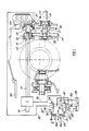
- the PTO drive line is disposed in a back axle housing 30 and comprises a drive shaft 10 driven directly from the tractor engine (not shown) and a driven shaft 11 which can be driven from the shaft 10 via an hydraulically engaged PTO clutch C which is oil-cooled.
- the supply of oil coolant to the clutch is controlled in the known manner so that coolant flow is disconnected when the clutch is disengaged. Since the constructional details of clutch C and its associated coolant system form no part of the present invention (and suitable forms will be well known to persons skilled in the art), no further details of the clutch C will be given in the present application.
- Gear wheels 12 and 13 which are formed as a single casting which is splined onto the end of shaft 11 at 14.
- the rearward end of shaft 11 is supported from housing 30 via angled roller bearings 15 and 16.
- Gear wheels 12 and 13 mesh with gears 17 and 18 respectively.
- Gear 17 may be engaged via spline 20 with a PTO output shaft 19 (half of which is shown in Figure 1) while alternatively gear 18 may be engaged via spline 21 with an alternative PTO output shaft 22 (half of which is shown in Figure 1).
- a braking means is provided for shaft 11 to prevent rotation of this shaft when clutch C is disengaged.
- This braking arrangement is best seen in Figure 2 and comprises a piston 23 with a lip 24 which bears against the outer cage 16′ of bearing 16. Piston 23 is displaceable in a blind bore 25 by admitting pressurised fluid into chamber 26 via connection 27 in housing 30.
- a lubrication passageway 28 is also provided in housing 30 which communicates a flow of lubricating oil to an annular groove 40 cut in blind bore 25.
- Piston lip 24 is proved with a series of drillings 29 through which the lubricating oil can lubricate bearing 16 (as shown by arrows X) or can travel down the centre of gearwheels 12 and 13 (as shown by arrows Y) to lubricate other bearings not shown.
- Figure 1 shows one form of hydraulic circuit for operating clutch C and displacing the braking piston 23.
- This comprises a pivoting lever 31 which can be moved between three positions 31C, 31N, 31B to control two solenoid operated hydraulic valves 32 and 33 which receive pressured fluid from a pump 34 and direct this fluid to the brake piston 23 and clutch C via lines 35 and 36 respectively.
- the lever 31 when in positions 31B and 31C operates switches 32′ and 33′ respectively, which in turn energise solenoids 32 ⁇ and 33 ⁇ associated with valves 32 and 33.
- switch 33′ is operated to energise solenoid 33 ⁇ and hence displace valve 33 against spring loading 40 to pressurise the actuator of clutch C via line 36 and thus engage clutch C.
- switch 32′ is operated to energise solenoid 32 ⁇ and hence displace valve 32 against spring loading 39 to pressurise chamber 26 and hence move piston 23 to the left, as viewed in Figure 2, thus increasing the end loading on the outer cage 16′ of bearing 16 and hence generating sufficient friction within bearing 16 to overcome any drag in clutch C and prevent rotation of shaft 11 when clutch C disengaged.
- the present invention thus provides a simple arrangement for overcoming the above described problem of PTO shaft rotation due to unwanted drag whether this drag occurs in the clutch or in a concentric drive shaft arrangement as referred to above.
Landscapes
- Engineering & Computer Science (AREA)
- General Engineering & Computer Science (AREA)
- Mechanical Engineering (AREA)
- Chemical & Material Sciences (AREA)
- Combustion & Propulsion (AREA)
- Transportation (AREA)
- Arrangement And Driving Of Transmission Devices (AREA)
- Braking Arrangements (AREA)
Abstract
Claims (5)
Applications Claiming Priority (2)
| Application Number | Priority Date | Filing Date | Title |
|---|---|---|---|
| GB8622844A GB8622844D0 (en) | 1986-09-23 | 1986-09-23 | Power take-off drive lines |
| GB8622844 | 1986-09-23 |
Publications (2)
| Publication Number | Publication Date |
|---|---|
| EP0283502A1 EP0283502A1 (fr) | 1988-09-28 |
| EP0283502B1 true EP0283502B1 (fr) | 1991-04-03 |
Family
ID=10604630
Family Applications (1)
| Application Number | Title | Priority Date | Filing Date |
|---|---|---|---|
| EP19870906405 Expired - Lifetime EP0283502B1 (fr) | 1986-09-23 | 1987-09-15 | Chaine de transmission de prise de force |
Country Status (5)
| Country | Link |
|---|---|
| EP (1) | EP0283502B1 (fr) |
| JP (1) | JP2556983B2 (fr) |
| BR (1) | BR8707467A (fr) |
| GB (1) | GB8622844D0 (fr) |
| WO (1) | WO1988002320A1 (fr) |
Families Citing this family (4)
| Publication number | Priority date | Publication date | Assignee | Title |
|---|---|---|---|---|
| EP0692645B1 (fr) * | 1994-07-15 | 2002-11-13 | Volkswagen Aktiengesellschaft | Palier d'un arbre de transmission |
| DE19515045C1 (de) * | 1995-04-24 | 1995-11-30 | Traub Ag | Werkstück-Spindelanordnung, insbesondere zum Abgreifen eines Werkstücks an einer Drehmaschine |
| CN102016367A (zh) | 2008-07-07 | 2011-04-13 | 伊格尔工业股份有限公司 | 机械密封装置 |
| SE538560C2 (en) * | 2014-12-10 | 2016-09-20 | Scania Cv Ab | A gearbox with a PTO clutch with integrated shaft brake |
Family Cites Families (3)
| Publication number | Priority date | Publication date | Assignee | Title |
|---|---|---|---|---|
| US3209872A (en) * | 1962-04-19 | 1965-10-05 | Int Harvester Co | Independent power take-off with clutch and anti-creep brake |
| DE2522411C3 (de) * | 1975-05-21 | 1978-04-13 | Kloeckner-Humboldt-Deutz Ag, 5000 Koeln | Nebenantrieb, insbesondere Zapfwellenantrieb eines Zahnräderwechselgetriebes für land- und/oder bauwirtschaftlich nutzbare Kraftfahrzeuge |
| GB2154694B (en) * | 1984-02-20 | 1987-07-08 | Kanzaki Kokyukoki Mfg Co Ltd | Clutch brake combination in a power transmission for motor vehicles |
-
1986
- 1986-09-23 GB GB8622844A patent/GB8622844D0/en active Pending
-
1987
- 1987-09-15 WO PCT/EP1987/000521 patent/WO1988002320A1/fr not_active Ceased
- 1987-09-15 BR BR8707467A patent/BR8707467A/pt not_active IP Right Cessation
- 1987-09-15 EP EP19870906405 patent/EP0283502B1/fr not_active Expired - Lifetime
- 1987-09-15 JP JP62505945A patent/JP2556983B2/ja not_active Expired - Fee Related
Also Published As
| Publication number | Publication date |
|---|---|
| JP2556983B2 (ja) | 1996-11-27 |
| GB8622844D0 (en) | 1986-10-29 |
| BR8707467A (pt) | 1988-09-13 |
| JPH01501134A (ja) | 1989-04-20 |
| WO1988002320A1 (fr) | 1988-04-07 |
| EP0283502A1 (fr) | 1988-09-28 |
Similar Documents
| Publication | Publication Date | Title |
|---|---|---|
| EP0925201B1 (fr) | Dispositif d'entrainement de roue hydrostatique et mecanique | |
| US4205739A (en) | Metering device for steering brake lube systems | |
| DE60301762T2 (de) | Elektronische, gesteuerte Kupplung | |
| EP0262862B1 (fr) | Transmission de prise de force | |
| EP0150890A2 (fr) | Transmission pour véhicule à moteur comprenant un dispositif anti-recul | |
| DE3506346C2 (de) | Getriebe für Kraftfahrzeuge | |
| US4905812A (en) | Apparatus for cooling a clutch assembly with a hydraulic fluid | |
| DE68906116T2 (de) | Regelsystem fuer ein wahlweise zwei- oder vierradangetriebenes kraftfahrzeug mit einem stufenlos regelbaren umschlingungsgetriebe. | |
| DE112016000913B4 (de) | Pumpenloses Verteilergetriebe für Trennachsen | |
| US3507372A (en) | Hydraulic clutch and brake system | |
| DE10249660A1 (de) | Leistungsübertragungssystem mit Nebengetriebemechanismus | |
| US11193561B2 (en) | Drive assembly with lubricant reservoir | |
| NZ195159A (en) | Two speed transmission for tractor:hydraulic clutches select direct drive or drive via reduction gears | |
| EP0283502B1 (fr) | Chaine de transmission de prise de force | |
| DE102022202293A1 (de) | Hydraulikkupplungsanordnung mit doppelt wirkendem kolben | |
| EP0952027B1 (fr) | Prise de force pour véhicule agricole et procédé de mise en oeuvre associé | |
| EP0952367B1 (fr) | Système de commande hydraulique pour l'embrayage dans une prise de force | |
| DE1530771B2 (de) | Vorrichtung zum Steuern des Ein- und Ausrückens einer hydraulisch betätigten Kupplung eines Kraftfahrzeuges | |
| US5195933A (en) | Friction drive transmission | |
| CA1076970A (fr) | Graisseur-doseur pour freins de direction | |
| DE102017202693B3 (de) | Getriebe mit unterbrechungsfreier Schmierung | |
| CA1278690C (fr) | Embrayage commande par fluide a verrouillage reciproque de surete du raccord collecteur de fluide | |
| KR102907691B1 (ko) | 농업용 작업차량의 변속기용 유압장치 | |
| JP2019157999A (ja) | 作業車両 | |
| JPS5925694Y2 (ja) | 農用トラクタのpto装置潤滑機構 |
Legal Events
| Date | Code | Title | Description |
|---|---|---|---|
| PUAI | Public reference made under article 153(3) epc to a published international application that has entered the european phase |
Free format text: ORIGINAL CODE: 0009012 |
|
| 17P | Request for examination filed |
Effective date: 19880609 |
|
| AK | Designated contracting states |
Kind code of ref document: A1 Designated state(s): DE FR GB IT SE |
|
| 17Q | First examination report despatched |
Effective date: 19900205 |
|
| GRAA | (expected) grant |
Free format text: ORIGINAL CODE: 0009210 |
|
| AK | Designated contracting states |
Kind code of ref document: B1 Designated state(s): DE FR GB IT SE |
|
| PG25 | Lapsed in a contracting state [announced via postgrant information from national office to epo] |
Ref country code: SE Effective date: 19910403 |
|
| ITF | It: translation for a ep patent filed | ||
| REF | Corresponds to: |
Ref document number: 3769129 Country of ref document: DE Date of ref document: 19910508 |
|
| ET | Fr: translation filed | ||
| PLBE | No opposition filed within time limit |
Free format text: ORIGINAL CODE: 0009261 |
|
| STAA | Information on the status of an ep patent application or granted ep patent |
Free format text: STATUS: NO OPPOSITION FILED WITHIN TIME LIMIT |
|
| 26N | No opposition filed | ||
| REG | Reference to a national code |
Ref country code: GB Ref legal event code: 732E |
|
| REG | Reference to a national code |
Ref country code: FR Ref legal event code: GC |
|
| REG | Reference to a national code |
Ref country code: FR Ref legal event code: CL |
|
| REG | Reference to a national code |
Ref country code: FR Ref legal event code: CD Ref country code: FR Ref legal event code: TP |
|
| REG | Reference to a national code |
Ref country code: GB Ref legal event code: IF02 |
|
| PGFP | Annual fee paid to national office [announced via postgrant information from national office to epo] |
Ref country code: DE Payment date: 20040818 Year of fee payment: 18 |
|
| PG25 | Lapsed in a contracting state [announced via postgrant information from national office to epo] |
Ref country code: DE Free format text: LAPSE BECAUSE OF NON-PAYMENT OF DUE FEES Effective date: 20060401 |
|
| PGFP | Annual fee paid to national office [announced via postgrant information from national office to epo] |
Ref country code: FR Payment date: 20060810 Year of fee payment: 20 |
|
| PGFP | Annual fee paid to national office [announced via postgrant information from national office to epo] |
Ref country code: GB Payment date: 20060811 Year of fee payment: 20 |
|
| PGFP | Annual fee paid to national office [announced via postgrant information from national office to epo] |
Ref country code: IT Payment date: 20060930 Year of fee payment: 20 |
|
| REG | Reference to a national code |
Ref country code: GB Ref legal event code: PE20 |
|
| PG25 | Lapsed in a contracting state [announced via postgrant information from national office to epo] |
Ref country code: GB Free format text: LAPSE BECAUSE OF EXPIRATION OF PROTECTION Effective date: 20070914 |