EP0283578A2 - Flugzeug, vorzugsweise Hubschrauber - Google Patents
Flugzeug, vorzugsweise Hubschrauber Download PDFInfo
- Publication number
- EP0283578A2 EP0283578A2 EP87118478A EP87118478A EP0283578A2 EP 0283578 A2 EP0283578 A2 EP 0283578A2 EP 87118478 A EP87118478 A EP 87118478A EP 87118478 A EP87118478 A EP 87118478A EP 0283578 A2 EP0283578 A2 EP 0283578A2
- Authority
- EP
- European Patent Office
- Prior art keywords
- combustion engine
- internal combustion
- cabin
- air
- air inlet
- Prior art date
- Legal status (The legal status is an assumption and is not a legal conclusion. Google has not performed a legal analysis and makes no representation as to the accuracy of the status listed.)
- Ceased
Links
Images

Classifications
-
- B—PERFORMING OPERATIONS; TRANSPORTING
- B64—AIRCRAFT; AVIATION; COSMONAUTICS
- B64D—EQUIPMENT FOR FITTING IN OR TO AIRCRAFT; FLIGHT SUITS; PARACHUTES; ARRANGEMENT OR MOUNTING OF POWER PLANTS OR PROPULSION TRANSMISSIONS IN AIRCRAFT
- B64D33/00—Arrangement in aircraft of power plant parts or auxiliaries not otherwise provided for
- B64D33/08—Arrangement in aircraft of power plant parts or auxiliaries not otherwise provided for of power plant cooling systems
-
- F—MECHANICAL ENGINEERING; LIGHTING; HEATING; WEAPONS; BLASTING
- F01—MACHINES OR ENGINES IN GENERAL; ENGINE PLANTS IN GENERAL; STEAM ENGINES
- F01P—COOLING OF MACHINES OR ENGINES IN GENERAL; COOLING OF INTERNAL-COMBUSTION ENGINES
- F01P11/00—Component parts, details, or accessories not provided for in, or of interest apart from, groups F01P1/00 - F01P9/00
- F01P11/10—Guiding or ducting cooling-air, to, or from, liquid-to-air heat exchangers
-
- F—MECHANICAL ENGINEERING; LIGHTING; HEATING; WEAPONS; BLASTING
- F01—MACHINES OR ENGINES IN GENERAL; ENGINE PLANTS IN GENERAL; STEAM ENGINES
- F01P—COOLING OF MACHINES OR ENGINES IN GENERAL; COOLING OF INTERNAL-COMBUSTION ENGINES
- F01P5/00—Pumping cooling-air or liquid coolants
- F01P5/02—Pumping cooling-air; Arrangements of cooling-air pumps, e.g. fans or blowers
- F01P5/06—Guiding or ducting air to, or from, ducted fans
-
- F—MECHANICAL ENGINEERING; LIGHTING; HEATING; WEAPONS; BLASTING
- F02—COMBUSTION ENGINES; HOT-GAS OR COMBUSTION-PRODUCT ENGINE PLANTS
- F02B—INTERNAL-COMBUSTION PISTON ENGINES; COMBUSTION ENGINES IN GENERAL
- F02B61/00—Adaptations of engines for driving vehicles or for driving propellers; Combinations of engines with gearing
- F02B61/06—Combinations of engines with mechanical gearing
-
- F—MECHANICAL ENGINEERING; LIGHTING; HEATING; WEAPONS; BLASTING
- F02—COMBUSTION ENGINES; HOT-GAS OR COMBUSTION-PRODUCT ENGINE PLANTS
- F02B—INTERNAL-COMBUSTION PISTON ENGINES; COMBUSTION ENGINES IN GENERAL
- F02B75/00—Other engines
- F02B75/16—Engines characterised by number of cylinders, e.g. single-cylinder engines
- F02B75/18—Multi-cylinder engines
- F02B75/24—Multi-cylinder engines with cylinders arranged oppositely relative to main shaft and of "flat" type
- F02B75/243—Multi-cylinder engines with cylinders arranged oppositely relative to main shaft and of "flat" type with only one crankshaft of the "boxer" type, e.g. all connecting rods attached to separate crankshaft bearings
Definitions
- the invention relates to an aircraft, preferably a helicopter, according to the preamble of patent claim 1.
- GB-PS 732 452 a vertical boxer internal combustion engine is shown which drives a rotor of an aircraft.
- the object of the invention is to make such arrangements and precautions on a helicopter driven by an internal combustion engine that the internal combustion engine and its units are reliably supplied with cooling air even under extreme operating conditions while ensuring a good intake air supply.
- the main advantages achieved with the invention are the fact that the cooling air blower and the suction system of the internal combustion engine are supplied in a simple and advantageous manner with the respective medium - cooling air, intake air -, the existing pressure drop between the side wall and underside of the cabin being effective for disposal the used cooling air is used.
- the air intake openings on the long sides of the cabin, through which sufficient air enters, can be easily integrated into the side walls of the helicopter.
- the guide channels, the pipe system and the outlet channel are easily manufactured parts and can be easily installed within the cabin.
- the coolers - oil coolers and / or charge air coolers - are flowed through by functional cooling air.
- the coolers are sufficiently supplied with cooling air.
- a helicopter 1 comprises a cabin 2 which is carried by runners 3. 4 denotes a rotor which is connected to an internal combustion engine 6 via a shaft 5 and by means of a clutch system (not shown).
- the cabin 2 has a windscreen 7 and side doors 8 which delimit a passenger compartment 9.
- the passenger compartment 9 is separated from an aggregate compartment 11 by means of a transverse wall 10.
- the cabin has 2 side walls 12, 13, which have the greatest distance from one another approximately in the region of the transverse wall 10.
- the piston-type internal combustion engine 6 is air-cooled, its six cylinders 14 being arranged in two rows 15, 16 in a common plane, in such a way that the internal combustion engine has a boxer shape.
- the internal combustion engine 6 is arranged lying in a central longitudinal plane A-A of the helicopter 1, i.e. the cylinder rows 15, 16 run approximately in a horizontal plane.
- the internal combustion engine 6 is equipped on its front side 17 - seen in the direction of flight B - with a cooling fan 18 which is driven by its crankshaft with the interposition of a gearbox. The latter is not shown.
- inlet openings 19, 20 are provided on the side walls 12, 13, which are equipped with grilles 21, 22.
- the grids 21, 22 are with slats 23 provided, the shape of which largely prevents dirt particles from entering the air inlet openings (FIG. 3).
- Guide channels 24, 25, which are brought together at 26, extend between the air inlet openings 19, 20 and the cooling air blower 18.
- the heated cooling medium leaving the internal combustion engine 6 emerges from it at about 27 and leaves the cabin 2 through an outlet opening 28 on the underside 29 of the said cabin 2. This results in an existing pressure drop between the side walls 12, 13 and the underside 29 for supply and Disposal of the cooling air used.
- the intake air can be guided via a pipe system 30 to an intake port of the internal combustion engine 6, which is not shown in detail.
- the internal combustion engine 6 is supplied with this medium by the ambient air in the unit space 11, which is connected to the outside of the cabin 2 via the air inlet openings 19, 20.
- guide channels 31, 32 are guided, which extend in the direction of the rear of the helicopter 1. Coolers 33, 34 are inserted into the guide channels 31, 32, the cooler 33 being a charge air cooler and the cooler 34 being an oil cooler.
- the guide channels 31, 32 are connected in a fork-like manner to an outlet channel 35, which extends in the central longitudinal plane B-B and whose outlet opening 36 is also attached to the underside 29 of the cabin 2.
- the outlet opening 36 and the outlet opening 28 are provided at different locations in the cabin.
- an additional fan 37 is arranged in the outlet duct 35, which is connected downstream of the coolers 34, 35.
- the additional fan 37 is driven by the crankshaft of the internal combustion engine 6.
Landscapes
- Engineering & Computer Science (AREA)
- Chemical & Material Sciences (AREA)
- Combustion & Propulsion (AREA)
- Mechanical Engineering (AREA)
- General Engineering & Computer Science (AREA)
- Aviation & Aerospace Engineering (AREA)
- Cooling, Air Intake And Gas Exhaust, And Fuel Tank Arrangements In Propulsion Units (AREA)
- Turbine Rotor Nozzle Sealing (AREA)
- Catching Or Destruction (AREA)
- Agricultural Chemicals And Associated Chemicals (AREA)
Abstract
Description
- Die Erfindung betrifft ein Flugzeug, vorzugsweise Hubschrauber, nach dem Oberbegriff des Patentanspruchs 1.
- In der GB-PS 732 452 wird eine senkrecht stehende Boxer-Brennkraftmaschine gezeigt, die einen Rotor eines Fluggerätes antreibt.
- Aus der GB-PS 588 317 geht eine Flugzeugbrennkraftmaschine, ebenfalls der Boxerbauart, hervor, deren Zylinder horizontal liegend angeordnet sind.
- Aufgabe der Erfindung ist es, an einem von einer Brennkraftmaschine angetriebenen Hubschrauber solche Anordnungen und Vorkehrungen zu treffen, daß unter Sicherstellung einer guten Ansaugluftzuführung die Brennkraftmaschine und ihre Aggregate auch unter extremen Betriebsbedingungen auf sichere Weise mit Kühlluft versorgt werden.
- Erfindungsgemäß wird diese Aufgabe durch die kennzeichnenden Merkmale des Anspruchs 1 gelöst.
- Die mit der Erfindung hauptsächlich erzielten Vorteile sind darin zu sehen, daß das Kühlluftgebläse und die Sauganlage der Brennkraftmaschine auf einfache und vorteilhafte Art mit dem jeweiligen Medium - Kühlluft, Ansaugluft - versorgt werden, wobei das vorhandene Druckgefälle zwischen Seitenwand und Unterseite der Kabine wirkungsvoll zur Entsorgung der verbrauchten Kühlluft ausgenutzt wird. Die Lufteinlaßöffnungen an den Längsseiten der Kabine, über die ausreichende Menge Luft eintritt, können problemlos in die Seitenwände des Hubschraubers integriert werden. Die Führungskanäle, die Rohranlage und der Auslaßkanal sind leicht herstellbare Teile und können ohne weiteres innerhalb der Kabine verlegt werden.
- Die Kühler - Ölkühler und/oder Ladeluftkühler - werden funktionsgerecht von Kühlluft durchströmt. Insbesondere auch wegen des von der Brennkraftmaschine angetriebenen Zusatzgebläses, das gewährleistet, daß bei extremer Flugsituation, beispielsweise Schwebeflug, die Kühler ausreichend mit Kühlluft beaufschlagt werden.
- In der Zeichnung wird ein Ausführungsbeispiel der Erfindung gezeigt, das nachstehend näher beschrieben ist.
- Es zeigt
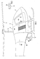
- Fig. 1 eine Teilseitenansicht eines Hubschraubers,
- Fig. 2 einen Schnitt nach der Linie II-II der Fig. 1,
- Fig. 3 eine Einzelheit X der Fig. 2 in größerem Maßstab.
- Ein Hubschrauber 1 umfasst eine Kabine 2, die von Kufen 3 getragen wird. Mit 4 ist ein Rotor bezeichnet, der über eine Welle 5 und unter Vermittlung eines nicht gezeigten Kupplungssystems mit einer Brennkraftmaschine 6 verbunden ist.
- Die Kabine 2 weist eine Frontscheibe 7 und Seitentüren 8 auf, die einen Fahrgastraum 9 begrenzen. Der Fahrgastraum 9 ist mittels einer Querwand 10 von einem Aggregateraum 11 getrennt. Außerdem besitzt die Kabine 2 Seitenwände 12, 13, die etwa im Bereich der Querwand 10 die größte Distanz zueinander haben.
- Die Brennkraftmaschine 6 der Kolbenbauart ist luftgekühlt, wobei ihre sechs Zylinder 14 in zwei Reihen 15, 16, und zwar in einer gemeinsamen Ebene , angeordnet sind, derart, daß die Brennkraftmaschine Boxerform aufweist.
- Im Ausführungsbeispiel ist die Brennkraftmaschine 6 liegend in einer Mittellängsebene A-A des Hubschraubers 1 angeordnet, d.h., die Zylinderreihen 15, 16 verlaufen etwa in einer horizontalen Ebene. Darüber hinaus ist die Brennkraftmaschine 6 an ihrer Vorderseite 17 - in Flugrichtung B gesehen - mit einem Kühlgebläse 18 ausgerüstet, das unter Zwischenschaltung eines Getriebes von ihrer Kurbelwelle angetrieben wird. Letzteres ist nicht dargestellt.
- Zur Versorgung der Brennkraftmaschine mit Kühlluft und Ansaugluft sind an den Seitenwänden 12, 13 Einlaßöffnungen 19, 20 vorgesehen, die mit Gittern 21, 22 ausgestattet sind. Die Gitter 21, 22 sind mit Lamellen 23 versehen, deren Form das Eindringen von Schmutzpartikeln in die Lufteinlaßöffnungen weitgehend verhindert (Fig. 3).
- Zwischen den Lufteinlaßöffnungen 19, 20 und dem Kühlluftgebläse 18 erstrecken sich Führungskanäle 24, 25, die bei 26 zusammengeführt sind. Das die Brennkraftmaschine 6 verlassende erwärmte Kühlmedium tritt etwa bei 27 aus ihr heraus und verläßt die Kabine 2 durch eine Auslaßöffnung 28 an der Unterseite 29 der besagten Kabine 2. Damit wird ein vorhandenes Druckgefälle zwischen den Seitenwänden 12, 13 und der Unterseite 29 zur Versorgung und Entsorgung der Kühlluft genutzt.
- Die Ansaugluft kann über eine Rohranlage 30 zu einem nicht näher dargestellten Ansaugstutzen der Brennkraftmaschine 6 geführt werden. Es besteht aber auch die Möglichkeit, daß die Brennkraftmaschine 6 mit diesem Medium durch die Umgebungsluft in dem Aggregateraum 11 versorgt wird, der ja über die Lufteinlaßöffnungen 19, 20 mit der Außenseite der Kabine 2 verbunden ist.
- Ferner sind an der Innenseite der Kabine 2 von den Lufteinlaßöffnungen 19, 20 Führungskanäle 31, 32 weggeführt, die sich in Richtung Heck des Hubschraubers 1 erstrecken. In die Führungskanäle 31, 32 eingesetzt sind Kühler 33, 34, wobei der Kühler 33 ein Ladeluftkühler und der Kühler 34 ein Ölkühler ist. Die Führungskanäle 31, 32 sind gabelartig an einen sich in der Mittellängsebene B-B erstreckenden Auslaßkanal 35 angeschlossen, dessen Austrittsöffnung 36 ebenfalls an der Unterseite 29 der Kabine 2 angebracht ist. Die Austrittsöffnung 36 und die Austrittsöffnung 28 sind an verschiedenen Stellen der Kabine angebracht.
- Schließlich ist in dem Auslaßkanal 35 ein Zusatzgebläse 37 angeordnet, das den Kühlern 34, 35 nachgeschaltet ist. Das Zusatzgebläse 37 wird von der Kurbelwelle der Brennkraftmaschine 6 angetrieben.
Claims (11)
Applications Claiming Priority (2)
| Application Number | Priority Date | Filing Date | Title |
|---|---|---|---|
| DE19873709924 DE3709924A1 (de) | 1987-03-26 | 1987-03-26 | Flugzeug, vorzugsweise hubschrauber |
| DE3709924 | 1987-03-26 |
Publications (2)
| Publication Number | Publication Date |
|---|---|
| EP0283578A2 true EP0283578A2 (de) | 1988-09-28 |
| EP0283578A3 EP0283578A3 (de) | 1990-02-07 |
Family
ID=6324009
Family Applications (1)
| Application Number | Title | Priority Date | Filing Date |
|---|---|---|---|
| EP87118478A Ceased EP0283578A3 (de) | 1987-03-26 | 1987-12-14 | Flugzeug, vorzugsweise Hubschrauber |
Country Status (4)
| Country | Link |
|---|---|
| US (1) | US4830312A (de) |
| EP (1) | EP0283578A3 (de) |
| JP (1) | JPS63255198A (de) |
| DE (1) | DE3709924A1 (de) |
Cited By (7)
| Publication number | Priority date | Publication date | Assignee | Title |
|---|---|---|---|---|
| WO1997002985A1 (de) * | 1995-07-07 | 1997-01-30 | Bmw Rolls-Royce Gmbh | Turboprop-triebwerk mit einem luft-ölkühler |
| CN104369862A (zh) * | 2014-10-27 | 2015-02-25 | 湖南农业大学 | 一种无人驾驶直升机 |
| EP2947013A1 (de) * | 2014-05-23 | 2015-11-25 | Robby Moto Engineering S.r.l. | Helikopter |
| EP2947014A1 (de) * | 2014-05-23 | 2015-11-25 | Robby Moto Engineering S.r.l. | Antriebsvorrichtung für Hubschrauber |
| WO2015200468A1 (en) * | 2014-06-25 | 2015-12-30 | Aai Corporation | Forced air blower bypass system |
| CN109595331A (zh) * | 2018-11-15 | 2019-04-09 | 中国直升机设计研究所 | 一种滑油冷却结构和尾传动轴一体化的装置 |
| EP3733506A1 (de) | 2019-04-30 | 2020-11-04 | Airbus Helicopters | Drehflügelflugzeug, das mit einer aerodynamischen vorrichtung ausgestattet ist, die eine abdeckung mit einem lufteinlass umfasst |
Families Citing this family (25)
| Publication number | Priority date | Publication date | Assignee | Title |
|---|---|---|---|---|
| DE3906109C2 (de) * | 1989-02-27 | 2000-09-07 | Alexander Faller Maschinen U G | Drehflügelflugzeug |
| US6651929B2 (en) * | 2001-10-29 | 2003-11-25 | Pratt & Whitney Canada Corp. | Passive cooling system for auxiliary power unit installation |
| DE10347872C5 (de) * | 2003-10-10 | 2006-12-14 | Wirtgen Gmbh | Selbstfahrende Strassenfräsmaschine mit Kühlsystem |
| AT413811B (de) * | 2004-07-15 | 2006-06-15 | Schiebel Ind Ag | Unbemannter hubschrauber |
| KR101127799B1 (ko) * | 2004-12-29 | 2012-03-26 | 두산산업차량 주식회사 | 엔진식 지게차의 쿨링장치 |
| US7578369B2 (en) * | 2007-09-25 | 2009-08-25 | Hamilton Sundstrand Corporation | Mixed-flow exhaust silencer assembly |
| DE102008017962B4 (de) * | 2008-04-08 | 2012-09-06 | Eurocopter Deutschland Gmbh | Vorrichtung zur Zuführung von Verbrennungsluft zu einem Triebwerk eines Luftfahrzeuges |
| PT2133265E (pt) * | 2008-06-10 | 2010-10-18 | Agusta Spa | Helicóptero |
| DE102009013159A1 (de) * | 2009-03-16 | 2010-09-23 | Airbus Operations Gmbh | Kühler für ein Flugzeugkühlsystem, Flugzeugkühlsystem und Verfahren zum Betreiben eines Flugzeugkühlsystems |
| DE102009061028B4 (de) | 2009-03-16 | 2014-06-26 | Airbus Operations Gmbh | Flugzeugkühlsystem und Verfahren zum Betreiben eines Flugzeugkühlsystems |
| KR101036624B1 (ko) * | 2009-04-01 | 2011-05-24 | 원신 스카이텍 주식회사 | 무인헬기의 엔진 냉각 시스템 |
| US20100326049A1 (en) * | 2009-06-25 | 2010-12-30 | Honeywell International Inc. | Cooling systems for rotorcraft engines |
| US8556027B2 (en) | 2011-06-28 | 2013-10-15 | United Technologies Corporation | Eductor exhaust silencer assembly with bypass gasflow |
| JP6469488B2 (ja) * | 2015-03-19 | 2019-02-13 | セコム株式会社 | 飛行装置 |
| US10118695B2 (en) * | 2016-03-18 | 2018-11-06 | Pratt & Whitney Canada Corp. | Directional control system and method of providing directional control |
| US10174665B2 (en) | 2016-03-18 | 2019-01-08 | Pratt & Whitney Canada Corp. | Active control flow system and method of cooling and providing active flow control |
| US10823041B2 (en) * | 2017-12-19 | 2020-11-03 | Pratt & Whitney Canada Corp. | Engine assembly with plenum and remote fan |
| IT201800006210A1 (it) * | 2018-06-11 | 2019-12-11 | Impianto di raffreddamento per un veicolo stradale con doppio radiatore conformato a "v" | |
| US10906660B2 (en) * | 2018-08-09 | 2021-02-02 | Bell Textron Inc. | Cowling inlet for sideward airflow |
| CN111591452B (zh) * | 2020-04-03 | 2021-11-26 | 湖北吉利太力飞车有限公司 | 垂起飞行器的通风装置及控制方法 |
| US11613350B1 (en) * | 2022-10-07 | 2023-03-28 | Archer Aviation, Inc. | Systems and methods for lifter motor cooling in eVTOL aircraft |
| EP4592194A3 (de) | 2022-10-07 | 2025-10-15 | Archer Aviation Inc. | Systeme und verfahren zur motorkühlung in einem vtol-flugzeug |
| US12583580B2 (en) | 2022-12-12 | 2026-03-24 | Archer Aviation Inc. | Aircraft tilt apparatus including variable cooling air inlet |
| US11679872B1 (en) | 2022-12-12 | 2023-06-20 | Archer Aviation Inc. | Tilter motor cooling apparatus for vertical takeoff and landing aircraft and operating method of the same |
| US12522370B2 (en) * | 2024-01-19 | 2026-01-13 | Pratt & Whitney Canada Corp. | Rotorcraft powerplant cooling system |
Family Cites Families (19)
| Publication number | Priority date | Publication date | Assignee | Title |
|---|---|---|---|---|
| CA453934A (en) * | 1949-01-11 | Avigdor Rifat | Helicopter and the like | |
| US1427872A (en) * | 1919-08-23 | 1922-09-05 | Alfred V Verville | Airplane-radiator mounting |
| FR627796A (fr) * | 1926-01-20 | 1927-10-12 | Rohrbach Metall Flugzeugbau G | Perfectionnements aux aéronefs à hélices |
| DE598802C (de) * | 1930-10-02 | 1934-06-18 | Siemens & Halske Akt Ges | Kuehlanlage fuer ein vollstaendig in einen Flugzeugrumpf eingebautes Antriebsaggregat |
| US2174946A (en) * | 1935-04-02 | 1939-10-03 | Autogiro Co Of America | Autorotative-winged aircraft |
| US2274442A (en) * | 1939-04-28 | 1942-02-24 | Bell Aircraft Corp | Heat exchange device |
| GB585317A (en) * | 1944-07-01 | 1947-02-04 | United Aircraft Corp | Improvements in or relating to cooling arrangements for the engines of aircraft |
| GB588317A (en) * | 1945-02-08 | 1947-05-20 | Eric St John Chesney | Improvements relating to current conversion units for wireless apparatus and other services |
| US2434085A (en) * | 1945-04-13 | 1948-01-06 | Cons Vultee Aircraft Corp | Oil temperature controlling apparatus for pusher type airplanes |
| US2640469A (en) * | 1945-05-09 | 1953-06-02 | United Aircraft Corp | Combined air fan and clutch for engine cooling |
| GB616222A (en) * | 1945-10-29 | 1949-01-18 | Louis Breguet | Improvements in or relating to power transmission means for coaxial gyroplane rotors |
| US2551455A (en) * | 1946-08-08 | 1951-05-01 | Pennine Aircraft Ltd | Helicopter |
| DE904486C (de) * | 1951-09-29 | 1954-02-18 | Willy Messerschmitt Dr Ing | Triebwerk mit zwei auf eine Welle arbeitenden Otto- oder Dieselmotoren |
| GB723452A (en) * | 1952-06-06 | 1955-02-09 | Bell Aircraft Corp | Improvements in engine mounting for a rotor or propeller driven vehicle |
| GB732452A (en) * | 1952-07-16 | 1955-06-22 | Gaskell & Chambers Ltd | Beer or other liquid servicing systems |
| DE1107539B (de) * | 1955-12-01 | 1961-05-25 | Fichtel & Sachs Ag | Kuehlluftfuehrung bei geblaesegekuehlten Fahrzeug-Motoren, insbesondere fuer Motorroller |
| US4301981A (en) * | 1979-06-29 | 1981-11-24 | Joseph Hartt | Aircraft with rotary wing |
| US4483147A (en) * | 1981-04-27 | 1984-11-20 | Evans Hugh G | Turbocharged engine having an engine speed and throttle position responsive compressor bleed valve |
| DE3118685A1 (de) * | 1981-05-12 | 1982-12-02 | Daimler-Benz Ag, 7000 Stuttgart | "fahrzeug mit einem motor, mit einem diesem zugeordneten kuehler und mit einem luftfuehrungsraum" |
-
1987
- 1987-03-26 DE DE19873709924 patent/DE3709924A1/de active Granted
- 1987-12-14 EP EP87118478A patent/EP0283578A3/de not_active Ceased
-
1988
- 1988-03-18 US US07/169,874 patent/US4830312A/en not_active Expired - Fee Related
- 1988-03-25 JP JP63069904A patent/JPS63255198A/ja active Pending
Cited By (13)
| Publication number | Priority date | Publication date | Assignee | Title |
|---|---|---|---|---|
| WO1997002985A1 (de) * | 1995-07-07 | 1997-01-30 | Bmw Rolls-Royce Gmbh | Turboprop-triebwerk mit einem luft-ölkühler |
| US5987877A (en) * | 1995-07-07 | 1999-11-23 | Bayerische Motoren Werke Aktiengesellschaft | Turboprop engine with an air-oil cooler |
| EP2947013A1 (de) * | 2014-05-23 | 2015-11-25 | Robby Moto Engineering S.r.l. | Helikopter |
| EP2947014A1 (de) * | 2014-05-23 | 2015-11-25 | Robby Moto Engineering S.r.l. | Antriebsvorrichtung für Hubschrauber |
| US9376953B2 (en) | 2014-06-25 | 2016-06-28 | Aai Corporation | Forced air blower bypass system |
| WO2015200468A1 (en) * | 2014-06-25 | 2015-12-30 | Aai Corporation | Forced air blower bypass system |
| CN104369862B (zh) * | 2014-10-27 | 2016-03-30 | 湖南星索尔航空科技有限公司 | 一种无人驾驶直升机 |
| CN104369862A (zh) * | 2014-10-27 | 2015-02-25 | 湖南农业大学 | 一种无人驾驶直升机 |
| CN109595331A (zh) * | 2018-11-15 | 2019-04-09 | 中国直升机设计研究所 | 一种滑油冷却结构和尾传动轴一体化的装置 |
| CN109595331B (zh) * | 2018-11-15 | 2021-03-23 | 中国直升机设计研究所 | 一种滑油冷却结构和尾传动轴一体化的装置 |
| EP3733506A1 (de) | 2019-04-30 | 2020-11-04 | Airbus Helicopters | Drehflügelflugzeug, das mit einer aerodynamischen vorrichtung ausgestattet ist, die eine abdeckung mit einem lufteinlass umfasst |
| FR3095639A1 (fr) * | 2019-04-30 | 2020-11-06 | Airbus Helicopters | Giravion équipé d’un dispositif aérodynamique comportant carénage présentant une entrée d’air |
| US11511864B2 (en) | 2019-04-30 | 2022-11-29 | Airbus Helicopters | Rotorcraft equipped with an aerodynamic device having a fairing provided with an air intake |
Also Published As
| Publication number | Publication date |
|---|---|
| JPS63255198A (ja) | 1988-10-21 |
| EP0283578A3 (de) | 1990-02-07 |
| US4830312A (en) | 1989-05-16 |
| DE3709924C2 (de) | 1991-01-03 |
| DE3709924A1 (de) | 1988-10-13 |
Similar Documents
| Publication | Publication Date | Title |
|---|---|---|
| DE3709924C2 (de) | ||
| EP0515924B1 (de) | Kompakte Wärmetauscher-Gebläseeinheit | |
| EP0175114B1 (de) | Kühleranordnung | |
| EP0417500B1 (de) | Kühlluftführung im Bugraum eines Kraftfahrzeuges | |
| DE3338466C2 (de) | Kühlluftführung für ein Kraftfahrzeug, insbesondere für einen Personenwagen | |
| DE3825071C1 (de) | ||
| DE1455760A1 (de) | Gepanzertes Fahrzeug,insbesondere Panzerkampfwagen | |
| DE3708289A1 (de) | Anordnung in einem luftgekuehlten verbrennungsmotor | |
| EP0955235A2 (de) | Anordnung zur Grenzschichtabsaugung für ein Flugzeug | |
| DE4205425A1 (de) | Luftansaugvorrichtung fuer eine brennkraftmaschine | |
| DE602005004107T2 (de) | Kühlsystem und Arbeitsfahrzeug | |
| DE2912386C2 (de) | ||
| DE29504867U1 (de) | Kühleranordnung für ein Kraftfahrzeug, eine Baumaschine oder eine Erdbewegungsmaschine | |
| AT404286B (de) | Wärmetauschersystem, insbesondere zur kühlung von brennkraftmaschinen | |
| DE3905254A1 (de) | Kuehlvorrichtung fuer kraftstoff-einspritzventile einer brennkraftmaschine | |
| DE19509002C2 (de) | Thermostatanbaupositionsstruktur | |
| DE19806610C2 (de) | Heckspoiler eines Kraftfahrzeuges mit integriertem Ladeluftkühler | |
| EP1083072A1 (de) | Kühleinrichtung für eine Brennkraftmaschine | |
| DE585221C (de) | Luftgekuehlte Brennkraftmaschine | |
| DE102016005099A1 (de) | Rückengetragenes Arbeitsgerät mit einem Antriebsmotor und einem von dem Antriebsmotor angetriebenen Gebläse | |
| DE4435292A1 (de) | Klimagerät | |
| DE10136971A1 (de) | Schmiermittelbehälter für eine Trockensumpf-Schmiereinrichtung | |
| DE2942752C2 (de) | ||
| DE871220C (de) | Anordnung der Hilfseinrichtungen eines Verbrennungsmotors fuer Kraftfahrzeuge | |
| DE671236C (de) | Kuehlanlage fuer die Kuehlfluessigkeit von Brennkraftmaschinen in Fahrzeugen |
Legal Events
| Date | Code | Title | Description |
|---|---|---|---|
| PUAI | Public reference made under article 153(3) epc to a published international application that has entered the european phase |
Free format text: ORIGINAL CODE: 0009012 |
|
| AK | Designated contracting states |
Kind code of ref document: A2 Designated state(s): DE FR GB IT SE |
|
| PUAL | Search report despatched |
Free format text: ORIGINAL CODE: 0009013 |
|
| AK | Designated contracting states |
Kind code of ref document: A3 Designated state(s): DE FR GB IT SE |
|
| 17P | Request for examination filed |
Effective date: 19900725 |
|
| 17Q | First examination report despatched |
Effective date: 19910808 |
|
| STAA | Information on the status of an ep patent application or granted ep patent |
Free format text: STATUS: THE APPLICATION HAS BEEN REFUSED |
|
| 18R | Application refused |
Effective date: 19920220 |
|
| RIN1 | Information on inventor provided before grant (corrected) |
Inventor name: HAIN, KLAUS, DIPL.-ING. Inventor name: HOCHKOENIG, MANFRED, DIPL.-ING. Inventor name: HOFBAUER, AUGUST, DIPL.-ING. |