EP0283627A2 - Appareil et méthode pour mémoriser et transmettre des images représentées par des signaux logiques - Google Patents
Appareil et méthode pour mémoriser et transmettre des images représentées par des signaux logiques Download PDFInfo
- Publication number
- EP0283627A2 EP0283627A2 EP87401706A EP87401706A EP0283627A2 EP 0283627 A2 EP0283627 A2 EP 0283627A2 EP 87401706 A EP87401706 A EP 87401706A EP 87401706 A EP87401706 A EP 87401706A EP 0283627 A2 EP0283627 A2 EP 0283627A2
- Authority
- EP
- European Patent Office
- Prior art keywords
- pixel
- parameters
- parameter
- chrominance
- subarray
- Prior art date
- Legal status (The legal status is an assumption and is not a legal conclusion. Google has not performed a legal analysis and makes no representation as to the accuracy of the status listed.)
- Withdrawn
Links
Images

Classifications
-
- H—ELECTRICITY
- H04—ELECTRIC COMMUNICATION TECHNIQUE
- H04B—TRANSMISSION
- H04B1/00—Details of transmission systems, not covered by a single one of groups H04B3/00 - H04B13/00; Details of transmission systems not characterised by the medium used for transmission
- H04B1/66—Details of transmission systems, not covered by a single one of groups H04B3/00 - H04B13/00; Details of transmission systems not characterised by the medium used for transmission for reducing bandwidth of signals; for improving efficiency of transmission
-
- H—ELECTRICITY
- H04—ELECTRIC COMMUNICATION TECHNIQUE
- H04N—PICTORIAL COMMUNICATION, e.g. TELEVISION
- H04N1/00—Scanning, transmission or reproduction of documents or the like, e.g. facsimile transmission; Details thereof
- H04N1/46—Colour picture communication systems
- H04N1/64—Systems for the transmission or the storage of the colour picture signal; Details therefor, e.g. coding or decoding means therefor
- H04N1/646—Transmitting or storing colour television type signals, e.g. PAL, Lab; Their conversion into additive or subtractive colour signals or vice versa therefor
-
- H—ELECTRICITY
- H04—ELECTRIC COMMUNICATION TECHNIQUE
- H04N—PICTORIAL COMMUNICATION, e.g. TELEVISION
- H04N11/00—Colour television systems
- H04N11/02—Colour television systems with bandwidth reduction
-
- H—ELECTRICITY
- H04—ELECTRIC COMMUNICATION TECHNIQUE
- H04N—PICTORIAL COMMUNICATION, e.g. TELEVISION
- H04N7/00—Television systems
- H04N7/12—Systems in which the television signal is transmitted via one channel or a plurality of parallel channels, the bandwidth of each channel being less than the bandwidth of the television signal
Definitions
- This invention relates generally to the storage and transmission of images represented by logic signal groups and, more particularly, to a technique for substantial reduction in the number of logic signal groups required to reproduce an image without appreciable degradation of the image.
- an image can be represented by a two dimensional array of points or pixels, such as : (R xy , G xy , B xy ) where: R xy is the intensity of the red component at the point xy, G xy is the intensity of the green component at the point xy, and B xy is the intensity of the blue component at the point xy.
- the image can also be represented by the array: (Y xy , S xy , T xy ) where: Y xy is typically referred to as the luminance (parameter) of a pixel location or point, while S xy and T xy are typically referred to as the chrominance parameters. In either representation, three number parameters are associated with each point.
- each scan line can consist of 512 points or pixel locations. If 24 bits are assigned to identify the color composition of each pixel (the industry standard), then approximately 800 KBytes of memory locations are required to store a single image. Related to the large amount of storage required for each image is the fact that at a 9600 Baud transmission rate, the image will require roughly 80 seconds to be transmitted.
- the aforementioned and other features are obtained, according to the present invention, by using the RGB color parameters to calculate the luminance parameter at every pixel location of the array.
- the two chrominance parameters are calculated for every point of the image, but the chrominance parameters are stored only for locations of a predetermined subarray.
- the stored chrominance parameters at the subarray locations have contributions from the parameters at neighboring locations.
- the luminance parameter at every pixel location is combined with the chrominance parameters associated with nearby subarray locations to (approximately) reconstruct the color parameters at each image pixel location.
- the procedure and apparatus for performing the conversion of the color parameter representation to and from the luminance/chrominance representation is described. A technique that retains small highly color saturated regions or lines for the image is disclosed.
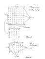
- the array of points represent a portion of the pixels of which an image is comprised.
- the indices of the pixel array are I (column) and L (row).
- the circles represent the subarray for which the chrominance parameters will be associated, the luminance parameters being associated with every pixel of the image array.
- the indices are represented by K (column) and J (row).
- the subarray of pixel locations designated by A, is comprised of every fourth pixel of every fourth row of the complete image array.
- an advantage value is obtained by using a 2-dimensional Gaussian weighting function.
- the luminance L is determined and stored for every pixel point P.
- the chrominance parameters S and T are determined for every point of the pixel array, but averaged chrominance parameters are retained only for the subarray of points A.
- the averaged chrominance parameters for each subarray pixel A, as shown in Fig. 1, include contributions from 49 neighboring array pixels.
- a two-dimensional Gaussian weighting procedure is used.
- S A and T A can be calculated in the following manner. where the summations are taken over the 49 pixels of the associated region.
- each determination of the luminance and the chrominance involves three multiplications and two additions.
- the color parameters are 8 bit signal groups.
- the signal groups can therefore taken on a maximum of 256 values.
- Look-up tables i.e., random access memories
- the results of the multiplication operations in addressable storage locations can be used to expedite the calculation.
- five constants are involved as indicated by the equations. Referring to the expanded area of Fig. 1, because of symmetry, only 10 weighting factor constants are required. Therefore, any multiplication operation can be avoided by using 15 256 address look-up tables (i.e., for the weighting constants and the transformation constants).
- the notation convention is illustrated where the pixel columns are labeled with an I, while the pixel rows are labeled with an L.
- the subarray points (A) use K to designate the columns and J to designate the rows.
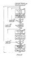
- Fig. 2 an algorithm that performs the transformation from the RGB (red, green, blue) parameters to the luminance/chrominance (YST) parameters is shown.
- the availability of signal image pixels is in the order that the pixel are typically displayed (i.e., on a cathode ray rube or CRT), scanning in the same direction across consecutive rows.
- the luminance parameter for each point is computed in step 202.
- the luminance parameter value and the red and blue pixel parameters for that pixel location are each entered in an associated shift register in step 203.
- the shift registers include seven rows, each row having 512 byte positions (i.e, the number of pixels per row in the image). Then, in step 204, a determination is made whether the end of the image row has been reached. If the end of the image row has not been reached, then the column index (I) is incremented in step 205 and the loop is continued until the end of the row is reached in step 204. When the comparison of step 204 yields a positive result, then a comparison is made to determine whether the seven rows of the shift register are filled.
- step 206 When this comparison is not true, the next row of image pixels is addressed, the luminance parameters are determined and the parameters are entered in the next row of the shift register. This process loop is continued until the shift registers are filled.
- step 208 the comparison of step 206 will yield a positive result and the determination is made in step 208 if the boundaries of the image pixel array have values that are stored in the registers. The boundaries must be treated with a special algorithm because the full complement of pixel location is not available for subarray locations on the subarray boundary.
- the luminance parameters Y IL , R(red parameter) IL and B(blue parameter) IL are in corresponding shift register positions and the chrominance parameters S KJ and T KJ for the subarray point can be determined by calculating the pixel chrominance parameters for each array location and by weighting and summing these parameters for association with this subarray point.
- a test is then made in step 210 whether the previous computations were for the last subarray point in the row. When the computations were not for the last subarray point of the row, then the K index is incremented in step 211, and the same computations can be performed on the next sequential subarray point of the row.
- step 210 When computations for the last subarray point of the row have been performed, then comparison of step 210 will provide a true result and the registers storing the R IL and the B IL parameters will shift the earliest stored three rows from the shift register in such a manner that newly stored parameters will be symmetrically placed with respect to the next subarray rows.
- This shifting is performed in step 212, and in step 213, the I, J, K and L indices are all set and the procedure returned to step 202.
- the procedure will continue until the step 208 determines that the pixel array has been completely processed and initiates the appropriate procedure, e.g., begins processing the next image.
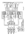
- Color parameter input units 301, 302 and 303 receive the image pixel red, green and blue parameters, respectively.
- the output signals from color parameter input units 301, 302 and 303 are applied to C R R table unit 304, to C G G table unit 305 and to C B B table unit 306 respectively.
- the output signals from the table unit 304, 305 and 306 are the contributions to the luminance Y from the pixel color components at that image location. The contributions are combined in summation unit 307 (c.f. step 202 in Fig 2).
- the red parameter at the pixel point is stored in red parameter row and pixel unit 311, the blue parameter is stored in a corresponding location in blue parameter row and pixel unit 312 and the luminance parameter from summation unit 307 is stored in a corresponding location in Y parameter row and pixel unit 308 (c.f. step 203 in Fig. 2).
- the luminance parameter is preserved for all pixel locations so that the output signals from unit 308 can be applied to the frame buffer and data bus 351 for storage or transmission.
- the S parameter must be determined for all the pixels of the region of the subarray point, and the resulting quantity weighted by the two-dimensional Gaussian weighting function of each pixel of the subarray point.
- each region pixel is determined by applying the pixel chrominance S parameter to the table that has, in a location corresponding to the location relative to the associated subarray point, the corresponding weighted parameter stored in pixel weighting constant table 314.
- the subarray region weighted chrominance S parameters are summed in S parameter accumulation unit 315.
- T parameter accumulation units 316 A similar procedure is implemented in T parameter accumulation units 316.
- the output signals from the parameter accumulation units 315 and 316 are applied to frame buffer address and data buffer 351 at a pixel address determined by address counter 322.
- Special case logic unit 313 controls the chrominance parameter determination for the boundary locations of the subarray point where, because of the location on the array boundary, the full region of neighboring pixel locations is not available.
- the special case logic unit 313 can, for example, insert mid-range parameter values for the missing location parameter values, or the special case logic can multiply the available parameter values by a weighting constant, a procedure that can be equivalent to assuming that the the available parameter values represent a suitably weighted average value for the unavailable parameter values.
- the pixel and row counter unit 320 controls the synchronization of the transformation (or encoding) unit and the pixel and row compare unit 321 provides the decision apparatus used in steps 204, 206 and 210 of Fig. 2. This unit provides the control for entering new rows of color parameters when a row of subarray computations is complete.
- Parameter units 311, 312 and 308 can include shift registers and are adapted to store pixel parameters for seven rows of pixels. Because the shift registers store pixel parameters in corresponding register locations, the requisite data are simultaneously available in S parameter accumulator unit 315 and T parameter accumulator unit 316.
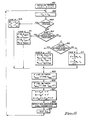
- Fig. 4 the process for recovering the color (RGB) from the encoded luminance and chrominance (YST) parameters is illustrated.
- the subarray points indicated by A in Fig. 4 have luminance and chrominance values associated therewith.
- every pixel location has a luminance value associated therewith.
- the luminance Y is known.
- the chrominance parameters can be determined from the equations: where S ⁇ and T ⁇ indicate that these are reconstructed parameters and the weighting constant W ⁇ il are bilinear weighting constants.
- the pixel location for which the color parameters are desired is also a subarray location.
- the subarray chrominance parameters are the pixel chrominance parameters.
- the pixel location is on a row between two subarray locations.
- the pixel chrominance parameters are linear combinations of the bounding subarray point chrominance parameters. (This situation is designated as Case C in Fig. 5 and Fig. 6).
- the pixel location can be on a column between the two subarray locations and the reconstructed chrominance parameters are linear combinations of the chrominance parameters of the subarray location bounding the pixel locations.
- This situation is designated as Case D in Fig. 5 and Fig. 6).
- the pixel location can be none of the special categories and the reconstructed chrominance parameters will be a combination of the four subarray locations bounding the pixel locations as described in the equations above. (This situation is designated as Case B in Fig. 5 and Fig. 6).
- step 501 the subarray row (J) and column (K) indices along with the pixel column (I) and row (L) indices are initialized (e.g., by entering a 1 in appropriate counters).
- step 502 the luminance value Y IL at the current location is designated as the reconstructed luminance value Y ⁇ IL at the location.
- step 503 the determination is made whether the current pixel location is a subarray location. When the determination is made that a subarray location is currently being addressed, then the S JK is used as the S ⁇ JK and T JK is used as the T ⁇ JK .
- step 507 the Red ⁇ , Green ⁇ and Blue ⁇ parameters can be calculated using equations 4, 5 and 6.
- the resulting image color parameters are provided in step 508.
- step 509 the column index is incremented by 1 and the process is returned to step 502.
- the row index is incremented by one and the column index is set equal to one in step 509.
- step 510 a determination is made whether the current pixel location falls on a row between subarray locations.
- the output signals from step 511 include the Y ⁇ , S ⁇ and T ⁇ parameters for the current location and the color parameters (R ⁇ , G ⁇ , B ⁇ ) are calculated in step 507 and provided to the display or storage circuit is step 508. The next sequential pixel location is then disignated as the current pixel location in step 509.
- step 510 the determination is made that the current pixel location is not on a row between two subarray locations
- the S ⁇ LI and the T ⁇ LI chrominance parameters can be calculated as a linear combination of the corresponding chrominance values of the bounding subarray points similar to equations for the pixel locations on a row bounded by subarray locations. Because the Y ⁇ S ⁇ and T ⁇ parameters are now available at the currently designated pixel location, the color parameters for the currently designated pixel can be reconstructed in step 507 and the step 509 can designate the next sequential pixel location as the current pixel location.
- step 514 the S ⁇ LI and T ⁇ LI chrominance values are determined, as indicated previously, by a linear combination of the S JK and T JK chrominance values of the surrounding subarray locations.
- W p is the appropriate bilinear weighting coefficient, which depends on the relative location of the pixel to the subarray.
- steps 505 and 506 provide for a situation where, because Y ⁇ is the true luminance parameter for a point, but S ⁇ and T ⁇ are averaged parameters, the S ⁇ and T ⁇ parameter at that location can be incompatible with the Y ⁇ parameter. Knowing the Y ⁇ parameter, the allowable ranges for the S ⁇ and the T ⁇ parameters are known and the steps 505 and 506 "force" the S ⁇ and T ⁇ into the allowable range.
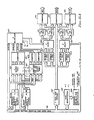
- a block diagram of apparatus capable of implementing the algorithm described by Fig. 5 is shown.
- the luminance and chrominance are supplied to the frame buffer address and data bus 351.
- Y pixel row storage unit 601 the Y LI parameters for all the pixel locations of the row with the current pixel location are entered.
- the S JK parameters for the subarray row are entered in the previous subarray row S storage unit 602 while the equivalent subarray row T JK parameters are entered in the previous subarray row T storage until 604.
- the current subarray S parameter is located in the top left (TL) register location of S storage unit 602.
- This parameter which in this situation is used as the S ⁇ chrominance select value, is applied through the S multiplexer unit 607 to the S ⁇ select unit 608.
- the transformation constant of the S ⁇ value needed to obtain the red color parameter is found by addressing a look-up table in the C ⁇ RS table unit 611 with the output of the S ⁇ register, the output of the table unit 611 being applied to summation unit 615.
- the Y parameter which is the Y ⁇ parameter for the current pixel location, is also applied to summation unit 615.
- the summation unit 615 combines the two input signals to provide the R ⁇ (reconstructed red) pixel component for current pixel location.
- the T chrominance paremater stored in the top left (TL) position of previous subarray row T storage unit 604 is applied through the T multiplexer unit 609 and T ⁇ select unit 609 to a look-up table in C ⁇ BT table unit 614.
- the output signal of table unit 614 is combined with the value of Y ⁇ (Y) in summation unit 616 to provide the B ⁇ (reconstructed blue) pixel value for the current pixel location.
- the output signal of the S ⁇ register is applied to a look-up table in the C ⁇ GS table unit 612 and the output signal from the T ⁇ register is applied to a look-up table in the C ⁇ GT table unit 613.
- the output signals of the table unit 612 and the table unit 613 are applied together with the Y ⁇ parameter to the summation unit 610, the output signal of the summation network 610 being the G ⁇ (reconstructed green) pixel parameter for the current pixel.
- the output signal of the summation network 610 being the G ⁇ (reconstructed green) pixel parameter for the current pixel.
- Case B (cf. Fig. 5) can be understood as follows.
- the previous subarray row S unit 602 contains S chrominance parameters for a pixel row for which the transformation to the color parameters has already taken place. (During the activity involving the first subarray row, this row can be the current row.)
- the next subarray row S storage unit 603 has S chrominance parameters entered therein for the next consecutive subarray row.
- the current pixel row Y storage unit register 601 includes the pixel luminance parameters for the current pixel row.
- the S chrominance parameter stored in the top left (TL) position of register 602 is applied to a look-up table in S weight table unit 617, addressing a table determined by the relative position of the current pixel location and the subarray location associated with the TL position of storage unit 602.
- the second (of four) S chrominance parameters that comprises the S ⁇ chrominance parameter is located in the top right (TR) position of the storage unit 602, and this parameter is simultaneously applied to a look-up table in the S weight table unit 617, the table being addressed determined by the relative position of the current pixel and the subarray location associated with the TR position of the line store register 602.
- next row S storage unit 603 has the S chrominance parameters stored therein applied to look-up tables in S weight table unit 617 determined by the relative position of the current pixel location and the subarray locations associated with BL and BR positions.
- the output signals from the addressed tables of S weight table unit 617 are applied to summation unit 621 where they are combined.
- the resulting value is applied through S multiplexer unit 607 and stored in S ⁇ select unit 608.
- This procedure implements the general equation for the determination of the reconstructed S ⁇ chrominance parameter when four neighboring subarray locations contribute to the parameter as illustrated in step 514.
- the reconstructed T ⁇ chrominance parameter is derived from the TL and TR positions of the previous subarray row T storage unit 604 and the BL and BR positions of the next subarray row T storage unit 605.
- Case C and Case D can be understood in the following manner.
- the current pixel for which the reconstructed color parameters must be determined, lies in a row between two subarray pixel locations.
- Case D is similar, the difference being that the current pixel location falls on column between two subarray pixel locations.
- the weighting factors W ⁇ x and W ⁇ 4-x are the same for the two situations and depend on which of the three intermediate pixel locations (i.e., between the subarray pixel locations) is designated as the current pixel location.
- the current pixel location can lie between the subarray pixel location associated with positions TL and TR of the previous subarray row S storage unit 602 or BL and BR positions of the next subarray row S storage unit 603.
- the appropriate two S parameters are applied to the S subarray row and column weight table unit 619, the parameters being applied to a look-up table determined by the particular intermediate pixel location.
- the output signals from the weight table unit 619 is combined in summation unit 622 and the resulting reconstructed parameter S ⁇ is applied through S multiplexer unit 607 to the S ⁇ select unit 608.
- a similar procedure involving the TL and TR positions of the previous subarray row T storage unit 604 or the BL and BR positions of the next subarray row T storage unit 605 and involving T subarray column and row weight table unit 620 and summation unit 625 provides a reconstructed T ⁇ parameter when the current pixel location lies on a row between two subarray pixel locations.
- the subarray pixel locations would be associated with the TL position of the previous subarray row S storage unit 602 and the BL position of the next subarray row S storage unit 603 or would be associated with the TR position of the storage unit 602 and the BR position of the storage unit 603.
- the S chrominance parameters of the appropriate storage units position pair is applied to look-up tables in S subarray row and column weight table 619 the particular look-up tables for the signals determined by the particular current pixel location relative to the subarray pixels.
- the output signals from the look-up tables are combined in summation unit 623, providing a reconstructed S ⁇ parameter and applied through S multiplexer unit 607 to S ⁇ unit 608.
- the T ⁇ chrominance parameter can be determined in a similar manner utilizing the previous subarray row T storage unit 604, the next subarray row T storage unit 605, the subarray column and row weight tables unit 620, the summation unit 626 and the T multiplexer unit 608.
- the averaging of the chrominance parameters can result in unpermitted S ⁇ and T ⁇ parameters when compared with the Y ⁇ luminance parameter.
- the value of the Y ⁇ parameter from Y pixel row storage unit 601 is applied to max(imum) S ⁇ table unit 631, min(imum) S ⁇ table unit 632, max T ⁇ table unit 633 and to min T ⁇ table unit 634.
- the output signals from table units 631 and 632 establish the range of allowable values for S ⁇ and are applied to the S ⁇ select unit and insure that the parameter in S ⁇ select unit 608 is within the allowable range.
- the table units 633 and 634 similarly determine the allowable range of values for T ⁇ and insure that the parameter stored in the T ⁇ select unit 609 is within the allowable range.
- Fig. 6 the position of the current pixel location is designated in pixel identification unit 627.
- the multiplexer units 608 and 607 are controlled by the subarray column and row identification unit 628.
- the chrominance parameters for all cases are determined, but only the appropriate parameter transmitted for further processing.
- the use of look-up tables avoids the need for a multiply operation.
- the parameter length (8 bits) can be easily accommodated by look-up table procedure with a substantial increase in operation speed.
- the number of constants is similarly limited because of the symmetry of the pixel locations relative to the subarray pixel locations.
- chromatic definition in the image is reduced.
- the reduction in definition is not objectionable.
- the image blurring can be unacceptable.
- a storage location can be associated with each array or subarray pixel location and a signal in that storage location results in the interpretation of the luminance parameter as one of a predetermined group of colors.
- the luminance parameter can be applied to a random access memory, the parameter causing an RGB color parameter group to be available without additional processing.
- the present invention reduces the amount of information required to represent a color image by systematically providing, at periodic pixel subarray locations, a value for the two chrominance parameters that are weighted averages of these parameters at pixels surrounding the pixel subarray locations. Similarly, when the luminance/chrominance parameters are converted to the color parameters, a weighted value of the two processed chrominance parameters at neighboring pixel subarray locations are used to reconstruct (approximately) the original color parameters. The process is somewhat more complicated at the boundaries of the image where the general procedure would require quantities from points that are not in the image.
- the conversion process in either direction is expedited by using RAM memories as look-up tables to eliminate the requirement for a multiplication operation.
- the number of the required RAM memories is reduced by observing the symmetries of the weighting process.
- the limited possible number of parameter values i.e., 256 values for 8 bit parameters contributes to the ability to replace the multiplication operation by a table addressing (look-up) operation.
- every fourth row pixel and every fourth column pixel is not a requirement.
- Other subarrays could be employed to achieve the same benefits in the reduction of information required to store an image.
- the periodicity of the subarray with respect to the image array permits the use of shift registers to allow associated pixel parameters to be placed in a location for processing.
- the luminance/chrominance parameters are well defined intermediate parameters. However, it will be clear that the invention will effectively reduce the information required to reproduce an image when the intermediate parameters are the result of a more general transformation from the color parameters to the intermediate parameters.
- the information reduction represent an image of the present invention has two complications for which provision must be made.
- the deminished number of pixel locations for subarray locations close to the boundary must have a special provision made to insure that non-representative values are not developed.
- the fact that the chrominance parameters are averaged quantities while the luminance parameter is the true value at a pixel can result in erroneous reconstruction color parameters.
- the luminance parameter implies that the two chrominance parameters must fall within a predetermined range. Therefore, the apparatus of the present invention includes a network that determines the allowable chrominance parameters for a given luminance parameter and insures that the chrominance parameters used in reconstructing the color parameters fall within the allowable range.
- the present invention produces an averaging effect for color parameters that is generally not noticeable. However, for regions requiring sharp contrast such as a line display or a line through an image, the blurring effect can be unacceptable.
- a signal storage unit can be associated with each pixel. When a signal is in the storage unit, the luminance parameter for that pixel is replaced by a signal group that designates a color parameter combination. When the color parameters are reconstructed, the presence of the signal causes the associated pixel to have the designated color parameter location associated therewith.
Landscapes
- Engineering & Computer Science (AREA)
- Signal Processing (AREA)
- Multimedia (AREA)
- Computer Networks & Wireless Communication (AREA)
- Image Processing (AREA)
- Processing Of Color Television Signals (AREA)
- Color Image Communication Systems (AREA)
- Controls And Circuits For Display Device (AREA)
- Digital Computer Display Output (AREA)
Applications Claiming Priority (2)
| Application Number | Priority Date | Filing Date | Title |
|---|---|---|---|
| US07/018,491 US4835599A (en) | 1987-02-25 | 1987-02-25 | Apparatus and method for storing and transmitting images represented by logic signals |
| US18491 | 1987-02-25 |
Publications (2)
| Publication Number | Publication Date |
|---|---|
| EP0283627A2 true EP0283627A2 (fr) | 1988-09-28 |
| EP0283627A3 EP0283627A3 (fr) | 1991-09-11 |
Family
ID=21788199
Family Applications (1)
| Application Number | Title | Priority Date | Filing Date |
|---|---|---|---|
| EP19870401706 Withdrawn EP0283627A3 (fr) | 1987-02-25 | 1987-07-22 | Appareil et méthode pour mémoriser et transmettre des images représentées par des signaux logiques |
Country Status (6)
| Country | Link |
|---|---|
| US (1) | US4835599A (fr) |
| EP (1) | EP0283627A3 (fr) |
| JP (2) | JPS63209390A (fr) |
| KR (1) | KR920003374B1 (fr) |
| AU (1) | AU596200B2 (fr) |
| CA (1) | CA1323685C (fr) |
Cited By (1)
| Publication number | Priority date | Publication date | Assignee | Title |
|---|---|---|---|---|
| WO2003071782A1 (fr) * | 2002-02-22 | 2003-08-28 | Sony United Kingdom Limited | Appareil et procede de traitement d'images |
Families Citing this family (16)
| Publication number | Priority date | Publication date | Assignee | Title |
|---|---|---|---|---|
| US5594812A (en) * | 1990-04-19 | 1997-01-14 | Ricoh Corporation | Apparatus and method for compressing still images |
| US5129015A (en) * | 1990-04-19 | 1992-07-07 | Ricoh Company Ltd. | Apparatus and method for compressing still images without multiplication |
| US5546105A (en) * | 1991-07-19 | 1996-08-13 | Apple Computer, Inc. | Graphic system for displaying images in gray-scale |
| US5625713A (en) * | 1991-08-09 | 1997-04-29 | Ricoh Corporation | Apparatus and method for increasing the throughput of an acoustic or image compression system |
| US5398077A (en) * | 1992-05-19 | 1995-03-14 | Eastman Kodak Company | Method for adjusting the luminance of a color signal |
| US5495345A (en) * | 1992-10-15 | 1996-02-27 | Digital Equipment Corporation | Imaging system with two level dithering using comparator |
| US5535020A (en) * | 1992-10-15 | 1996-07-09 | Digital Equipment Corporation | Void and cluster apparatus and method for generating dither templates |
| US5333260A (en) * | 1992-10-15 | 1994-07-26 | Digital Equipment Corporation | Imaging system with multilevel dithering using bit shifter |
| US5333262A (en) * | 1992-10-15 | 1994-07-26 | Ulichney Robert A | Imaging system with multilevel dithering using two memories |
| US5543936A (en) * | 1992-10-15 | 1996-08-06 | Digital Equipment Corporation | Image adjustment system for translating raw input levels to adjusted input levels |
| US5602941A (en) * | 1993-05-21 | 1997-02-11 | Digital Equipment Corporation | Input modification system for multilevel dithering |
| US5510852A (en) * | 1994-04-28 | 1996-04-23 | Winbond Electronics, Corp. | Method and apparatus using symmetrical coding look-up tables for color space conversion |
| US6487308B1 (en) * | 1996-05-22 | 2002-11-26 | Compaq Computer Corporation | Method and apparatus for providing 64-bit YUV to RGB color conversion |
| US5990876A (en) * | 1996-12-10 | 1999-11-23 | Winbond Electronics Corp. | Method and apparatus with reduced look-up tables for converting RGB color space signals to YCbCr color space signals |
| US5963263A (en) | 1997-06-10 | 1999-10-05 | Winbond Electronic Corp. | Method and apparatus requiring fewer number of look-up tables for converting luminance-chrominance color space signals to RGB color space signals |
| US6049399A (en) * | 1997-11-04 | 2000-04-11 | Winbond Electronics Corp. | Method and apparatus with reduced look-up tables for converting luminance-chrominance color space signals to RGB color space signals |
Family Cites Families (6)
| Publication number | Priority date | Publication date | Assignee | Title |
|---|---|---|---|---|
| DE3211323C2 (de) * | 1982-03-27 | 1984-02-09 | Standard Elektrik Lorenz Ag, 7000 Stuttgart | System zur redundanzvermindernden digitalen Übertragung von Fernsehbildsignalen |
| EP0125268B1 (fr) * | 1982-10-29 | 1987-04-22 | Devon County Council | Appareil de codage/decodage de signaux |
| US4597005A (en) * | 1984-04-26 | 1986-06-24 | Canadian Patents And Development Limited | Digital color photographic image video display system |
| AU5010085A (en) * | 1984-12-06 | 1986-06-12 | Sony Corporation | Rgb double line rate conversion |
| CA1251555A (fr) * | 1984-12-19 | 1989-03-21 | Tetsujiro Kondo | Methode a rendement eleve pour coder les signaux video numerique |
| JPH0793724B2 (ja) * | 1984-12-21 | 1995-10-09 | ソニー株式会社 | テレビジョン信号の高能率符号化装置及び符号化方法 |
-
1987
- 1987-02-25 US US07/018,491 patent/US4835599A/en not_active Expired - Lifetime
- 1987-07-06 CA CA000541397A patent/CA1323685C/fr not_active Expired - Fee Related
- 1987-07-17 AU AU75930/87A patent/AU596200B2/en not_active Ceased
- 1987-07-22 EP EP19870401706 patent/EP0283627A3/fr not_active Withdrawn
- 1987-10-14 KR KR1019870011412A patent/KR920003374B1/ko not_active Expired
-
1988
- 1988-02-16 JP JP63031971A patent/JPS63209390A/ja active Pending
-
1992
- 1992-04-08 JP JP4087197A patent/JPH05241550A/ja active Pending
Cited By (2)
| Publication number | Priority date | Publication date | Assignee | Title |
|---|---|---|---|---|
| WO2003071782A1 (fr) * | 2002-02-22 | 2003-08-28 | Sony United Kingdom Limited | Appareil et procede de traitement d'images |
| US7580561B2 (en) | 2002-02-22 | 2009-08-25 | Sony United Kingdom Limited | Image processing apparatus and method |
Also Published As
| Publication number | Publication date |
|---|---|
| KR880010585A (ko) | 1988-10-10 |
| JPS63209390A (ja) | 1988-08-30 |
| KR920003374B1 (ko) | 1992-04-30 |
| JPH05241550A (ja) | 1993-09-21 |
| AU596200B2 (en) | 1990-04-26 |
| AU7593087A (en) | 1988-09-01 |
| US4835599A (en) | 1989-05-30 |
| CA1323685C (fr) | 1993-10-26 |
| EP0283627A3 (fr) | 1991-09-11 |
Similar Documents
| Publication | Publication Date | Title |
|---|---|---|
| EP0283627A2 (fr) | Appareil et méthode pour mémoriser et transmettre des images représentées par des signaux logiques | |
| EP0597555B1 (fr) | Appareil de traitement d'images | |
| US5563718A (en) | Image coding by use of discrete cosine transforms | |
| US4958225A (en) | Full-search-equivalent method for matching data and a vector quantizer utilizing such method | |
| EP0576786B1 (fr) | Processeur de diffusion d'erreurs et procédé pour la conversion d'une image à élémwents à échelle de gris dans une image à éléments de valeur binaire | |
| US5832132A (en) | Image processing using neural network | |
| EP0614309A2 (fr) | Appareil de traitement d'image | |
| EP0772158A2 (fr) | Système de traitement d'image | |
| EP0159691A2 (fr) | Système de visualisation d'images en couleurs | |
| JPH07162848A (ja) | ディジタル画像信号の処理装置 | |
| US4853794A (en) | Method and image processing system for reconstruction of an image | |
| US4866514A (en) | Image processing having a second set of look-up-tables (LUTS) for generating error value signals | |
| US5214751A (en) | Method for the temporal interpolation of images and device for implementing this method | |
| EP0351062B1 (fr) | Procédé et appareil pour la génération d'images composites | |
| US5434931A (en) | System and method for picture image processing employing transformation of picture data | |
| US5041916A (en) | Color image data compression and recovery apparatus based on neural networks | |
| JPH08317197A (ja) | 画像処理装置 | |
| WO1995015530A1 (fr) | Codage d'images par transformations en cosinus discretes | |
| US6731822B1 (en) | Method and apparatus for filtering images having insufficient tonal precision | |
| EP0783224A2 (fr) | Diffusion d'erreurs avec un masque de réduction géométrique | |
| JP3245600B2 (ja) | 画像処理装置 | |
| US6823085B1 (en) | Image data compression and reconstruction apparatus and method and storage medium thereof | |
| JP2941288B2 (ja) | 画像処理システム | |
| JP3184197B2 (ja) | 画像処理装置 | |
| JPS63232571A (ja) | 擬似中間調処理装置 |
Legal Events
| Date | Code | Title | Description |
|---|---|---|---|
| PUAI | Public reference made under article 153(3) epc to a published international application that has entered the european phase |
Free format text: ORIGINAL CODE: 0009012 |
|
| AK | Designated contracting states |
Kind code of ref document: A2 Designated state(s): AT BE CH DE ES FR GB GR IT LI LU NL SE |
|
| PUAL | Search report despatched |
Free format text: ORIGINAL CODE: 0009013 |
|
| AK | Designated contracting states |
Kind code of ref document: A3 Designated state(s): AT BE CH DE ES FR GB GR IT LI LU NL SE |
|
| 17P | Request for examination filed |
Effective date: 19920215 |
|
| 17Q | First examination report despatched |
Effective date: 19930525 |
|
| STAA | Information on the status of an ep patent application or granted ep patent |
Free format text: STATUS: THE APPLICATION IS DEEMED TO BE WITHDRAWN |
|
| 18D | Application deemed to be withdrawn |
Effective date: 19931207 |
|
| RIN1 | Information on inventor provided before grant (corrected) |
Inventor name: SIGEL, CLAUDE A. |