EP0283650B1 - Appareil de mesure pour la configuration de composants en forme de vis - Google Patents
Appareil de mesure pour la configuration de composants en forme de vis Download PDFInfo
- Publication number
- EP0283650B1 EP0283650B1 EP19880100720 EP88100720A EP0283650B1 EP 0283650 B1 EP0283650 B1 EP 0283650B1 EP 19880100720 EP19880100720 EP 19880100720 EP 88100720 A EP88100720 A EP 88100720A EP 0283650 B1 EP0283650 B1 EP 0283650B1
- Authority
- EP
- European Patent Office
- Prior art keywords
- measuring device
- coils
- coil
- screw
- measuring
- Prior art date
- Legal status (The legal status is an assumption and is not a legal conclusion. Google has not performed a legal analysis and makes no representation as to the accuracy of the status listed.)
- Expired - Lifetime
Links
Images



Classifications
-
- B—PERFORMING OPERATIONS; TRANSPORTING
- B07—SEPARATING SOLIDS FROM SOLIDS; SORTING
- B07C—POSTAL SORTING; SORTING INDIVIDUAL ARTICLES, OR BULK MATERIAL FIT TO BE SORTED PIECE-MEAL, e.g. BY PICKING
- B07C5/00—Sorting according to a characteristic or feature of the articles or material being sorted, e.g. by control effected by devices which detect or measure such characteristic or feature; Sorting by manually actuated devices, e.g. switches
- B07C5/04—Sorting according to size
- B07C5/08—Sorting according to size measured electrically or electronically
- B07C5/086—Magnetic sensing devices
-
- G—PHYSICS
- G01—MEASURING; TESTING
- G01B—MEASURING LENGTH, THICKNESS OR SIMILAR LINEAR DIMENSIONS; MEASURING ANGLES; MEASURING AREAS; MEASURING IRREGULARITIES OF SURFACES OR CONTOURS
- G01B7/00—Measuring arrangements characterised by the use of electric or magnetic techniques
- G01B7/28—Measuring arrangements characterised by the use of electric or magnetic techniques for measuring contours or curvatures
- G01B7/284—Measuring arrangements characterised by the use of electric or magnetic techniques for measuring contours or curvatures of screw-threads
Definitions
- the invention relates to a measuring device for contactless detection of the shape of metallic helical components according to the preamble of the main claim.
- a measuring device for contactless detection of the shape of metallic helical components according to the preamble of the main claim.
- Such a measuring device is already known in which the shape of screws is determined using an optical method. The shape of the screws is scanned with a light beam.
- the complete shape of the screws arranged on a continuously running belt cannot be checked in a single operation. This leaves faulty screws, which can only be sorted out with the help of a second test procedure. This makes the measuring device complex and expensive.
- the measuring method is easily affected by dirt particles. Faults that are on the circumference or on the surface of the screw cannot be detected with the optical method.
- the different types of screws such as hexagon socket head screws or Phillips screws, cannot be recognized, since the inner contours of the screws cannot be checked optically or only with great effort.
- a measuring device for contactless detection of the shape of screws is known, in which the shape of the screws is determined with at least one optical transmitter and receiver.
- the optical sensors it is only possible to use the optical sensors to check a special shape, for example the length of the screw or the head shape of the screw.
- This measuring system is particularly susceptible to errors, especially when the screws are dirty.
- US Pat. No. 3,883,796 describes how to determine the shape of components with the aid of a coil through which an alternating current flows and a corresponding evaluation circuit.
- the measuring principle is based on the determination of the different distance between the components and the coil. As a result, only measurement errors that are clearly based on a change in distance from the coil can be determined. If the components roll past the coil, different measurement errors that may occur on one component can compensate each other so that a defective component is not recognized as defective.
- the device according to the invention with the features of claim 1 has the advantage that the complete shape of the screw, both its shape and its length, can be detected relatively safely in a single operation.
- the measuring device can be used very simply in a continuous, automatically running work process.
- the accuracy of the signals to be measured is improved so that the screws can be sorted out even with the smallest tolerance ranges.
- the remaining reject rate is very low.
- Interference from the environment, e.g. Temperature are eliminated.
- the maintenance effort is low.
- Several screw error parameters can be recognized simultaneously or in succession. In particular, the quality of the screws, e.g. for cracks.
- the measuring device can be used without restriction for all types of metal screws that can be sorted out on the sorter without major modifications.
- a special embodiment according to claim 15 when changing the quality and shape of the screws to be checked, no new values need to be entered in the test electronics. Rather, it is sufficient if the reference part is exchanged, which shortens the changeover time, since the readjustment of the evaluation electronics is largely eliminated.
- FIG. 1 shows a longitudinal section through a linear conveyor with different screws
- FIG. 2 shows a section in the direction A of FIG. 1
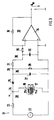
- FIG. 3 shows a circuit diagram
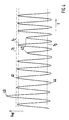
- FIG. 4 shows a diagram with the course of the measuring voltage U M over time t
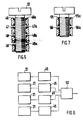
- FIGS. 5 and 7 each a modification of the exemplary embodiment
- FIGS. 6 and 9 each a circuit diagram belonging to the exemplary embodiments according to FIGS. 5 and 7,
- FIG. 8 a circuit of the coils for the exemplary embodiment
- FIG. 7 a further modification of the exemplary embodiment
- FIG. 11 a modification of the exemplary embodiment for Determination of the screw head contour
- FIG. 1 10 denotes the feed rail of a linear conveyor 11, 12 screws 13 hang in the slot 12.
- the two side walls 14, 15 of the slot 12 there is one coil 16, 17, as can be seen in more detail in FIG.
- An oval coil shape is also possible.
- a relatively large area of the shaft 18 of the screw 13 is covered, the coils themselves being as narrow as possible.
- FIG. 1 several different screw shapes are drawn in the linear conveyor 11 in order to show the variety of the screws to be monitored and their errors.
- the two coils 16, 17 are connected in series and in an evaluation circuit 21 shown in FIG.
- An AC generator 22 feeds the coils 16, 17 with a high-frequency AC voltage via a series resistor 23.
- a sensor signal 24 can be removed from the coils 16, 17 and is supplied via a diode 25, a filter circuit 26, consisting of a filter capacitor 27 and a bleeder resistor 28.
- the screened signal voltage 29 passes through a low-pass arrangement 30, which is formed from a resistor 31 and a capacitor 32, into an amplifier arrangement 33.
- the amplifier arrangement 33 is designed as an inverting operational amplifier circuit 34, the gain factor of which can be set with the two resistors 35, 36.
- the two coils 16, 17 can be connected to one another in a voltage divider circuit 38 or, as shown in FIG. 8, in a so-called half-bridge circuit or in a branch of a Wheatstone bridge.
- the course of the measuring voltage U M is plotted against the time t, that is to say while the screws 13 pass through the two coils 16, 17.
- the diagram is obtained as follows:
- the voltage values 24 present at point ⁇ are mirrored by the subsequent inverting operational amplifier circuit 33 and additionally raised to the positive voltage range by an auxiliary circuit (not shown).
- auxiliary circuit not shown
- faulty screw geometries a screw that is too short, a screw with a faulty thread cut, a conical self-tapping screw, or even quality defects can be recognized. If, on the other hand, the threads are in order, measurement signals 41 of almost the same level are obtained.
- a signal processing electronics 45 shown in Figures 6 and 9 delimits the range with the trigger voltages T 1 and T 2, i.e. the setpoint range, in which the height of the measurement signals 41 for correct screws 13 should form.
- the trigger voltages T1 and T2 are the predetermined limit ranges of the desired tolerances of the screws 13. The larger this range, the larger the tolerance range for the respective screws 13.
- a third trigger voltage T3 is provided in the signal processing electronics 45. When this trigger voltage T3 is reached, if the screws are incorrectly designed and consequently generate measurement signals that are outside the tolerance range of T1 and T2, a control pulse is generated by the signal processing electronics 45, which causes faulty screws to be sorted out.
- the trigger voltages T 1, T 2 which can be set with a potentiometer are related to 0 volts or a fixed voltage value. Due to the so-called offset drift caused by the measuring system, the voltage values of the measuring signals can change, while the trigger voltages T 1, T 2 remain constant. Offset drift means the gradual change in the measured value U M due to environmental influences, for example heat, during the measurement. To increase the measuring accuracy, the trigger voltages T1, T2 are related to the previously applied minimum voltage value. As a result, the measurement errors caused by the so-called offset drift can be almost completely suppressed, since the minimum and maximum values of the measurement signal voltages change approximately equally. The prerequisite for this is, however, a shape that is as narrow as possible or rectangular or oval shaped coils 16, 17.
- 17 must be designed so closely that even if the coils 16, 17 are arranged in the middle between two successive shafts of screws with a minimal spacing, no or only a negligible small eddy current can form on the surfaces.
- FIGS. 5 to 9 show configurations of the coils 16, 17 and the associated electronics for additional refinement of the measurement signals U M obtained .
- the coils 16, 17 are divided into several sections 46 to 49. In Figure 5, these sections are shown as four individual coils arranged on each side. The reference numbers for the coils on the second side are supplemented with "a". However, a different number of coils or sections is also possible.
- Each of the opposing coils 46 and 46a are connected in series as above and in the voltage divider of the evaluation circuit 21.
- the measurement signal U M obtained in the evaluation circuit 21 is fed to the signal processing electronics 45 and thus converted into a digital signal.
- the voltage obtained from each individual pair of coils is determined and digitized in this way.
- a sorting system (not shown) can be controlled in the case of uniform digital signals.
- This logic circuit 53 has, in a manner known per se, logic components such as AND and OR gates. If the thread is not in order at one point, the digital signal of this area deviates from the other digital signals. The logic circuit 53 recognizes this deviation of the digital signal and causes the sorting system to eject this screw as faulty.
- both the shape of the thread and the length of the shaft 18 can be determined. This improves the detection of the length of the shaft 18 without significantly impairing the measurement signals U M with respect to the thread shape.
- all of the modifications outlined above, in particular in FIGS. 5 to 9, are also possible.
- the contour of the head 60 of a screw 61 can be checked in addition to the criteria already mentioned above or even alone. Both the type of head 60 and errors on the screw head 60 itself can be recognized.
- a coil 63 which works according to the eddy current measuring principle described above and can preferably be formed in a ring.
- the measurement signals U M shown in the diagram according to FIG. 4 are contained. However, since a constant distance c is assumed between the surface of the coil 63 and the contact surface 64 of the screw head 60, no second coil connected in series is necessary to compensate for the measurement errors.
- a positioning system for the screws 13 If a positioning system for the screws 13 is connected to the measuring device, it must be checked at the beginning of the positioning process whether there is a screw in the pliers jaw serving as the feed device 67 (see Figure 12).
- a coil 69 is arranged at the end of the feed channel 68 of the pliers jaw 67, as shown in FIG. 12a, which operates according to the eddy current principle as above.
- An evaluation of the measurement signal is possible with the circuit 21 shown in FIG. 3. For the detection of whether a screw 13 is already being fed or not, the measurement signal U M obtained at the output of the circuit 21 is sufficient.
- the screw 13 can then be screwed in with the aid of a screwdriver 70.
- the measuring device and thus the coils and the surfaces of the screws can be operated using the inductive method.
- the same conditions apply accordingly.
- the surfaces of the screws must then consist of ferromagnetic material. Therefore, only screws made of ferromagnetic material or with such a surface can be sorted out using the inductive method.
- screws made of ferromagnetic material e.g. Fe
- non-ferromagnetic but electrically conductive material e.g. Al, Zn
- FIG. 13 Another possibility of checking the screw shaft is shown in FIG. 13.
- the screw 71 to be checked is compared with a reference screw 72.
- the screw 71 and the reference screw 72 are each in a coil 73 of the same design, which is operated according to the eddy current principle as above and are connected in a Wheatstone bridge shown in FIG.
- the measurement signals generated are again evaluated analogously with the aid of the circuit 21.
- the screw 73 is introduced into a blind hole or into the bore of a nut.
Landscapes
- Physics & Mathematics (AREA)
- General Physics & Mathematics (AREA)
- Investigating Or Analyzing Materials By The Use Of Magnetic Means (AREA)
- Measurement Of Length, Angles, Or The Like Using Electric Or Magnetic Means (AREA)
- Measurement Of Resistance Or Impedance (AREA)
- Feeding Of Articles To Conveyors (AREA)
Claims (16)
- Appareil de mesure pour détecter sans contact la structure de composants (13) en forme de vis, réalisés en un matériau ferromagnétique et/ou non ferromagnétique mais conducteur d'électricité, cet appareil de mesure comprenant un rail de circulation (10) pour les composants (13) et au moins deux bobines (16, 17) opposées l'une à l'autre et traversées par un courant alternatif, les composants (13) passant par les bobines, les bobines (16, 17) étant branchées en série dans un montage en pont et reliées à un circuit d'exploitation électronique (21) et les tensions de mesure des bobines (16, 17) sont comparées à une valeur de consigne (T₁, T₂) prédéterminée.
- Appareil de mesure selon la revendication 1, caractérisé en ce que sont prévus un circuit électronique (45) pour transformer la tension de mesure fournie par les circuits d'exploitation (21) respectifs en un signal numérique, et un circuit logique (53) pour comparer les signaux numériques de toutes les bobines (16, 17).
- Appareil de mesure selon la revendication 1 et/ou 2, caractérisé en ce que chaque fois deux bobines en regard (16, 17) forment un diviseur de tension (38) ou la branche d'un pont de Wheatstone (55) faisant partie du circuit d'exploitation (21).
- Appareil de mesure selon l'une des revendications 1 à 3, caractérisé en ce que la longueur des bobines (16, 17) dépasse la longueur du composant (13).
- Appareil de mesure selon l'une des revendications 1 à 4, caractérisé en ce que les bobines (16, 17) sont subdivisées en plusieurs parties de bobine branchées en série.
- Appareil de mesure selon l'une des revendications 1 à 5, caractérisé en ce que chaque fois deux bobines (55, 55a) forment la branche d'un pont de Wheatstone (57) et les bobines (56, 56a) qui se trouvent en-dessous sont montées dans la branche opposée du pont de Wheatstone (57).
- Appareil de mesure selon l'une des revendications 1 à 6, caractérisé en ce que les bobines (16, 17) sont allongées et la largeur des bobines (16, 17) est suffisamment petite pour que lorsque les bobines se trouvent au milieu de l'intervalle minimum séparant deux composants (13) successifs, il ne se produise pas de courant de Foucault ou aucun courant négligeable.
- Appareil de mesure selon l'une des revendications 1 à 7, caractérisé en ce que le circuit électronique (45) présente deux tensions de déclenchement (T₁, T₂) réglables pour limiter la valeur de consigne.
- Appareil de mesure selon l'une des revendications 1 à 8, caractérisé en ce que les valeurs de consigne (T₁, T₂) sont rapportées à la valeur de mesure obtenue lors du positionnement de la bobine au milieu de l'intervalle minimum de deux composants successifs.
- Appareil de mesure selon l'une des revendications 1 à 9, caractérisé en ce que les signaux de mesure sont pris sur une tension de déclenchement (T₃) prédéterminée et celle-ci commande le classement des composants (13).
- Appareil de mesure selon l'une des revendications 1 à 10, caractérisé par une vis de référence placée dans un second appareil de mesure et qui fixe la valeur de consigne.
- Appareil de mesure selon l'une des revendications 1 à 11, caractérisé par au moins une bobine (63) en parallèle sur la tête (60) du composant (61).
- Appareil de mesure selon l'une des revendications 1 à 12, caractérisé en ce qu'il fonctionne suivant le principe des courants de Foucault.
- Appareil de mesure selon l'une des revendications 1 à 12, caractérisé en ce qu'il fonctionne suivant le principe inductif.
- Appareil de mesure selon l'une des revendications 1 à 14, caractérisé en ce que le composant (72) est plongé dans au moins une première bobine (73) et en ce qu'un composant de référence (71) est plongé dans au moins une seconde bobine (73) et en ce que les deux bobines (73) sont montées dans un pont de Wheatstone (74) qui fait partie du circuit d'exploitation électronique (21).
- Appareil de mesure selon la revendication 15, caractérisé en ce que les deux bobines (73) se composent de plusieurs parties de bobine branchées en série et ayant chacune un point de prise de signal.
Applications Claiming Priority (2)
| Application Number | Priority Date | Filing Date | Title |
|---|---|---|---|
| DE3706574 | 1987-02-28 | ||
| DE19873706574 DE3706574A1 (de) | 1987-02-28 | 1987-02-28 | Messeinrichtung fuer die gestalt von schraubenfoermigen bauteilen |
Publications (2)
| Publication Number | Publication Date |
|---|---|
| EP0283650A1 EP0283650A1 (fr) | 1988-09-28 |
| EP0283650B1 true EP0283650B1 (fr) | 1991-08-28 |
Family
ID=6322042
Family Applications (1)
| Application Number | Title | Priority Date | Filing Date |
|---|---|---|---|
| EP19880100720 Expired - Lifetime EP0283650B1 (fr) | 1987-02-28 | 1988-01-20 | Appareil de mesure pour la configuration de composants en forme de vis |
Country Status (3)
| Country | Link |
|---|---|
| EP (1) | EP0283650B1 (fr) |
| DE (2) | DE3706574A1 (fr) |
| ES (1) | ES2025706T3 (fr) |
Families Citing this family (3)
| Publication number | Priority date | Publication date | Assignee | Title |
|---|---|---|---|---|
| DE3905744A1 (de) * | 1989-02-24 | 1990-08-30 | Bosch Gmbh Robert | Messeinrichtung zur beruehrungsfreien erfassung der gestalt von bauteilen |
| DE8902231U1 (de) * | 1989-02-24 | 1990-06-21 | Robert Bosch Gmbh, 7000 Stuttgart | Meßeinrichtung zur berührungsfreien Erfassung der Gestalt von Bauteilen |
| CN115193744B (zh) * | 2022-07-22 | 2023-11-28 | 江苏金圣棋盘玻璃科技发展有限公司 | 一种化妆品包装瓶生产检测设备 |
Family Cites Families (5)
| Publication number | Priority date | Publication date | Assignee | Title |
|---|---|---|---|---|
| GB885639A (en) * | 1957-02-04 | 1961-12-28 | James Scott And Company Electr | Improvements in or relating to metal comparators |
| US3392829A (en) * | 1966-01-10 | 1968-07-16 | Continental Can Co | Container locating and vacuum sensing system |
| US3883796A (en) * | 1972-09-05 | 1975-05-13 | Acme Cleveland Corp | Proximity probe with output proportional to target distance |
| JPS5925170B2 (ja) * | 1978-07-08 | 1984-06-15 | 東洋製罐株式会社 | 密封容器の内圧検査法およびシステム回路装置 |
| US4457622A (en) * | 1982-01-27 | 1984-07-03 | Nhk Spring Co., Ltd. | Screw inspection device |
-
1987
- 1987-02-28 DE DE19873706574 patent/DE3706574A1/de not_active Withdrawn
-
1988
- 1988-01-20 EP EP19880100720 patent/EP0283650B1/fr not_active Expired - Lifetime
- 1988-01-20 DE DE8888100720T patent/DE3864430D1/de not_active Expired - Lifetime
- 1988-01-20 ES ES198888100720T patent/ES2025706T3/es not_active Expired - Lifetime
Also Published As
| Publication number | Publication date |
|---|---|
| DE3706574A1 (de) | 1988-09-08 |
| EP0283650A1 (fr) | 1988-09-28 |
| DE3864430D1 (de) | 1991-10-02 |
| ES2025706T3 (es) | 1992-04-01 |
Similar Documents
| Publication | Publication Date | Title |
|---|---|---|
| DE2912712A1 (de) | Messanordnung zum nachweis eines in papier, insbesondere in einem wertschein eingebetteten metallischen fadens | |
| DE3727416C2 (fr) | ||
| DE10014348B4 (de) | Vorrichtung zur zerstörungsfreien Messung der Dicke dünner Schichten | |
| EP0213283A1 (fr) | Dispositif pour l'examen de pièces de monnaie | |
| EP0062279A1 (fr) | Méthode pour détecter le bord d'un support magnétique et dispositif en voie de réliser cette méthode | |
| DE10153884A1 (de) | Selbstkompensierende Steuerschaltung für digitale Magnetsensoren | |
| DE3148640C2 (fr) | ||
| EP0305591A2 (fr) | Capteur inductif et dispositif de mesure utilisant ce capteur | |
| DE4006426A1 (de) | Verfahren zum auswerten binaerer informationen einer magnetspeicherkarte | |
| EP0668987B1 (fr) | Appareil de mesure de coordonnees pourvu d'un palpeur se presentant sous forme d'oscillateur monolithique | |
| DE2146422B2 (de) | Einrichtung zum mittigen Einstellen eines Gerätes auf die Schweißnaht endlos geschweißter Metallrohre | |
| DE19538653A1 (de) | Verfahren und Sensor zum Erfassen seitlich angeordneter Teile | |
| DE4014756C2 (de) | Meßverfahren zur Erfassung von Materialbewegungen | |
| EP0283650A1 (fr) | Appareil de mesure pour la configuration de composants en forme de vis | |
| EP3764054B1 (fr) | Agencement de capteur permettant de détecter une déviation d'une fil électrode | |
| DE4122635B4 (de) | Einrichtung zur Defekterkennung bei Sensoren | |
| DE3013378C2 (de) | Einrichtung zur adaptiven Regelung von Bearbeitungsprozessen an Schleifmaschinen, insbesondere an Rundschleifmaschinen | |
| DE3036164C2 (de) | Längenmeßeinrichtung | |
| DE4013916C2 (de) | Vorrichtung zum Erkennen der Form und Beschaffenheit der Mantelflächen von zylindrischen metallischen Werkstücken | |
| DE2840358A1 (de) | Detektorgeraet mit einem an einer fluessigkeitsleitung angeordneten induktiven sensor | |
| DE3034156A1 (de) | Schaltungsanordnung zum unterscheiden metallischer gegenstaende, insbesondere zum pruefen von muenzen | |
| DE10232131C1 (de) | Vorrichtung und Verfahren zur Prüfung von Bohrungen oder Kanten in einem Meßgegenstand | |
| EP0388595B1 (fr) | Appareil de mesure sans contact pour mesurer la forme de composants | |
| EP4030622A1 (fr) | Unité inductive de détection de proximité et procédé de détection des dysfonctionnements de l'unité inductive de détection de proximité | |
| EP0328896A1 (fr) | Détecteur sans contact du contour intérieur d'éléments métalliques |
Legal Events
| Date | Code | Title | Description |
|---|---|---|---|
| PUAI | Public reference made under article 153(3) epc to a published international application that has entered the european phase |
Free format text: ORIGINAL CODE: 0009012 |
|
| AK | Designated contracting states |
Kind code of ref document: A1 Designated state(s): CH DE ES FR GB IT LI SE |
|
| 17P | Request for examination filed |
Effective date: 19890310 |
|
| 17Q | First examination report despatched |
Effective date: 19900718 |
|
| GRAA | (expected) grant |
Free format text: ORIGINAL CODE: 0009210 |
|
| AK | Designated contracting states |
Kind code of ref document: B1 Designated state(s): CH DE ES FR GB IT LI SE |
|
| ET | Fr: translation filed | ||
| REF | Corresponds to: |
Ref document number: 3864430 Country of ref document: DE Date of ref document: 19911002 |
|
| GBT | Gb: translation of ep patent filed (gb section 77(6)(a)/1977) | ||
| ITF | It: translation for a ep patent filed | ||
| RAP4 | Party data changed (patent owner data changed or rights of a patent transferred) |
Owner name: ROBERT BOSCH GMBH |
|
| REG | Reference to a national code |
Ref country code: ES Ref legal event code: FG2A Ref document number: 2025706 Country of ref document: ES Kind code of ref document: T3 |
|
| PLBE | No opposition filed within time limit |
Free format text: ORIGINAL CODE: 0009261 |
|
| STAA | Information on the status of an ep patent application or granted ep patent |
Free format text: STATUS: NO OPPOSITION FILED WITHIN TIME LIMIT |
|
| 26N | No opposition filed | ||
| EAL | Se: european patent in force in sweden |
Ref document number: 88100720.7 |
|
| PGFP | Annual fee paid to national office [announced via postgrant information from national office to epo] |
Ref country code: GB Payment date: 19971219 Year of fee payment: 11 |
|
| PGFP | Annual fee paid to national office [announced via postgrant information from national office to epo] |
Ref country code: FR Payment date: 19980120 Year of fee payment: 11 |
|
| PGFP | Annual fee paid to national office [announced via postgrant information from national office to epo] |
Ref country code: SE Payment date: 19980122 Year of fee payment: 11 |
|
| PGFP | Annual fee paid to national office [announced via postgrant information from national office to epo] |
Ref country code: CH Payment date: 19980126 Year of fee payment: 11 |
|
| PGFP | Annual fee paid to national office [announced via postgrant information from national office to epo] |
Ref country code: ES Payment date: 19980130 Year of fee payment: 11 |
|
| PGFP | Annual fee paid to national office [announced via postgrant information from national office to epo] |
Ref country code: DE Payment date: 19980320 Year of fee payment: 11 |
|
| PG25 | Lapsed in a contracting state [announced via postgrant information from national office to epo] |
Ref country code: GB Free format text: LAPSE BECAUSE OF NON-PAYMENT OF DUE FEES Effective date: 19990120 |
|
| PG25 | Lapsed in a contracting state [announced via postgrant information from national office to epo] |
Ref country code: SE Free format text: LAPSE BECAUSE OF NON-PAYMENT OF DUE FEES Effective date: 19990121 Ref country code: ES Free format text: LAPSE BECAUSE OF NON-PAYMENT OF DUE FEES Effective date: 19990121 |
|
| PG25 | Lapsed in a contracting state [announced via postgrant information from national office to epo] |
Ref country code: LI Free format text: LAPSE BECAUSE OF NON-PAYMENT OF DUE FEES Effective date: 19990131 Ref country code: CH Free format text: LAPSE BECAUSE OF NON-PAYMENT OF DUE FEES Effective date: 19990131 |
|
| GBPC | Gb: european patent ceased through non-payment of renewal fee |
Effective date: 19990120 |
|
| REG | Reference to a national code |
Ref country code: CH Ref legal event code: PL |
|
| PG25 | Lapsed in a contracting state [announced via postgrant information from national office to epo] |
Ref country code: FR Free format text: LAPSE BECAUSE OF NON-PAYMENT OF DUE FEES Effective date: 19990930 |
|
| PG25 | Lapsed in a contracting state [announced via postgrant information from national office to epo] |
Ref country code: DE Free format text: LAPSE BECAUSE OF NON-PAYMENT OF DUE FEES Effective date: 19991103 |
|
| REG | Reference to a national code |
Ref country code: FR Ref legal event code: ST |
|
| REG | Reference to a national code |
Ref country code: ES Ref legal event code: FD2A Effective date: 20010910 |
|
| PG25 | Lapsed in a contracting state [announced via postgrant information from national office to epo] |
Ref country code: IT Free format text: LAPSE BECAUSE OF NON-PAYMENT OF DUE FEES;WARNING: LAPSES OF ITALIAN PATENTS WITH EFFECTIVE DATE BEFORE 2007 MAY HAVE OCCURRED AT ANY TIME BEFORE 2007. THE CORRECT EFFECTIVE DATE MAY BE DIFFERENT FROM THE ONE RECORDED. Effective date: 20050120 |