EP0283691A2 - Capteur de couple - Google Patents
Capteur de couple Download PDFInfo
- Publication number
- EP0283691A2 EP0283691A2 EP88101893A EP88101893A EP0283691A2 EP 0283691 A2 EP0283691 A2 EP 0283691A2 EP 88101893 A EP88101893 A EP 88101893A EP 88101893 A EP88101893 A EP 88101893A EP 0283691 A2 EP0283691 A2 EP 0283691A2
- Authority
- EP
- European Patent Office
- Prior art keywords
- main
- torque
- follower
- sleeve
- shaft
- Prior art date
- Legal status (The legal status is an assumption and is not a legal conclusion. Google has not performed a legal analysis and makes no representation as to the accuracy of the status listed.)
- Ceased
Links
Images




Classifications
-
- B—PERFORMING OPERATIONS; TRANSPORTING
- B62—LAND VEHICLES FOR TRAVELLING OTHERWISE THAN ON RAILS
- B62D—MOTOR VEHICLES; TRAILERS
- B62D6/00—Arrangements for automatically controlling steering depending on driving conditions sensed and responded to, e.g. control circuits
- B62D6/08—Arrangements for automatically controlling steering depending on driving conditions sensed and responded to, e.g. control circuits responsive only to driver input torque
- B62D6/10—Arrangements for automatically controlling steering depending on driving conditions sensed and responded to, e.g. control circuits responsive only to driver input torque characterised by means for sensing or determining torque
-
- G—PHYSICS
- G01—MEASURING; TESTING
- G01L—MEASURING FORCE, STRESS, TORQUE, WORK, MECHANICAL POWER, MECHANICAL EFFICIENCY, OR FLUID PRESSURE
- G01L3/00—Measuring torque, work, mechanical power, or mechanical efficiency, in general
- G01L3/02—Rotary-transmission dynamometers
- G01L3/14—Rotary-transmission dynamometers wherein the torque-transmitting element is other than a torsionally-flexible shaft
- G01L3/1407—Rotary-transmission dynamometers wherein the torque-transmitting element is other than a torsionally-flexible shaft involving springs
- G01L3/1428—Rotary-transmission dynamometers wherein the torque-transmitting element is other than a torsionally-flexible shaft involving springs using electrical transducers
-
- G—PHYSICS
- G01—MEASURING; TESTING
- G01L—MEASURING FORCE, STRESS, TORQUE, WORK, MECHANICAL POWER, MECHANICAL EFFICIENCY, OR FLUID PRESSURE
- G01L5/00—Apparatus for, or methods of, measuring force, work, mechanical power, or torque, specially adapted for specific purposes
- G01L5/22—Apparatus for, or methods of, measuring force, work, mechanical power, or torque, specially adapted for specific purposes for measuring the force applied to control members, e.g. control members of vehicles, triggers
- G01L5/221—Apparatus for, or methods of, measuring force, work, mechanical power, or torque, specially adapted for specific purposes for measuring the force applied to control members, e.g. control members of vehicles, triggers to steering wheels, e.g. for power assisted steering
Definitions
- This invention relates to a torque sensor suitable for use in a steering device of a vehicle, etc.
- a valve operating mechanism for a conventional power steering device control valve is disclosed, for example, in U.S. Patent No. 2,964,017 to Howard E. Hruska.
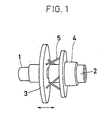
- This conventional device is not a torque sensor but has a specific structure in which, as shown in Fig. 1, a slide cylinder 3 on a main shaft 1 is coupled by springs 5 to a fixed sleeve 4 on a follower shaft 2. The rotation of the main shaft 1 causes the slide cylinder 3 to move axially to transmit an axial shift of the slide cylinder 3 to a spool (not shown).
- the respective springs 5 at an attitude inclined at 45 degrees at the neutral steering position change their attitude such that the respective springs gradually increase or otherwise decrease their inclination as the main shaft 1 rotates. Therefore, the quantity of axial shift of the slide cylinder 3 for unit angular rotation of the main shaft 1 varies depending upon the angle phase thereof. As a result, an unbalance occurs in the quantities of shift of the spool valve occurring when the steering wheel is rotated clockwise and counterclockwise, respectively. Therefore, if such an operating mechanism is applied to the torque sensor, the sensed torque value would vary depending on the direction of rotation of the main shaft even if the same torque may act on the main shaft.
- a slide cylinder is fitted axially slidably over one of the main shaft and follower shaft which are rotatable relative to each other on the same axis.
- a deviation sensor is provided for outputting a signal corresponding to a torque acting on the main shaft in response to an axial deviation of the slide cylinder.
- a first and a second connecting bodies are provided inclined in opposite directions in a plane parallel to the axis. The first and second connection bodies are connected at one end to the slide cylinder and at the other end to the main and follower shafts.
- the first and second connection bodies are inclined in an opposite direction maintaining the angle therebetween at a constant value in supplementary angle relationship. Therefore, the quantity of the axial deviation of the slide cylinder, namely, the output of the shift sensor, is free from an unbalance due to the direction of rotation to thereby achieve high-accuracy torque detection.
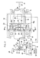
- reference numeral 10 denotes a housing for example, of a steering column of a vehicle.
- a main shaft 11 coupled to a steering wheel shaft and a follower shaft 12 coupled to an input shaft of the steering device are rotatably supported on the common rotational axis by bearing 13 and 14.
- the main shaft 11 is held by the follower shaft 12 such that a pair of sectral protrusions 11a formed on an end of the main shaft 11 are fitted loosely into a pair of corresponding sectral recesses 12a formed in the follower shaft 12.
- the central shaft 11b of the main shaft 11 is fitted into a hole 12b in the follower shaft 12 such that the main shaft is supported concentrically with the follower shaft 12.
- the sectral protrusions 11a and sectral recesses 12b allow a slight relative rotation between the main shaft 11 and follower shaft 12.
- a slide cylinder 16 is fitted around the main shaft 12 so as to rotate and slide axially.
- the slide cylinder 16 includes a flange portion 16b and a pair of jaws 16b, to each of which is integrally attached a first and a second connection bodies 18 and 19 by bolts 20.
- the bodies 18 and 19 are made of a spring material and extends swingable in a plane parallel to a plane which contains the width midpoint of the sectral protrusions 11a and the axis of rotation and are inclined relative to each other in opposite directions.
- the first connection body 18 is fixed integrally at one end by a fixing bolt 21 and a hold metal member 22 to the main shaft 11.
- the second connection body 19 is fixed integrally at one end to the follower shaft 12 by a fixing bolt 23 and a hold metal member 24. Therefore, by the rotation of the main shaft 11 relative to the follower shaft 12, the first and second connection bodies 18 and 19 are inclined in opposite directions from each other and an axial deviation corresponding to this inclination is applied to the slide cylinder 16.
- a deviation sensor 28 which senses an axial deviation of the slide cylinder 16 is connected to the flange 16a.
- the deviation sensor 28 is composed of a differential transformer which includes a well-known coil 28a and a core 28b.
- the core 28b and the flange 16a of the slide cylinder 16 are connected via a connection bar 30, so that an axial deviation of the slide cylinder 16 is sensed as an electric signal.
- the connection bar 30 has at one end a U-like member 30a which is allowed to rotate relative to the flange 16a only in the direction of the rotation of flange 16a.
- Reference numeral 31 denotes a torsion bar which connects the main and follower shafts 11 and 12 resiliently.
- the torsion bar 31 may be omitted using the spring rigidity of the first and second connection bodies 18 and 19.
- Reference numeral 33 denotes a needle bearing.
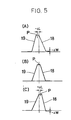
- the first connection body 18 is swung gradually in the direction in which the first connection body is inclined, while the second connection body 19 is swung in the direction in which the second connection body 19 rises, as shown in Fig. 5(A).
- the point P on the slide cylinder 16 coupled to the first and second connection bodies 18 and 19 deviates by ⁇ L in one direction, so that the quantity of deviation L is transduced into an electric signal by a deviation sensor 28 and output as a torque sensing signal.
- the first connection body 18 is swung in the direction in which the first connection body rises, while the second connection body 19 is swung in the direction in which the second connection body is inclined as shown in Fig. 5(C).
- the point P on the slide cylinder 16 coupled to the first and second connection bodies 18 and 19 deviates by ⁇ L in the + direction opposite to that mentioned above, so that the quantity of deviation ⁇ L is sensed as a torque sensing signal by the deviation sensor 28.
- Fig. 6 shows a deviation of the first and second connection bodies 18 and 19 occurring when the main shaft 11 is rotated clockwise or counterclockwise through a predetermined angle.
- the axial deviation quantities + ⁇ L and - ⁇ L of the point P are all L/2 - R x cos ( ⁇ + ⁇ ) and equal irrespective of clockwise or counterclockwise rotation, so that no unbalance occurs between quantities of axial deviation depending on the direction of rotation.
- a and B denote fixed points on the main shaft 11 and follower shaft 12 of the first and second connection bodies 18 and 19, respectively;
- L is the distance between the fixed points A and B; and R, the length of the first and second connection bodies 18 and 19;
- ⁇ is the angle of elevation of the point B obtained when the main shaft 11 is rotated by + - W;
- ⁇ is an angle formed by the first or second connection body 18 or 19 relative to the line segment A - B obtained when the main shaft is rotated by + - ⁇ W.
- first and second connection bodies 18 and 19 constitute the legs of an equilateral triangle whose base is defined by fixed points A and B and that the angle formed by the legs is kept constant even if the point P takes the position of any one of P1 and P2.
- first and second connection bodies 18 and 19 are provided with a phase difference of 180 degrees in the direction of rotation
- this invention is not limited to it.
- three or four sets of first and second connection bodies 18 and 19 may be provided with a phase difference of 120 degrees or 90 degrees, which serves to improve the support rigidity of the slide cylinder 16 to thereby prevent an inclination of the slide cylinder 16 and hence an increase in the sliding resistance thereof due to the inclination of the slide cylinder 16.
- first and second connection bodies 18 and 19 are made of a spring material, this invention is not limited to it.
- the first and second connection bodies may be constituted by links 18a and 19a which are not elastically deformed and pivoted to the drive shaft 11, follower shaft 12 and slide cylinder 16 by pivot pins 21a, 23a and 20a, respectively.
- the steering wheel shaft 40 with a steering wheel 41 is connected to the main shaft 11 of the torque sensor, while the input shaft 42 of the steering device is connected to the follower shaft 12 of the torque sensor.
- the input shaft 42 is rotatably carried by a gear box 43 and is formed with a pinion 44 which meshes with a rack 45 axially slidably received in the gear box 43.
- opposite ends of the rack 45 are connected to steerable front wheels 46 through ball joints and the like, as is well known in the art.
- the input shaft 42 is drivingly coupled through a pair of gears 47 to an electric motor 48 which generates an assisting power.
- a voltage VE from a d.c. generator or dynamo 51 drivingly connected to the automotive engine (not shown) is generated upon rotation of the engine and is applied to the electric motor 48 through a control circuit 52.
- the circuit 52 receives a steering effort signal Tm from the aforementioned deviation sensor 28 of the torque sensor, a vehicle speed signal (V) from a vehicle speed sensor 53 and a load current Id from the electric motor 48.
- the circuit 52 controls an input voltage VEO to the electric motor 48 so that when the vehicle speed V is within a low speed range (e.g., less than 60 km/h), the assisting power generated by the electric motor 48 is nonlinearly varied with the variation in the steering effort Tm in such a manner as to make the increasing rate of the assisting power larger as the vehicle speed V decreases and so that when the vehicle speed V is within a high speed range (e.g., 60 km/h or more), the assisting power is linearly varied with variation in the steering effort Tm in such a manner as to make the increasing rate of the assisting power smaller as the vehicle speed V increases.
- a low speed range e.g., less than 60 km/h
- the assisting power generated by the electric motor 48 is nonlinearly varied with the variation in the steering effort Tm in such a manner as to make the increasing rate of the assisting power larger as the vehicle speed V decreases and so that when the vehicle speed V is within a high speed range (e.g., 60 km/h or
- the sectral protrusions 11a and sectral recesses 12b of the torque sensor as described above limits the relative rotation between the main shaft 11 and the follower shaft 12 to several degrees of angle in either direction.
- the connection bodies 18, 19 or the links 18a, 19a are broken, the steering effort applied to the steering wheel 41 can be reliably transmitted to the input shaft 42 of the power steering device.
- a torque sensor in which a main shaft and a follower shaft are supported rotatably relative to each other on a common axis.
- a sleeve is supported axially slidable on one of the main and follower shafts.
- a deviation sensor is responsive to an axial movement of the sleeve to output a signal corresponding to the quantity of the axial movement.
- At least one set of torque transmitting members is provided to transmit the torque applied to the main shaft to the follower shaft and to move the sleeve axially in accordance with the torque.
- the at least one set of torque transmitting members comprises a first connection body extending parallel to the common axis, inclined in a plane offset radially of the main and follower shafts, and connected at one and the other ends to the sleeve and main shaft, respectively. It also includes a second connection body provided inclined in the plane and in the opposite direction to that in which the first connection body is inclined, and connected at one and the other ends to the sleeve and the follower shaft, respectively.
Landscapes
- Engineering & Computer Science (AREA)
- Physics & Mathematics (AREA)
- General Physics & Mathematics (AREA)
- Chemical & Material Sciences (AREA)
- Combustion & Propulsion (AREA)
- Transportation (AREA)
- Mechanical Engineering (AREA)
- Force Measurement Appropriate To Specific Purposes (AREA)
- Power Steering Mechanism (AREA)
Applications Claiming Priority (2)
| Application Number | Priority Date | Filing Date | Title |
|---|---|---|---|
| JP72851/87 | 1987-03-26 | ||
| JP62072851A JPS63238439A (ja) | 1987-03-26 | 1987-03-26 | トルクセンサ |
Publications (2)
| Publication Number | Publication Date |
|---|---|
| EP0283691A2 true EP0283691A2 (fr) | 1988-09-28 |
| EP0283691A3 EP0283691A3 (fr) | 1989-10-18 |
Family
ID=13501290
Family Applications (1)
| Application Number | Title | Priority Date | Filing Date |
|---|---|---|---|
| EP88101893A Ceased EP0283691A3 (fr) | 1987-03-26 | 1988-02-09 | Capteur de couple |
Country Status (3)
| Country | Link |
|---|---|
| US (1) | US4864873A (fr) |
| EP (1) | EP0283691A3 (fr) |
| JP (1) | JPS63238439A (fr) |
Cited By (3)
| Publication number | Priority date | Publication date | Assignee | Title |
|---|---|---|---|---|
| EP0978713A3 (fr) * | 1998-08-03 | 2001-08-08 | Mannesmann VDO Aktiengesellschaft | Limitation angulaire par joint de séparation dans la boíte d'un capteur de couple |
| FR2909760A1 (fr) * | 2006-12-07 | 2008-06-13 | Peugeot Citroen Automobiles Sa | Dispositif de mesure d'un couple de torsion et ensemble forme d'un arbre tournant et d'un dispositif de mesure du couple de torsion |
| CN113720511A (zh) * | 2021-08-31 | 2021-11-30 | 浙江清华柔性电子技术研究院 | 轴系配合监测装置 |
Families Citing this family (3)
| Publication number | Priority date | Publication date | Assignee | Title |
|---|---|---|---|---|
| GB2255183A (en) * | 1991-04-15 | 1992-10-28 | David Alick Burgoyne | Torque sensor |
| DE19831739A1 (de) * | 1998-07-15 | 2000-01-20 | Mannesmann Vdo Ag | Schneckengetriebe mit Elektromotor |
| DE102008018362A1 (de) * | 2008-04-11 | 2009-10-15 | Liebherr-Aerospace Lindenberg Gmbh | Drehmomentsensor |
Family Cites Families (11)
| Publication number | Priority date | Publication date | Assignee | Title |
|---|---|---|---|---|
| US2260036A (en) * | 1940-08-24 | 1941-10-21 | Gen Electric | Transmission dynamometer |
| US2964017A (en) * | 1957-12-09 | 1960-12-13 | Bendix Corp | Power steering mechanism |
| US3823608A (en) * | 1972-10-25 | 1974-07-16 | Southern Gas Ass | Torque transducer |
| SU466414A2 (ru) * | 1972-12-11 | 1975-04-05 | Украинский научно-исследовательский институт механизации и электрификации сельского хозяйства | Измеритель мощности на валу |
| JPS5870136A (ja) * | 1981-10-22 | 1983-04-26 | Mitsubishi Electric Corp | トルク検出器 |
| JPS5932835A (ja) * | 1982-08-17 | 1984-02-22 | Komatsu Ltd | トルクセンサ |
| FR2576573B1 (fr) * | 1985-01-29 | 1989-12-08 | Peugeot | Direction assistee hydraulique pour vehicule automobile |
| US4584884A (en) * | 1985-03-22 | 1986-04-29 | Lesko Gerald J | Torque sensor |
| JPH0662093B2 (ja) * | 1985-03-29 | 1994-08-17 | 豊田工機株式会社 | 電気式動力舵取装置 |
| US4724711A (en) * | 1985-09-03 | 1988-02-16 | Aisin Seiki Kabushiki Kaisha | Torque detector |
| JPH0798490B2 (ja) * | 1986-02-06 | 1995-10-25 | 本田技研工業株式会社 | 電動式パワーステアリング装置 |
-
1987
- 1987-03-26 JP JP62072851A patent/JPS63238439A/ja active Pending
-
1988
- 1988-02-09 EP EP88101893A patent/EP0283691A3/fr not_active Ceased
- 1988-02-16 US US07/155,873 patent/US4864873A/en not_active Expired - Fee Related
Cited By (4)
| Publication number | Priority date | Publication date | Assignee | Title |
|---|---|---|---|---|
| EP0978713A3 (fr) * | 1998-08-03 | 2001-08-08 | Mannesmann VDO Aktiengesellschaft | Limitation angulaire par joint de séparation dans la boíte d'un capteur de couple |
| FR2909760A1 (fr) * | 2006-12-07 | 2008-06-13 | Peugeot Citroen Automobiles Sa | Dispositif de mesure d'un couple de torsion et ensemble forme d'un arbre tournant et d'un dispositif de mesure du couple de torsion |
| CN113720511A (zh) * | 2021-08-31 | 2021-11-30 | 浙江清华柔性电子技术研究院 | 轴系配合监测装置 |
| CN113720511B (zh) * | 2021-08-31 | 2023-10-20 | 浙江清华柔性电子技术研究院 | 轴系配合监测装置 |
Also Published As
| Publication number | Publication date |
|---|---|
| EP0283691A3 (fr) | 1989-10-18 |
| US4864873A (en) | 1989-09-12 |
| JPS63238439A (ja) | 1988-10-04 |
Similar Documents
| Publication | Publication Date | Title |
|---|---|---|
| EP0186053B1 (fr) | Détecteur de couple pour direction assistée électrique | |
| US5174407A (en) | Variable ratio steering system | |
| EP1288106A2 (fr) | Direction assistée électrique avec système anti-vol et son procédé de fabrication | |
| GB2274818A (en) | Variable ratio steering system. | |
| US4853672A (en) | Steering angle detector | |
| US5386879A (en) | Steering angle ratio varying device for a vehicle | |
| JP2000310574A (ja) | トルク感知装置 | |
| JPS63192656A (ja) | 電気式パワ−ステアリング装置の操舵トルク検出装置 | |
| US4864873A (en) | Torque sensor | |
| US4671372A (en) | Motor-driven power steering unit | |
| EP0205812B1 (fr) | Accouplement d'un transducteur de couple | |
| US4800764A (en) | Apparatus for sensing relative rotation between members | |
| GB2161030A (en) | Electromagnetic servo unit | |
| EP0174202B1 (fr) | Appareil de direction assistée | |
| US4548091A (en) | Motion converter for use in transducers and the like | |
| EP0728653B1 (fr) | Direction assistée électrique | |
| US20250263109A1 (en) | Vehicle steering apparatus and vehicle including same | |
| JPH06298Y2 (ja) | 電動式動力かじ取装置 | |
| JP2567227Y2 (ja) | 電動パワーステアリング装置 | |
| JPH0546549Y2 (fr) | ||
| JPH0616855Y2 (ja) | 電動式動力かじ取装置 | |
| JP3355221B2 (ja) | 電動式後輪操舵装置 | |
| JPH0352607Y2 (fr) | ||
| JPH0616854Y2 (ja) | 電動式動力かじ取装置 | |
| JP2617736B2 (ja) | 電動パワーステアリング装置 |
Legal Events
| Date | Code | Title | Description |
|---|---|---|---|
| PUAI | Public reference made under article 153(3) epc to a published international application that has entered the european phase |
Free format text: ORIGINAL CODE: 0009012 |
|
| AK | Designated contracting states |
Kind code of ref document: A2 Designated state(s): DE FR GB |
|
| PUAL | Search report despatched |
Free format text: ORIGINAL CODE: 0009013 |
|
| AK | Designated contracting states |
Kind code of ref document: A3 Designated state(s): DE FR GB |
|
| 17P | Request for examination filed |
Effective date: 19900329 |
|
| 17Q | First examination report despatched |
Effective date: 19920331 |
|
| STAA | Information on the status of an ep patent application or granted ep patent |
Free format text: STATUS: THE APPLICATION HAS BEEN REFUSED |
|
| 18R | Application refused |
Effective date: 19921026 |