EP0283704A2 - Dispositif de mesure, en particulier balance,avec dispositif de sortie et plaque d'identification - Google Patents
Dispositif de mesure, en particulier balance,avec dispositif de sortie et plaque d'identification Download PDFInfo
- Publication number
- EP0283704A2 EP0283704A2 EP19880102090 EP88102090A EP0283704A2 EP 0283704 A2 EP0283704 A2 EP 0283704A2 EP 19880102090 EP19880102090 EP 19880102090 EP 88102090 A EP88102090 A EP 88102090A EP 0283704 A2 EP0283704 A2 EP 0283704A2
- Authority
- EP
- European Patent Office
- Prior art keywords
- sensor
- output device
- identification plate
- measuring device
- signal line
- Prior art date
- Legal status (The legal status is an assumption and is not a legal conclusion. Google has not performed a legal analysis and makes no representation as to the accuracy of the status listed.)
- Granted
Links
Images
Classifications
-
- G—PHYSICS
- G01—MEASURING; TESTING
- G01G—WEIGHING
- G01G23/00—Auxiliary devices for weighing apparatus
- G01G23/01—Testing or calibrating of weighing apparatus
- G01G23/017—Securing calibration against fraud
-
- G—PHYSICS
- G01—MEASURING; TESTING
- G01D—MEASURING NOT SPECIALLY ADAPTED FOR A SPECIFIC VARIABLE; ARRANGEMENTS FOR MEASURING TWO OR MORE VARIABLES NOT COVERED IN A SINGLE OTHER SUBCLASS; TARIFF METERING APPARATUS; MEASURING OR TESTING NOT OTHERWISE PROVIDED FOR
- G01D18/00—Testing or calibrating apparatus or arrangements provided for in groups G01D1/00 - G01D15/00
-
- G—PHYSICS
- G01—MEASURING; TESTING
- G01G—WEIGHING
- G01G23/00—Auxiliary devices for weighing apparatus
- G01G23/18—Indicating devices, e.g. for remote indication; Recording devices; Scales, e.g. graduated
- G01G23/36—Indicating the weight by electrical means, e.g. using photoelectric cells
Definitions
- the invention relates to a measuring device, in particular a scale, with a sensor, the output signal of which is a digital value directly representing the measured value and its unit of measurement, an output device for the measured value which is locally separated from the sensor and has a visual display, and which is connected to the sensor by a signal line is connected and a label serving as a carrier of the measurement data of the sensor.
- the identification plate showing the measurement data is arranged in the vicinity of the display indicating the measured value.
- the identification plate showing the measurement data includes, for example, a scale the metrological data information about the maximum load, the division, the tare range u.
- the connection between the sensor and the output device which is only established by the signal line, must not be solved in the known measuring devices. If detachable couplings are provided between the signal line and the sensor or the signal line and the output device, these couplings are therefore secured with seals in the known measuring devices, these seals being destroyed when separated.
- the invention has for its object to design a measuring device, in particular a balance of the type mentioned in such a way that the sensor or the output device can be replaced without having to re-calibrate the entire measuring device.
- the identification plate is detachably arranged on the output device and is inseparably connected to the sensor by a connecting member.
- the output device can thus be separated from the sensor without the connection between the identification plate which is decisive for the calibration and the calibrated sensor being lost. Nevertheless, the label does not have to be arranged on the sensor itself, but is located on the locally separate output device and thus in the vicinity of the visual display showing the measured value.
- a particularly expedient embodiment of the invention consists in that the connecting element is formed by the signal line that is inseparably connected to the sensor, with the end facing the output device that the identification plate is inseparably connected.
- the signal line which is required anyway is used as a connecting link, which results in a very simple construction.
- the signal line is passed through a hole in the identification plate, the diameter of which is larger than the outside diameter of the signal line but smaller than the end of the signal line which is detachably coupled to the output device.
- This embodiment enables particularly simple handling because the identification label can be moved on the signal line and can therefore be removed particularly easily from the output device.
- the end of the signal line that is thickened in relation to the hole in the identification plate ensures that the identification plate is caught on the signal line and thus remains inseparably connected to the sensor.
- the senor has a non-volatile memory for a code number representing a code value for the valid calibration of the sensor, as well as one for automatically advancing the code number by a certain unit for each recalibration and for storing this forwarded code number as new code value in the non-volatile submission serving, and that a letter provided with the applicable code is arranged on the label and secured there with a seal. If, therefore, the sensor is subjected to a recalibration, for example an adjustment of its sensitivity or its unit of measure, which can be done, for example, by control commands entered from the output device via the signal line, the key figure representing the previously valid calibration is automatically switched on and stored.
- a recalibration for example an adjustment of its sensitivity or its unit of measure
- the writing medium is formed by a disk rotatably mounted on a surface area of the identification plate, which is provided in the azimuthal direction with a sequence of the possible identification numbers, of which only the respectively applicable one is indicated by a window of the label is visible through, and that the rotational position of the disc in relation to the window is determined by the seal.
- the disk after the new calibration, only the disk has to be rotated until the relevant identification number appears in the window of the identification label and the new seal has to be attached in this position.
- the measuring data of the sensor are arranged on a writing medium, which is also secured by the seal on the identification plate. These measures make it easy to replace the writing medium with a new writing medium which bears the measurement data of the sensor on which the new calibration is based.
- the seal which is to be installed in the new calibration anyway, ensures that the writing medium cannot be replaced without being noticed.
- a particularly useful further embodiment of this embodiment is that the writing medium for the metrological data of the sensor is arranged between the output device and the identification plate which is in positive engagement with the output device and which is transparent in the area of the writing medium.
- the writing medium is simply positively clamped between the identification plate and the corresponding contact surface of the output device and is visible through the transparent area of the identification plate and protected at the same time.
- the invention also extends to the idea that the identification plate has an electrical scanning device for the valid code number of the writing medium and that the output device has a comparison device for the scanned code and the code number stored in the sensor, which blocks the measured value output if they do not match. These measures automatically shut the measuring device down when there is no longer a valid calibration.
- the output device has a visual display for the characteristic number stored in the sensor.
- An optical comparison between the code displayed on the output device and the code set on the label can be used to determine at any time whether there is still a match, i.e. there is a valid calibration.
- the arrangement of the identification plate on the output device can be done particularly simply in that the identification plate has locking projections with which it is releasably locked on the output device.
- the identification plate has a magnet arrangement which serves for an adhesive connection to the output device. So in both cases it is possible to detach the identification plate by a simple pull by hand from the output device, the latter then being able to be handled separately from the sensor after the coupling between the signal line and the output device has been released.
- the output device can be easily replaced without destroying the calibration that applies to the sensor.
- the sensor can also be replaced by another sensor that has already been calibrated.
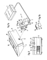
- a sensor 1 is provided in a weighing platform, not shown, by means of which the weight of a load placed on the weighing platform 1 is detected and converted into a measured value corresponding to the weight of the load.
- the sensor 1 is constructed in such a way that its output signal forms a digital value directly representing the measured value, that is to say the weight value, and its unit of measurement.
- the output signal of sensor 1 therefore does not require any evaluating Processing more, but can be displayed immediately to reproduce the weight value.
- a signal line 2 is inseparably connected to the sensor 1, on which the output signal of the sensor 1 is fed to an output device 3 which is locally separated therefrom.
- a display 4 provided in the output device 3 serves for the visual representation of the weight value and its unit of measure.
- the signal line 2 forming the only connecting link between the sensor 1 and the output device 3 is inseparably connected to the sensor at its end located at the sensor 1, its other end facing the output device 3 forms the one coupling part 5 of a plug-in coupling, the complementary coupling part 6 thereof is arranged on the output device 3.
- the coupling formed from the coupling parts 5 and 6 the connection between the output device 3 and the weighing platform 1 can thus be separated, as shown in FIG. 1a.
- the free end region 12 of the leg 11 is provided with a bore 13, the diameter of which is slightly larger than the outer diameter of the signal line 2 passed through the bore 13. In contrast, the diameter of the bore 13 is smaller than the end coupling part 5 which can be coupled to the output device 3 Signal line 2.
- the label 7 on the Signal line 2 caught and thereby inseparably connected to the sensor 1 of the weighing platform.
- the identification plate 7 is positively connected to the output device 3 by means of a locking bar 14 provided at the free end of the leg 9, which engages in a locking recess 15 of the output device 3, so it is possible to loosen it the locking connection and by separating the coupling parts 5, 6 to separate the weighing platform containing the sensor 1 together with the identification plate 7 in the manner shown in FIG. 1a from the output device 3.
- the sensor 1 provided in the weighing platform is also constructed in such a way that recalibrations of the sensor, such as changes in the sensitivity or the unit of measurement or auto-calibrations, are triggered by control signals supplied via the signal line 2.
- the output device 3 is provided with a keyboard 16, via which corresponding control commands can be entered.
- the sensor 1 has a non-volatile memory in which a characteristic number representing a code value for the valid calibration of the sensor is stored. This memory can be formed, for example, by an EAROM.
- a logic device further provided in sensor 1 switches this key figure forward by a certain unit in response to each command for recalibration and stores this key figure as a new code value in the non-volatile memory. This key figure forming the new code value can be displayed either permanently or after being called up by a specific key on the keyboard 16 on the output device 3, for example on the visual display 4.
- a disk 17 is rotatably mounted, on which, along a circumferential circle concentric with the rotary bearing 18, a sequence of identification numbers corresponding to the sequence of the possible identification numbers of the sensor at equal angular distances is arranged.
- the leg 11 of the identification plate 7 has a window 19 at a radial distance from the rotary bearing 18, which corresponds to the radial distance of the characteristic numbers, through which a respective number of the angle formed by the disk 17 on the inside of the angle device facing the output device 3 passes Identification label 7 arranged writer is visible.
- the disk 17 has bores at an angular distance corresponding to the angular distance of the key figures, one of which is aligned with a bore 20 of the leg 11 when a corresponding key number is just in register with the window 19.
- the diameter of these bores allows the wire of a seal 21 to pass through, through which the disk 17 is sealed in its rotational position in relation to the window 19.
- the relevant metrological data change which is on the identification plate 7 in the vicinity of the visual display 4 are to be shown.
- a cross-sectionally L-shaped, further writing medium 22, shown in FIG. 1b is provided, the one L-leg 23, labeled with the relevant measurement data, extends along the inner surface of the leg 9 of the identification plate 7, which lies against the output device 3, while its other L-leg 24 extends along the leg 11 provided with the bore 20 of the identification plate 7.
- a congruent bore 25 is provided with the bore 20 of the identification plate 7, which is also penetrated by the wire of the seal 21, whereby the writing medium 22 by means of the seal 21 on the identification plate 7 and thus with regard to its relationship with the sensor 1 of the weighing platform is secured.
- the L-leg 24 can have a further recess 26 in the region of the pivot bearing 18.
- the leg 9 of the identification plate 7 is transparent, so that in the state of the identification plate 7 shown in FIG. 2, snapped onto the output device 3, the measurement data printed on the L-leg 23 of the document clamped between the output device and the inside of the identification plate 7 22 through the leg 9 are visible.
- a magnet arrangement can also be provided, for example, by means of which the identification plate 7 is held on the output device 3 by means of magnetic force.
- the identification plate 7 can also be assigned an electrical scanning device for the valid identification number set in the window 19, although this is not shown in FIG. 1a. If, for example, the disk 17 is provided with the sequence of numbers from 1 to 16, four concentric tracks can be arranged on it, according to a predetermined code pattern are alternately composed of electrically conductive and non-conductive layers. These tracks are each electrically sensed with a sliding contact, as a result of which a unique 4-bit code is recorded for each applicable code number set in window 19. This detection signal is compared by a comparison device provided in the output device 3 with the characteristic number stored in the sensor 1. If they do not match, the measured value output of the output device 3 is then blocked.
- the coupling 5, 6 can be released and the identification label 7 can be removed from the output device 3 and another output device can be connected.
- the sensor 1 provided in the weighing platform has not changed its calibration status as a result, so that re-calibration is not necessary.
- a new pre-calibrated sensor 1 which is provided with the signal line 2, the identification plate 7 and the seal number set and sealed thereon, can be connected to the evaluation device 3. This means that the entire scale remains ready for operation without the need to re-calibrate the entire scale.
Landscapes
- Physics & Mathematics (AREA)
- General Physics & Mathematics (AREA)
- Arrangements For Transmission Of Measured Signals (AREA)
- Measurement Of Length, Angles, Or The Like Using Electric Or Magnetic Means (AREA)
- Transmission And Conversion Of Sensor Element Output (AREA)
- Length Measuring Devices With Unspecified Measuring Means (AREA)
- Measurement Of Radiation (AREA)
- Pens And Brushes (AREA)
- Measuring Pulse, Heart Rate, Blood Pressure Or Blood Flow (AREA)
Applications Claiming Priority (2)
| Application Number | Priority Date | Filing Date | Title |
|---|---|---|---|
| DE3709717A DE3709717C2 (de) | 1987-03-25 | 1987-03-25 | Meßgerät, insbesondere Waage |
| DE3709717 | 1987-03-25 |
Publications (3)
| Publication Number | Publication Date |
|---|---|
| EP0283704A2 true EP0283704A2 (fr) | 1988-09-28 |
| EP0283704A3 EP0283704A3 (en) | 1989-08-09 |
| EP0283704B1 EP0283704B1 (fr) | 1991-09-18 |
Family
ID=6323891
Family Applications (1)
| Application Number | Title | Priority Date | Filing Date |
|---|---|---|---|
| EP88102090A Expired - Lifetime EP0283704B1 (fr) | 1987-03-25 | 1988-02-12 | Dispositif de mesure, en particulier balance,avec dispositif de sortie et plaque d'identification |
Country Status (4)
| Country | Link |
|---|---|
| US (1) | US4799559A (fr) |
| EP (1) | EP0283704B1 (fr) |
| JP (2) | JPS63266317A (fr) |
| DE (1) | DE3709717C2 (fr) |
Cited By (3)
| Publication number | Priority date | Publication date | Assignee | Title |
|---|---|---|---|---|
| FR2718525A1 (fr) * | 1994-04-08 | 1995-10-13 | Klotz Antoine | Système de sécurité associé à un appareil nécessitant une intervention suivant un calendrier prédéterminé. |
| EP0911618A1 (fr) * | 1997-10-27 | 1999-04-28 | Bizerba GmbH & Co. KG | Balance électronique avec dispositif de sécurité calibrée automatiquement |
| WO2007124834A3 (fr) * | 2006-04-28 | 2008-12-31 | Conducta Endress & Hauser | Procédé d'étalonnage et/ou de réglage d'un capteur, notamment d'un capteur électrochimique, électrophysique ou optique, ainsi que capteur correspondant |
Families Citing this family (14)
| Publication number | Priority date | Publication date | Assignee | Title |
|---|---|---|---|---|
| DE9420378U1 (de) * | 1994-02-04 | 1995-06-01 | Sartorius AG, 37075 Göttingen | Anlage zur Meßwerterfassung und Anzeige, insbesondere Wägeanlage |
| US5841077A (en) * | 1995-12-01 | 1998-11-24 | Kolaci; Rudolph J. | Digital load cell assembly |
| US6194671B1 (en) * | 1999-05-03 | 2001-02-27 | Vaghi Family Intellectual Properties, Llc | Electronic scale |
| JP4523686B2 (ja) * | 1999-11-09 | 2010-08-11 | 株式会社エー・アンド・デイ | 電子部と機構部とが各々独立している電子秤 |
| US6376783B1 (en) * | 2000-05-31 | 2002-04-23 | Vaghi Family Intellectual Properties, Llc | Removable electronic scale cartridge, and a system and method which uses the scale cartridge to compute postal/carrier rates |
| US6315470B1 (en) | 2000-09-20 | 2001-11-13 | National Mailing Systems | Personal computer having a built-in printer, and a system and method for computing rate information using the computer |
| DE10357856B4 (de) * | 2003-12-11 | 2008-01-03 | Sartorius Ag | Messvorrichtung |
| US20090205876A1 (en) * | 2008-02-19 | 2009-08-20 | Rubbermaid Incorporated | Digital Scale with Magnetic Engagement of a User Interface Unit |
| EP2416130B1 (fr) * | 2010-08-05 | 2013-06-12 | Mettler-Toledo (Albstadt) GmbH | Appareil, notamment balance dotée d'éléments d'étalonnage |
| US9255859B2 (en) | 2010-11-15 | 2016-02-09 | Advanced Mechanical Technology, Inc. | Force platform system |
| US8978181B2 (en) | 2012-03-21 | 2015-03-17 | Midmark Corporation | Medical examination table with integrated scale |
| US10682082B2 (en) * | 2015-06-30 | 2020-06-16 | Koninklijke Philips N.V. | Sensor system and method which makes use of multiple PPG sensors |
| DE102017104367A1 (de) * | 2017-03-02 | 2018-09-06 | Bizerba SE & Co. KG | Wägezelle für eine Waage |
| EP3425324B2 (fr) * | 2017-07-04 | 2022-11-16 | Sick Ag | Procédé de paramétrage d'un capteur |
Family Cites Families (14)
| Publication number | Priority date | Publication date | Assignee | Title |
|---|---|---|---|---|
| DE2904261C2 (de) * | 1979-02-05 | 1989-01-12 | Maatschappij van Berkel's, Patent N.V., Rotterdam | Elektronische Waage, insb. Ladenwaage |
| DE2922875A1 (de) * | 1979-06-06 | 1980-12-18 | Sartorius Gmbh | Elektrische waage mit programmgesteuertem mikroprozessor |
| JPS56125631A (en) * | 1980-03-06 | 1981-10-02 | Kubota Ltd | Span adjusting method |
| US4377214A (en) * | 1981-02-10 | 1983-03-22 | Pitney Bowes, Inc. | Method and apparatus for interfacing an electronic scale system with a storage medium |
| US4423486A (en) * | 1981-04-30 | 1983-12-27 | Hobart Corporation | Commodity display for weighing scale |
| DE3129408A1 (de) * | 1981-07-25 | 1983-03-03 | DSG Schrumpfschlauch GmbH, 5309 Meckenheim | Kennzeichentraeger aus kunststoff zum kennzeichnen von gegenstaenden, wie geraete, kabel, leitungen, rohre, schlaeuche oder dergleichen |
| US4506330A (en) * | 1982-07-06 | 1985-03-19 | Pitney Bowes Inc. | Electronic mailing apparatus and method |
| US4597457A (en) * | 1982-08-19 | 1986-07-01 | Kabushiki Kaisha Ishida Koki Seisakusho | Electronic scale with CRT display |
| CH656463A5 (en) * | 1982-09-30 | 1986-06-30 | Mettler Instrumente Ag | Balance |
| CH659890A5 (de) * | 1983-01-29 | 1987-02-27 | Mettler Instrumente Ag | Messgeraet mit einem durch einlesen einer vorgegebenen elektrischen impulsfolge programmierbaren nichtfluechtigen schreib-/lesespeicher. |
| JPH0695039B2 (ja) * | 1983-01-31 | 1994-11-24 | 株式会社寺岡精工 | 計量装置 |
| JPS6042932U (ja) * | 1983-08-31 | 1985-03-26 | 株式会社 石田衡器製作所 | 電子秤 |
| DE3407463A1 (de) * | 1984-02-29 | 1985-08-29 | August Sauter Gmbh, 7470 Albstadt | Messgeraet, insbesondere waage, mit selbsttaetiger betriebsartumschaltung (modeumschaltung) |
| DE3447287A1 (de) * | 1984-12-24 | 1986-07-10 | Idento - Gesellschaft für industrielle Kennzeichnung mbH, 6074 Rödermark | Kennzeichnungsschild fuer kabel, rohre, behaelter u.dgl. |
-
1987
- 1987-03-25 DE DE3709717A patent/DE3709717C2/de not_active Expired - Lifetime
-
1988
- 1988-02-12 EP EP88102090A patent/EP0283704B1/fr not_active Expired - Lifetime
- 1988-03-24 JP JP63068357A patent/JPS63266317A/ja active Pending
- 1988-03-24 US US07/172,442 patent/US4799559A/en not_active Expired - Lifetime
-
1995
- 1995-01-13 JP JP000066U patent/JPH0743684U/ja active Pending
Cited By (5)
| Publication number | Priority date | Publication date | Assignee | Title |
|---|---|---|---|---|
| FR2718525A1 (fr) * | 1994-04-08 | 1995-10-13 | Klotz Antoine | Système de sécurité associé à un appareil nécessitant une intervention suivant un calendrier prédéterminé. |
| EP0911618A1 (fr) * | 1997-10-27 | 1999-04-28 | Bizerba GmbH & Co. KG | Balance électronique avec dispositif de sécurité calibrée automatiquement |
| WO2007124834A3 (fr) * | 2006-04-28 | 2008-12-31 | Conducta Endress & Hauser | Procédé d'étalonnage et/ou de réglage d'un capteur, notamment d'un capteur électrochimique, électrophysique ou optique, ainsi que capteur correspondant |
| US8733148B2 (en) | 2006-04-28 | 2014-05-27 | Endress + Hauser Conducta Gesellschaft für Mess- und Regeltechnik mbH + Co. KG | Method for calibrating and/or adjusting a sensor, especially an electrochemical, electrophysical or optical sensor, and corresponding sensor |
| EP2024711B1 (fr) | 2006-04-28 | 2016-11-02 | Endress + Hauser Conducta GmbH + Co. KG | Procédé d'étalonnage et/ou de réglage d'un capteur |
Also Published As
| Publication number | Publication date |
|---|---|
| DE3709717A1 (de) | 1988-10-06 |
| JPH0743684U (ja) | 1995-09-05 |
| JPS63266317A (ja) | 1988-11-02 |
| US4799559A (en) | 1989-01-24 |
| EP0283704B1 (fr) | 1991-09-18 |
| EP0283704A3 (en) | 1989-08-09 |
| DE3709717C2 (de) | 1997-05-15 |
Similar Documents
| Publication | Publication Date | Title |
|---|---|---|
| EP0283704B1 (fr) | Dispositif de mesure, en particulier balance,avec dispositif de sortie et plaque d'identification | |
| DE3841252C2 (de) | Codiervorrichtung | |
| DE2259731A1 (de) | Kodierte aufschrift zur automatischen identifizierung von gegenstaenden | |
| DE7421453U (de) | Vorrichtung zum messen des den lasthaken eines krans belastenden gewichts | |
| EP0194477A1 (fr) | Dispositif de balayage à rayons X | |
| DE3432511C2 (fr) | ||
| DE19817953A1 (de) | Markiervorrichtung | |
| DE4229610A1 (de) | Drehgeber mit absolutwert-positionserfassung | |
| DE2652309B2 (de) | Wandler zum Umwandeln mechanischer Kräfte in elektrische Signale | |
| DE10348887A1 (de) | Tastkopf für ein Koordinatenmessgerät | |
| EP0550794B1 (fr) | Codeur de rotation avec détection de valeur absolue de position | |
| DE2929168C2 (de) | Vorrichtung zum Erfassen, Speichern und ggf. Auswerten von Fahrdaten | |
| EP1321743B1 (fr) | Système pour mesurer une longueur absolue comprenant une barre de mesure qui se déplace relativement par rapport à des sondes de longueur mutuellement espacées | |
| DE112008002382T5 (de) | Auswechselbare Hebelanordnungen | |
| DE10390447T5 (de) | Digitaler Sensor | |
| DE3123572C2 (de) | Meßsystem zum berührungslosen Erfassen von Kolbenstangenpositionen | |
| DE102005055905A1 (de) | Längenmessanordnung mit einem magnetischen Maßstab mit gegenläufiger Magnetisierung | |
| DD159211A1 (de) | Anordnung zur lagebestimmung eines index gegenueber einer teilung | |
| DE3841216A1 (de) | Druckrad-anordnung mit codiervorrichtung | |
| EP4042112B1 (fr) | Système de mesure | |
| DE4317084A1 (de) | Unterdruck-Sicherheitsventil | |
| AT526540A1 (de) | Vorrichtung zur Messung eines absoluten Drehwinkels eines drehbar gelagerten Elements | |
| EP0072369B1 (fr) | Imprimante du ruban acier à identification automatique du ruban imprimeur | |
| DE3147172A1 (de) | Riegelelement mit einem in einer huelse zwischen zwei endlagen gefuehrten verriegelungszapfen | |
| EP4365719A2 (fr) | Procédé de lecture d'informations à partir d'un champ de codage mono ou multidimensionnel |
Legal Events
| Date | Code | Title | Description |
|---|---|---|---|
| PUAI | Public reference made under article 153(3) epc to a published international application that has entered the european phase |
Free format text: ORIGINAL CODE: 0009012 |
|
| AK | Designated contracting states |
Kind code of ref document: A2 Designated state(s): CH FR GB IT LI NL |
|
| ITCL | It: translation for ep claims filed |
Representative=s name: JACOBACCI CASETTA & PERANI S.P.A. |
|
| TCNL | Nl: translation of patent claims filed | ||
| GBC | Gb: translation of claims filed (gb section 78(7)/1977) | ||
| EL | Fr: translation of claims filed | ||
| PUAL | Search report despatched |
Free format text: ORIGINAL CODE: 0009013 |
|
| AK | Designated contracting states |
Kind code of ref document: A3 Designated state(s): CH FR GB IT LI NL |
|
| 17P | Request for examination filed |
Effective date: 19891220 |
|
| RAP3 | Party data changed (applicant data changed or rights of an application transferred) |
Owner name: METTLER-TOLEDO (ALBSTADT) GMBH |
|
| 17Q | First examination report despatched |
Effective date: 19901220 |
|
| GRAA | (expected) grant |
Free format text: ORIGINAL CODE: 0009210 |
|
| AK | Designated contracting states |
Kind code of ref document: B1 Designated state(s): CH FR GB IT LI NL |
|
| ITF | It: translation for a ep patent filed | ||
| GBT | Gb: translation of ep patent filed (gb section 77(6)(a)/1977) | ||
| ET | Fr: translation filed | ||
| PLBE | No opposition filed within time limit |
Free format text: ORIGINAL CODE: 0009261 |
|
| STAA | Information on the status of an ep patent application or granted ep patent |
Free format text: STATUS: NO OPPOSITION FILED WITHIN TIME LIMIT |
|
| 26N | No opposition filed | ||
| REG | Reference to a national code |
Ref country code: GB Ref legal event code: IF02 |
|
| PGFP | Annual fee paid to national office [announced via postgrant information from national office to epo] |
Ref country code: NL Payment date: 20070213 Year of fee payment: 20 |
|
| PGFP | Annual fee paid to national office [announced via postgrant information from national office to epo] |
Ref country code: CH Payment date: 20070214 Year of fee payment: 20 |
|
| PGFP | Annual fee paid to national office [announced via postgrant information from national office to epo] |
Ref country code: GB Payment date: 20070216 Year of fee payment: 20 |
|
| PGFP | Annual fee paid to national office [announced via postgrant information from national office to epo] |
Ref country code: IT Payment date: 20070626 Year of fee payment: 20 |
|
| REG | Reference to a national code |
Ref country code: GB Ref legal event code: PE20 |
|
| REG | Reference to a national code |
Ref country code: CH Ref legal event code: PL |
|
| NLV7 | Nl: ceased due to reaching the maximum lifetime of a patent |
Effective date: 20080212 |
|
| PG25 | Lapsed in a contracting state [announced via postgrant information from national office to epo] |
Ref country code: NL Free format text: LAPSE BECAUSE OF EXPIRATION OF PROTECTION Effective date: 20080212 |
|
| PGFP | Annual fee paid to national office [announced via postgrant information from national office to epo] |
Ref country code: FR Payment date: 20070212 Year of fee payment: 20 |
|
| PG25 | Lapsed in a contracting state [announced via postgrant information from national office to epo] |
Ref country code: GB Free format text: LAPSE BECAUSE OF EXPIRATION OF PROTECTION Effective date: 20080211 |