EP0283709A2 - Pompe d'injection de combustible pour moteurs à combustion interne - Google Patents
Pompe d'injection de combustible pour moteurs à combustion interne Download PDFInfo
- Publication number
- EP0283709A2 EP0283709A2 EP88102271A EP88102271A EP0283709A2 EP 0283709 A2 EP0283709 A2 EP 0283709A2 EP 88102271 A EP88102271 A EP 88102271A EP 88102271 A EP88102271 A EP 88102271A EP 0283709 A2 EP0283709 A2 EP 0283709A2
- Authority
- EP
- European Patent Office
- Prior art keywords
- injection pump
- fuel injection
- mandrel
- setting mandrel
- pump according
- Prior art date
- Legal status (The legal status is an assumption and is not a legal conclusion. Google has not performed a legal analysis and makes no representation as to the accuracy of the status listed.)
- Granted
Links
Images

Classifications
-
- F—MECHANICAL ENGINEERING; LIGHTING; HEATING; WEAPONS; BLASTING
- F02—COMBUSTION ENGINES; HOT-GAS OR COMBUSTION-PRODUCT ENGINE PLANTS
- F02M—SUPPLYING COMBUSTION ENGINES IN GENERAL WITH COMBUSTIBLE MIXTURES OR CONSTITUENTS THEREOF
- F02M59/00—Pumps specially adapted for fuel-injection and not provided for in groups F02M39/00 -F02M57/00, e.g. rotary cylinder-block type of pumps
- F02M59/44—Details, components parts, or accessories not provided for in, or of interest apart from, the apparatus of groups F02M59/02 - F02M59/42; Pumps having transducers, e.g. to measure displacement of pump rack or piston
- F02M59/447—Details, components parts, or accessories not provided for in, or of interest apart from, the apparatus of groups F02M59/02 - F02M59/42; Pumps having transducers, e.g. to measure displacement of pump rack or piston means specially adapted to limit fuel delivery or to supply excess of fuel temporarily, e.g. for starting of the engine
Definitions
- the invention is based on a fuel injection pump according to the preamble of the main claim.
- a fuel injection pump of this type known from DE-OS 32 45 947
- an actuating piston is provided which is designed as a sensing body and controls the full load stop of a fuel injection quantity regulator of the fuel injection pump via a sensing pin and an intermediate lever.
- Such scanning bodies usually designed as space cams, are extremely complex and costly parts to manufacture and are used to limit the maximum injection quantity at each operating point in such a way that the smoke limit of the internal combustion engine is not exceeded and that the greatest possible torque can be maintained.
- the known device works so that with increasing speed and thus increasing suction chamber pressure in the suction chamber, the actuating piston is moved against the return spring.
- a scanning pin attached to the scanning body of the actuating piston follows a surface line of the scanning body and adjusts the position of a full-load stop. In this way, a desired full-load characteristic of the fuel injection quantity at full-load operation is obtained as a function of the speed.
- This curve depends on the respective course of the scanning effective surface line of the scanning body and on the characteristic of the return spring or on the pressure course of the fuel pressure in the suction space across all speed ranges.
- the course of the characteristic curve can be changed in that the scanning body is connected to a setting mandrel via a driving plate and, depending on the rotational position of the setting mandrel, different scanning body surface lines come into effect in the scanning body.
- the characteristic of the return spring can be changed by the preload of the return spring.
- This change in the preload and the setting of the effective stroke of the actuating piston is achieved in that the return spring rests on the inside of an adjusting sleeve screwed into the housing.
- the adjustment sleeve can be fixed from the outside by a lock nut and has a bore with an internal thread in the middle, into which the end of the adjustment mandrel provided with an external thread is screwed.
- the setting mandrel can also be fixed from the outside using a lock nut. With the rotational position of the adjusting mandrel fixed, after loosening the counter nut of the adjusting sleeve, the adjusting sleeve can be rotated to change the spring preload of the return spring.
- the stroke of the adjusting piston is adjusted by loosening a lock nut of the setting mandrel by turning it lengthways.
- the adjustment mandrel can maintain its position relative to the actuating piston if the thread is adjusted accordingly. If the spring preload is set and the adjusting sleeve is fixed, the desired rotational position of the scanning body is then set by turning the setting mandrel.
- the fuel injection pump according to the invention with the characterizing features of the main claim has the advantage that a substantial functional improvement in the setting with respect to level, slope and stroke of an adjustment device of the fuel injection pump was achieved. According to the invention, it is possible to set the full-load characteristic via various devices, in particular there is the possibility of an automatable setting and an economical, economical solution is thus achieved.
- the spring had to be changed in accordance with the interior pressure gradient, and secondly, the spring preload had to be changed in accordance with the interior pressure level, and thirdly, the adjustment stroke had to be set to correct the adjustment path.
- These settings which have to be carried out successively, can now advantageously be carried out with the fuel injection pump running, so that dynamic conditions can be fully taken into account.
- the same return spring of a certain length can be used for a larger range of adaptation measures.
- An adjustment is made in the embodiment according to claim 1 in an optimal manner by the adjustability of the individual adjusting members from the outside.
- the detent used simplifies the automatic actuation and ensures the setting result with the least effort.
- the inner position of the spring plate adjustment ensures a high level of protection against unwanted changes in the setting result.
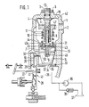
- FIG. 1 shows part of a fuel injection pump, which can be, for example, a distributor fuel injection pump.
- a control lever 41 in a known manner, which is adjustable by a speed controller (not shown) against the force of a control spring 22 and actuates a quantity adjustment element of the fuel injection pump.
- the control lever can also be referred to as a fuel quantity adjusting element.
- the control lever abuts an adjustable stop 29 at full load, which in the example shown is at the end of a rocker 20, the other end of which rests on a scanning pin 19. This is guided in a bore 30 and projects vertically into a cylinder 31 arranged in the distributor injection pump housing 1 of the fuel injection pump.
- An actuating piston 13 is guided in this and delimits a working space 33 on its one end set 32 in the cylinder 31. This is constantly connected via an opening 35 located on the end face 34 of the cylinder 31 to a space which is filled with pressure medium, the pressure of which rotates is controlled depending on the number.
- this space is the fuel-filled suction space 36 of the fuel injection pump, the fuel being supplied by a fuel pump 39, which draws fuel from a fuel reservoir 37 and whose delivery side can be relieved via a pressure control valve 38.
- This arrangement results in a speed-dependent pressure in the suction chamber 36 in a known manner.
- the actuating piston 13 In the area of penetration of the stylus 19 into the cylinder 31, the actuating piston 13 has a sensing body 14, the outer surface of which describes a space curve by which the position of the stylus 19 is determined when the actuating piston 13 is displaced.
- the actuating piston 13 in connection with the scanning body 14 and the scanning device comprising the scanning pin 19 and the rocker 20 represents an adjusting device 28 of the full-load stop 29, which limits the free path of the quantity adjusting member 40 in one direction.
- the cylinder 31 opens into a leakage space 42, which is closed by the distributor injection pump housing 1:
- An adjusting mandrel 3 which extends through the wall of the injection pump housing 1 and extends from the part protruding from the distributor injection pump housing 1, projects coaxially into the leakage space 42. is provided with an external thread and has an internal hexagon 12 or another form-fitting surface on its end face, via which the setting mandrel 3 can be rotated.
- the setting mandrel 3 is pressed with a collar 16 against the inner wall of the distributor injection pump housing and thus secured axially and in the rotational position.
- the setting mandrel is rotationally connected to the actuating piston 13.
- the rotational position of the setting mandrel 3 can be adjusted by means of a tool which engages in the hexagon socket.
- the scanning effective rotational position of the scanning body 14 becomes the maximum possible with the longitudinal position Strokes of the sensing body 14 determines, wherein the setting mandrel 3 is at least indirectly supported on the distributor injection pump housing 1 of the fuel injection pump.
- an internal thread is introduced into which a pin 7 with a guide surface 9 for the actuating piston 13 is screwed.
- the setting mandrel 3 is thus made in two parts. This pin 7 can be fixed in a specific position via a further pin lock nut 8.
- This pin screwed into the setting mandrel 3 projects coaxially to the axis of the cylinder 31 into it and into an axial blind bore 46 extending from the rear end face 43 of the actuating piston 13 even when the actuating piston 13, as shown in FIG Starting position is located on the end face 34 of the cylinder 31.
- the end of the pin 7 screwed into the setting mandrel protrudes into the blind bore 46 and has a guide surface 9 which is adapted to an opening 45a in a drive plate 45 inserted into the actuating piston on the rear end face 43.
- the driving plate is non-rotatably connected to the actuating piston 13.
- the setting mandrel 3 has a pin collar 44.
- This serves as a stop for the driving plate 45 and thus limits the longitudinal displacement of the actuating piston 13 against the force of a return spring 10 arranged between the driving plate 45 and the spring plate 5.
- the end face 50 of the pin 7 which dips into the blind bore 46 can also serve as a stop.
- the preload of the return spring 10 is set by loosening the nut 6 by turning the setting mandrel 3.
- This setting can also be carried out while the internal combustion engine or distributor fuel injection pump is running, for which purpose an automatic setting device can also be used.
- This twisting means that a spring element, a holding part 4, Secured spring plate 5, which is arranged on an external thread located on the inner part of the setting mandrel 3 adjoining the collar 16, is adjusted in the axial direction.
- the setting mandrel is fixed on the outside of the distributor injection pump housing again in a certain position by the nut 6.
- a greater or lesser speed-dependent pressure must be applied in the suction chamber 36 in order to adjust the control piston 13 with the scanning body 14 in the axial direction.
- the spring plate is provided on a cylindrical part directed towards the scanning body with a round thread onto which individual turns of the return spring 10 are screwed.
- the end 11 of the screwed-on spring 10 comes to rest as a support or return spring twist fixation on a radial surface of the distributor injection pump housing 1 which runs in the direction of the setting mandrel axis and on which it can move longitudinally.
- the spring stiffness is adjusted through an actuating opening 2 in the distributor injection pump housing 1 through which an actuator or tool can be guided, which engages in locking points arranged on the circumference of the spring plate and thus the spring plate while overcoming the forces of the holding part 4, which is designed as a resilient arm with its engages free end in these locking points 47 and thus secures the spring plate from twisting, twisted.
- the spring characteristic or spring stiffness is changed by this twisting or screwing of more or fewer threads onto the round thread of the spring plate.
- This adjustment can also be carried out by an automatic setting machine when the distributor injection pump is operated. After the setting, the opening 2 is sealed by a stopper.
- the stroke in the embodiment according to FIG. 1 is made on the removed setting mandrel.
- the thread Pin nut 8 loosened and the pin 7 screwed into the setting mandrel according to the intended stroke and the set screw nut 8 countered again.
- the device works so that with increasing speed and thus increasing suction chamber pressure in the suction chamber 36, the actuating piston 13 with the scanning body 14 is displaced against the return spring 10.
- the tracer pin follows a generatrix of the tracer body 14 and adjusts the position of the full-load stop 29. In this way, a specific full-load characteristic curve of the fuel injection pump is obtained in full-load operation as a function of the speed.
- the correction of the full-load injection quantity depends on the course of the curve on the sensing body 14 and on the characteristic and preload of the return spring 10 or on the pressure course of the fuel pressure in the suction space 36 over all speed ranges.
- the prescribed configuration provides the possibility of changing both the characteristic and the pretensioning of the return spring 10 and also of using a certain scanning curve. Furthermore, the effective stroke of the adjusting piston 13 can also be adjusted, so that it can be achieved that from a certain speed no change in the full-load stop adjustment takes place.
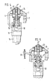
- FIG. 2 shows an embodiment which is further developed than in FIG. 1, in which the pin 7 of FIG. 1 forming an inner part of the setting mandrel 3 ⁇ is designed as a through pin 7 ⁇ which is screwed through the setting mandrel 3 ⁇ and protrudes from it at both ends.
- the setting mandrel 3 ⁇ and the pin 7 ⁇ are fixed. This fixation of both devices is achieved in that the setting mandrel 3 ⁇ is slotted in the area of its external thread at the end protruding from the inside of the injection pump, which end can be jammed as a result.
- the passage pin 7 ⁇ is cylindrical in this area.
- the mandrel parts formed by slots 48 are pressed onto the through pin 7 ⁇ and at the same time the mandrel 3 ⁇ is clamped to the wall of the injection pump housing via the collar 16, which is also provided here.
- the pin 7 ⁇ can be adjusted in the longitudinal direction by a thread attached to the inside of the setting mandrel, which interacts with the external thread of the pin 7.
- the stroke of the actuating piston 13 with the sensing body 14 can be adjusted externally, in the fully assembled state of the fuel injection pump, in particular also by means of an automatic adjusting device, as is the case with the adjustment of the preload and characteristic of the spring in FIG. 1 is.
- the through pin 7 ⁇ is held in its rotational position and the spring preload is set by rotating the setting mandrel, as described above. Then both adjusting members can be fixed by the nut 6.
- both adjusting members can be fixed by the nut 6.
- the spring stiffness and the preload can be set as described in FIG. 1.
- the slots 48 serve as positive locking surfaces for a twisting tool.
- Figure 3 discloses an alternative in which only one adjustment of the bias of the return spring is provided.
- the stroke of the actuating piston 13 and its rotational position can be changed.
- the spring stiffness can also be used when using a progressive back adjusting spring by adjusting the rotation of the spring plate using a tool.
- the spring preload change is not caused here by turning the one-piece here with a continuous external thread adjusting mandrel 3 ⁇ , which is screwed through the injection pump housing wall.
- the spring plate 5 is also blocked in the direction of rotation by the holding part 4
- only the stroke and the rotational position of the actuating piston 13 are set by screwing the setting mandrel.
- the pitch of the thread of the setting mandrel 3 ⁇ is selected so that the tolerance height during the stroke corresponds to one thread revolution of the setting mandrel and therefore the scanning body 14 remains adjustable.
- the pretension is adjusted by rotating the spring plate 5 by means of a tool inserted through the actuating opening 2, which in turn acts on the locking points of the spring plate.
- FIG. 4 A modified embodiment of the device according to FIG. 1 is disclosed in FIG. 4, in which the stroke of the actuating piston 13 is not adjusted by the pin 7 provided there, but by an adjusting bush 23 that can be screwed into the wall of the distributor injection pump and secured by a lock nut 24 against the injection pump wall is adjustable, which in turn carries a now one-piece setting mandrel 3 ⁇ .
- This is guided in a through bore 49 of the adjusting bush 23 in the area of which it is cylindrical and provided with a seal and, like the adjusting mandrel 7 in FIG. 1, has a collar 16, via which it is screwed onto the external thread by means of the nut 6 the adjusting bush is clamped and can be fixed in this way.
- the nut 6 is loosened on the setting mandrel 3 ⁇ and the adjusting bush 23 is screwed more or less into the distributor injection pump housing 1 by turning it.
- the setting mandrel 3 ⁇ fixed over the collar 16 is also displaced and the end face 50 of the setting mandrel 3 ⁇ serving as a stop is displaced toward the actuating piston 13.
- the space curve of the scanning body to the scanning pin can be adjusted by rotating the setting mandrel 3 Vietnamese according to the above description and the spring can then be adjusted in the same way by rotating the spring plate on the adjusting mandrel by means of an actuator or tool inserted through the actuating opening 2.
- Figure 5 discloses an embodiment corresponding to version 4, in which, however, a spring plate 5 ⁇ is provided with an externally screwable return spring, but with a smooth inner bore 51. This is shifted by a lever through the injection pump wall to the outside on the setting mandrel 3 ⁇ , which is also smoothly cylindrical in this area.
- the lever position can be secured by an adjustable stop or the lever can be adjusted by means of a spindle guide 26.
- the rotational position of the spring plate 5 ⁇ which determines the spring characteristic is retained thanks to the fixing provided here, as in FIG. 4, by the holding part 4 described in FIG.
- the device shown in Figure 5 works so that the spring preload, the spring stiffness, the stroke of the actuating piston and the position of the sensing body relative to the stylus can be adjusted independently of each other and from the outside, for which purpose an automatic adjusting device can also be used.
Landscapes
- Engineering & Computer Science (AREA)
- Chemical & Material Sciences (AREA)
- Combustion & Propulsion (AREA)
- Mechanical Engineering (AREA)
- General Engineering & Computer Science (AREA)
- Fuel-Injection Apparatus (AREA)
- High-Pressure Fuel Injection Pump Control (AREA)
Applications Claiming Priority (2)
| Application Number | Priority Date | Filing Date | Title |
|---|---|---|---|
| DE19873709366 DE3709366A1 (de) | 1987-03-21 | 1987-03-21 | Kraftstoffeinspritzpumpe fuer brennkraftmaschinen |
| DE3709366 | 1987-03-21 |
Publications (3)
| Publication Number | Publication Date |
|---|---|
| EP0283709A2 true EP0283709A2 (fr) | 1988-09-28 |
| EP0283709A3 EP0283709A3 (en) | 1990-01-31 |
| EP0283709B1 EP0283709B1 (fr) | 1991-07-24 |
Family
ID=6323705
Family Applications (1)
| Application Number | Title | Priority Date | Filing Date |
|---|---|---|---|
| EP19880102271 Expired - Lifetime EP0283709B1 (fr) | 1987-03-21 | 1988-02-17 | Pompe d'injection de combustible pour moteurs à combustion interne |
Country Status (3)
| Country | Link |
|---|---|
| EP (1) | EP0283709B1 (fr) |
| JP (1) | JP2648331B2 (fr) |
| DE (2) | DE3709366A1 (fr) |
Family Cites Families (5)
| Publication number | Priority date | Publication date | Assignee | Title |
|---|---|---|---|---|
| DE2908792A1 (de) * | 1979-03-07 | 1980-09-11 | Bosch Gmbh Robert | Steuereinrichtung fuer brennkraftmaschinen, insbesondere ladedruckabhaengiger vollastanschlag fuer aufgeladene fahrzeug-dieselmotoren |
| JPS594970B2 (ja) * | 1981-04-02 | 1984-02-02 | 双葉電機工業株式会社 | 原料肉用自動注射機 |
| DE3146499A1 (de) * | 1981-11-24 | 1983-06-01 | Robert Bosch Gmbh, 7000 Stuttgart | Kraftstoffeinspritzpumpe fuer brennkraftmaschinen |
| DE3245947A1 (de) * | 1982-12-11 | 1984-06-14 | Robert Bosch Gmbh, 7000 Stuttgart | Kraftstoffeinspritzpumpe fuer brennkraftmaschinen |
| DE3327370A1 (de) * | 1983-07-29 | 1985-02-14 | Robert Bosch Gmbh, 7000 Stuttgart | Kraftstoffeinspritzpumpe fuer aufgeladene diesel-brennkraftmaschinen, insbesondere verteilereinspritzpumpe |
-
1987
- 1987-03-21 DE DE19873709366 patent/DE3709366A1/de not_active Withdrawn
-
1988
- 1988-02-17 DE DE8888102271T patent/DE3863804D1/de not_active Expired - Lifetime
- 1988-02-17 EP EP19880102271 patent/EP0283709B1/fr not_active Expired - Lifetime
- 1988-03-22 JP JP63065958A patent/JP2648331B2/ja not_active Expired - Lifetime
Also Published As
| Publication number | Publication date |
|---|---|
| DE3863804D1 (de) | 1991-08-29 |
| JPS63253128A (ja) | 1988-10-20 |
| DE3709366A1 (de) | 1988-09-29 |
| EP0283709A3 (en) | 1990-01-31 |
| JP2648331B2 (ja) | 1997-08-27 |
| EP0283709B1 (fr) | 1991-07-24 |
Similar Documents
| Publication | Publication Date | Title |
|---|---|---|
| DE3590194C2 (de) | Brennstoff-Einspritzpumpe | |
| EP0116168A2 (fr) | Pompe d'injection de combustible | |
| DE3144500C2 (de) | Mit einem hydraulischen Spritzversteller versehene Verteilereinspritzpumpe | |
| DE1258187B (de) | Kraftstoffeinspritzpumpe fuer Brennkraftmaschinen | |
| DE3617732C2 (fr) | ||
| DE2349692A1 (de) | Drehzahlregler einer kraftstoffeinspritzpumpe | |
| DE3207807C2 (de) | Kraftstoff-Einspritzpumpe für einen Verbrennungsmotor | |
| DE3424883A1 (de) | Kraftstoffeinspritzpumpe fuer brennkraftmaschinen | |
| DE3435987A1 (de) | Kraftstoffeinspritzpumpe fuer brennkraftmaschinen | |
| DE3535005C2 (fr) | ||
| DE3405540C2 (fr) | ||
| EP0273225A2 (fr) | Pompe d'injection de combustible pour moteurs à combustion interne | |
| EP0283709B1 (fr) | Pompe d'injection de combustible pour moteurs à combustion interne | |
| DE4129837C2 (de) | Drehzahlregler für Kraftstoffeinspritzpumpen von Brennkraftmaschinen | |
| DE2342107A1 (de) | Drehzahlregler fuer kraftstoffeinspritzpumpen | |
| DE3630871C2 (fr) | ||
| DE3323761C2 (fr) | ||
| EP0262167B1 (fr) | Pompe d'injection de carburant pour moteurs a combustion interne | |
| EP0424797B1 (fr) | Soupape de commande pour l'injection de combustible | |
| DE3141850C2 (de) | Druckventil für eine Kraftstoff-Einspritzpumpe einer Brennkraftmaschine | |
| EP0209681B1 (fr) | Régulateur de vitesse de rotation pour pompes à injection de combustible | |
| DE3421560A1 (de) | Vorrichtung zur einstellung der federcharakteristik einer schraubenfeder | |
| DE3245947C2 (fr) | ||
| EP0627552A1 (fr) | pompe à injection de carburant | |
| EP0624720B1 (fr) | Pompe d'injection de combustible pour moteurs à combustion interne |
Legal Events
| Date | Code | Title | Description |
|---|---|---|---|
| PUAI | Public reference made under article 153(3) epc to a published international application that has entered the european phase |
Free format text: ORIGINAL CODE: 0009012 |
|
| AK | Designated contracting states |
Kind code of ref document: A2 Designated state(s): DE FR GB |
|
| PUAL | Search report despatched |
Free format text: ORIGINAL CODE: 0009013 |
|
| AK | Designated contracting states |
Kind code of ref document: A3 Designated state(s): DE FR GB |
|
| RHK1 | Main classification (correction) |
Ipc: F02D 1/10 |
|
| 17P | Request for examination filed |
Effective date: 19900621 |
|
| 17Q | First examination report despatched |
Effective date: 19910108 |
|
| GRAA | (expected) grant |
Free format text: ORIGINAL CODE: 0009210 |
|
| AK | Designated contracting states |
Kind code of ref document: B1 Designated state(s): DE FR GB |
|
| ET | Fr: translation filed | ||
| REF | Corresponds to: |
Ref document number: 3863804 Country of ref document: DE Date of ref document: 19910829 |
|
| GBT | Gb: translation of ep patent filed (gb section 77(6)(a)/1977) | ||
| RAP4 | Party data changed (patent owner data changed or rights of a patent transferred) |
Owner name: ROBERT BOSCH GMBH |
|
| PLBE | No opposition filed within time limit |
Free format text: ORIGINAL CODE: 0009261 |
|
| STAA | Information on the status of an ep patent application or granted ep patent |
Free format text: STATUS: NO OPPOSITION FILED WITHIN TIME LIMIT |
|
| 26N | No opposition filed | ||
| PGFP | Annual fee paid to national office [announced via postgrant information from national office to epo] |
Ref country code: DE Payment date: 19991230 Year of fee payment: 13 |
|
| PGFP | Annual fee paid to national office [announced via postgrant information from national office to epo] |
Ref country code: GB Payment date: 20000214 Year of fee payment: 13 |
|
| PGFP | Annual fee paid to national office [announced via postgrant information from national office to epo] |
Ref country code: FR Payment date: 20000222 Year of fee payment: 13 |
|
| PG25 | Lapsed in a contracting state [announced via postgrant information from national office to epo] |
Ref country code: GB Free format text: LAPSE BECAUSE OF NON-PAYMENT OF DUE FEES Effective date: 20010217 |
|
| GBPC | Gb: european patent ceased through non-payment of renewal fee |
Effective date: 20010217 |
|
| PG25 | Lapsed in a contracting state [announced via postgrant information from national office to epo] |
Ref country code: FR Free format text: LAPSE BECAUSE OF NON-PAYMENT OF DUE FEES Effective date: 20011031 |
|
| REG | Reference to a national code |
Ref country code: FR Ref legal event code: ST |
|
| PG25 | Lapsed in a contracting state [announced via postgrant information from national office to epo] |
Ref country code: DE Free format text: LAPSE BECAUSE OF NON-PAYMENT OF DUE FEES Effective date: 20011201 |