EP0283786A1 - Localisateur digital - Google Patents
Localisateur digital Download PDFInfo
- Publication number
- EP0283786A1 EP0283786A1 EP88103281A EP88103281A EP0283786A1 EP 0283786 A1 EP0283786 A1 EP 0283786A1 EP 88103281 A EP88103281 A EP 88103281A EP 88103281 A EP88103281 A EP 88103281A EP 0283786 A1 EP0283786 A1 EP 0283786A1
- Authority
- EP
- European Patent Office
- Prior art keywords
- equation
- frequency
- value
- operation means
- current
- Prior art date
- Legal status (The legal status is an assumption and is not a legal conclusion. Google has not performed a legal analysis and makes no representation as to the accuracy of the status listed.)
- Granted
Links
Images



Classifications
-
- G—PHYSICS
- G01—MEASURING; TESTING
- G01R—MEASURING ELECTRIC VARIABLES; MEASURING MAGNETIC VARIABLES
- G01R31/00—Arrangements for testing electric properties; Arrangements for locating electric faults; Arrangements for electrical testing characterised by what is being tested not provided for elsewhere
- G01R31/08—Locating faults in cables, transmission lines, or networks
- G01R31/088—Aspects of digital computing
Definitions
- the present invention relates to a digital locator which is applicable to location fault point of power system.
- Fig. 1 is the simplified block diagram of a power-system to which the digital locator related to the invention is applicable.
- the power system connected with the digital type locator is comprised of the following; generator 1, bus 2, transmission line 3, fault point 4, current transformer 5, potential transformer 6, digital locator 10, a current transformer 11 which converts the output of the current transformer 5 into an adequate value, a voltage transformer 12 which converts the output of the potential transformer 6 into an adequate value, filtering circuits 21 and 22 which respectively eliminate restricted frequency bands from sampled theorem, a circuit 31 which samples AC input current at constant intervals before sequentially A-D converting it into digital values, and operation circuit 100.
- the reference numeral 4 denotes the fault point in the power system.
- bus voltage v can be calculated by applying an equation shown below.
- v Ri + L di dt (1-1)
- R represents the resistance value of transmission line up to the position where the fault point is present
- L the inductance value
- i the fault current
- This preceding invention provides means for approximating the integrated value of current by applying the integration shown below, in which current values are denoted to be i(n), i(n+1), and i(n+2) after continuously sampling those current values at constant sampling intervals between times t n , t n+1 and t n+2 , respectively,
- current values are denoted to be i(n), i(n+1), and i(n+2) after continuously sampling those current values at constant sampling intervals between times t n , t n+1 and t n+2 , respectively.
- a first object of this invention is to thoroughly solve those problems mentioned above by providing a novel digital type locator which is capable of securely improving frequency characteristic throughout entire higher frequency bands.
- the digital locator related to the invention determines the resistance value R and the inductance valve L by working out a simultaneous equation derived from those preceding equations (1-2) and (1-3) produced by integration of the equation (1-1) which denotes the condition of the transmission line from the time t n-1 to t n+1 and from t n to t n+2 , respectively.
- the apparatus related to the invention applies a constant sampling amount corresponding to an odd number and then executes integration by multiplying error present in higher frequency by corrective coefficient before eventually determining the approximation, thus securely improving frequency characteristic in higher frequency.
- the present invention substantially includes the first invention using odd number of sampled amount and the second invention using even number of sampled amount, respectively.
- the operation circuit 100 shown in Fig. 1 is made of a microprocessor for example, which can eliminate errors from higher harmonic by computing the equation (1-4) shown below so that the object of the invention can be fulfilled.
- numerators A through F respectively denote the following relationships
- ⁇ EB-FD
- Fig. 2 is the simplified block diagram denoting the constitution of a preferred embodiment of the apparatus related to the invention for explaining the functional operations of the operation circuit 100, which is comprised of the following circuits; circuits 111 through 114 which respectively extract the substance of approximate integrations, in which the circuit 111 extracts the expression A, circuit 112 the expression C, circuit 113 the expression E, and circuit 114 extracts the expression F.
- Subtraction circuits 115 and 116 respectively calculate expressions B and D.
- the operation circuit 121 calculates AB-CD
- operation circuit 122 calculates CE-AF
- the operation circuit 123 calculates ⁇ .
- Division circuits 131 and 132 respectively extract resistance components R and inductance components L up to the fault point.
- the digital locator can be materialized by producing the integrated value of current and voltage
- the method of determining the integrated value of current and voltage by applying digital amount is described below.
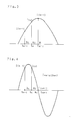
- the ⁇ denotes the phase angle against the voltage vector (not shown).
- i(n-2), i(n), and i(n+1) are respectively the values extracted by sampling operation done by applying momentary values of current i at times t n-1 , t n and t n+1 .
- more amount of errors can be reduced than the method considered before by adding the area of a square surrounded by b1 - i(n-1) - i(n) - a0 to the area of another square surrounded by a0 - i(n) - i(n+1)- a1 by applying a mediate sampled value.
- the first invention provides a method of minimizing error components up to higher harmonic bands by applying more number of sampled values corresponding to odd number rather than merely adjusting the sampling intervals. This novel method is described below.
- the corrected approximate integration should be expressed by the equation shown below by multiplying the equation (1-6) by C.
- the first invention provides a polynomial expression using approximate integrating expressions by applying odd number of sampled values without varying sampling intervals on condition that the applicable odd number should fully satisfy (the odd-number ⁇ ⁇ 2 ⁇ ), while multiplying each term by corrective coefficient by applying a specific frequency so that the amount of error can eventually be reduced to zero.
- the integrated value of the true value I is expressed by the equation shown below. Accordingly, corrective coefficients for equalizing the integrated approximate value S T and the true value I can be determined by converting equations (1-15) and (1-16) into an identical equation, which is expressed in the following equation (1-17) after deleting similar terms.
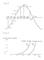
- Fig. 6 denotes the frequency characteristic curve 200 which represents approximate error percentage against the true value in the vertical axis and the rate of degree f/f0 between harmonics waves f and the fundamental wave frequency f0 in the horizontal axis after substituting the corrective coefficients K1 and K2 into the approximate integration of the equation (1-14) following the calculation of these corrective coefficients by executing a 3-point sampling operation at 30° of sampling intervals ⁇ .
- the method of executing the 3-point sampling operation is conventionally known by a proposal made by a prior art.
- the present invention allows the number of sampling operation to be increased by applying odd-number sampling points like 5 or 7 points for example so that errors can perfectly be eliminated from extensive frequencies including higher harmonic bands.
- the corrective coefficients K1 through K4 can be calculated by working out simultaneous equations derived from the following four expressions.
- Fig. 6 also denotes the frequency characteristic curve 300 generated from the execution of the approximate integration of the preceding equation (1-14) following the calculation of the corrective coefficients by executing a 7-point sampling operation at 30° of sampling intervals ⁇ .
- the preferred embodiment of the apparatus related to the first invention thoroughly eliminates even the slightest amount of errors from extensive frequencies including higher harmonic bands by calculating corrective coefficients in the approximate integrated equation (1-14) based on the method described above, thus eventually improving the entire frequency characteristic.
- the foregoing description of the first invention has solely referred to method of approximately calculating the integrated values by applying the odd-number of sampled values. It should be understood however that the apparatus related to the invention also approximately calculates the integrated values by applying the even-number of sampled values by means of the second invention described below.
- the operation circuit 100 shown in Fig. 1 is substantially comprised of a microcomputer for example. By allowing the operation circuit 100 to process the equation (2-1) shown below, errors present in high-harmonic can perfectly be eliminated in order that the object of the invention can be fulfilled.
- the ⁇ denotes the phase angle against the voltage vector (not shown).
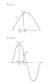
- i(n-1) and i(n) respectively denote the values sampled by respective momentary values of current i at times t n-1 and t n .
- the integrated value of current i from, time t n-1 to t n can approximately and easily be calculated by applying the method described below.
- the integrated value of current i can approximately be calculated by applying the area of a square surrounded by b1 - i(n-1) - i(n) - a1.
- the calculated integrated values should approximate to each other. Nevertheless, as shown in Fig. 8, when a specific frequency that doubles the frequency component shown in Fig. 7 is applied, more amount of error component grows in the area of the above-cited square surrounded by b1 - n(n-1) - i(n) - a1 than the true value.
- the second invention hereby proposes a method of minimizing the amount of error component up to higher harmonic wave bands by effectively applying a number of the even-number sampled values rather than depending on the sampling interval.
- integrated approximate value of current i from time t n-1 to t n can be calculated by applying area S of the square surrounded by b1 - i(n-1) - i(n) - a1.
- the following equation denotes the multiplication of the approximate value by the corrective coefficient K1 used for correcting error against the true value.
- S K ⁇ 2 ⁇ i(n-1)+i(n) ⁇
- the value of the corrective coefficient K1 is determined in the above equation to allow no error to be present in a specific frequency like the basic wave component, for example, error components cannot perfectly be eliminated from other frequencies like the one that doubles the basic wave frequency.
- the following equation is established by first multiplying the square area surrounded by b2 - i(n-2) - i(n+1) - a2 by the corrective coefficient K2, followed by addition of the product of this multiplication to S shown in the above equation.
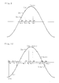
- equation (2-2) being the approximate integration is established by increasing the number of the sampled value as shown in Fig. 10.
- values of the corrective coefficients K1 through K3 can respectively be determined by working out the following determinants.
- Fig. 11 denotes the frequency characteristic curve 400 which represents approximate error percentage against the true value in the vertical axis and the relationship f/f0 between harmonic wave f and the the fundamental wave frequency f0 in the horizontal axis after substituting the corrective coefficients K1 through K3 into the approximate integration of the preceding equation (2-2) following the calculation of those corrective coefficients by executing a 6-point sampling operation at 30° of sampling interval ⁇ .
- values of the corrective coefficients K through K4 can respectively be determined by working out those determinants shown below.
- Fig. 11 also denotes the frequency characteristic curve 500 which represents approximate error percentage in the vertical axis occurring when the 8-point sampling operation is executed.
- the preferred embodiment of the apparatus related to the invention securely calculates both the resistance component value R and the inductance component value L up to the faulty point present in the power system by working out the simultaneous equation derived from those equations (2-6) and (2-7) shown above, followed by substitution of the approximately integrated values calculated by the equation (1-1) into the integration terms shown below.
- any conventional three-phase power system applies line-to-line voltage and line-to-line current to the short-circuit digital locator and also applies phase current compensating for the phase-voltage and zero-phase voltage to the ground digital locator, respectively.
- the locator related to the invention may first store the data of voltage and in current memory when the power system is out of order, and then, it calculates those values R and L by referring to those stored data later on.
- the apparatus related to the invention can effectively be applied to any distance relay device by employing a number of sampled values within allowable range of operation time.
- the locator related to the invention can also be used for generating scalar quantity of voltage and current.
- the digital locator related to the invention provides corrective coefficients for dealing with error components present in high-frequency waves, the apparatus securely and significantly improves frequency characteristic of extensive frequencies including extremely high frequency bands.
Landscapes
- Physics & Mathematics (AREA)
- Engineering & Computer Science (AREA)
- Mathematical Physics (AREA)
- Theoretical Computer Science (AREA)
- General Physics & Mathematics (AREA)
- Emergency Protection Circuit Devices (AREA)
Applications Claiming Priority (4)
| Application Number | Priority Date | Filing Date | Title |
|---|---|---|---|
| JP4942287A JPH0833425B2 (ja) | 1987-03-03 | 1987-03-03 | デジタル型故障点標定装置 |
| JP49422/87 | 1987-03-03 | ||
| JP62049421A JPH0616067B2 (ja) | 1987-03-03 | 1987-03-03 | デジタル型故障点標定装置 |
| JP49421/87 | 1987-03-03 |
Publications (2)
| Publication Number | Publication Date |
|---|---|
| EP0283786A1 true EP0283786A1 (fr) | 1988-09-28 |
| EP0283786B1 EP0283786B1 (fr) | 1992-09-02 |
Family
ID=26389812
Family Applications (1)
| Application Number | Title | Priority Date | Filing Date |
|---|---|---|---|
| EP88103281A Expired EP0283786B1 (fr) | 1987-03-03 | 1988-03-03 | Localisateur digital |
Country Status (4)
| Country | Link |
|---|---|
| US (1) | US4985843A (fr) |
| EP (1) | EP0283786B1 (fr) |
| AU (1) | AU603871B2 (fr) |
| DE (1) | DE3874174T2 (fr) |
Families Citing this family (6)
| Publication number | Priority date | Publication date | Assignee | Title |
|---|---|---|---|---|
| EP0459522B1 (fr) * | 1990-05-31 | 1995-12-20 | Nissin Electric Company, Limited | Méthode de localisation de défaut pour une ligne de transmission à deux branches parallèles avec N sorties |
| FR2690573B1 (fr) * | 1992-04-28 | 1997-05-09 | Merlin Gerin | Dispositif de controle de defaut homopolaire dans un reseau de distribution electrique. |
| SE9201972L (sv) * | 1992-06-26 | 1993-11-29 | Asea Brown Boveri | Förfarande och anordning för att bestämma den felström som uppstår vid ett fel på kraftlinjer vid kortslutning mellan fas/faser till jord |
| US5428549A (en) * | 1993-05-28 | 1995-06-27 | Abb Power T&D Company | Transmission line fault location system |
| US6397156B1 (en) * | 1998-11-17 | 2002-05-28 | Abb Inc. | Impedance measurement system for power system transmission lines |
| US6559630B2 (en) * | 2001-07-06 | 2003-05-06 | Phoenixtec Power Co., Ltd. | Method of measuring frequency of AC power |
Citations (3)
| Publication number | Priority date | Publication date | Assignee | Title |
|---|---|---|---|---|
| US3983377A (en) * | 1974-07-08 | 1976-09-28 | Bbc Brown Boveri & Company Limited | Method and apparatus for detecting a fault location at an electrical conductor |
| FR2485741A1 (fr) * | 1980-06-30 | 1981-12-31 | Mitsubishi Electric Corp | Appareil de detection de la valeur de crete d'une intensite et de la valeur de crete d'une tension |
| EP0214483A1 (fr) * | 1985-08-13 | 1987-03-18 | Mitsubishi Denki Kabushiki Kaisha | Méthode pour mesurer la distance dans des relais digitaux à distance |
Family Cites Families (6)
| Publication number | Priority date | Publication date | Assignee | Title |
|---|---|---|---|---|
| DE1538421B2 (de) * | 1966-03-02 | 1977-10-20 | Denzel, Paul, Prof. Dr.-Ing, 5100 Aachen | Schnelldistanzschutz nach dem prinzip des nulldurchgangsvergleiches mit einem auch bei transienten vorgaengen unveraenderlichen ausloesepolygon |
| JPS52100149A (en) * | 1976-02-18 | 1977-08-22 | Tokyo Electric Power Co Inc:The | Digital failure point evaluating unit |
| JPS55127829A (en) * | 1979-03-27 | 1980-10-03 | Tokyo Shibaura Electric Co | Digital distance relay unit |
| JPS6039312A (ja) * | 1983-08-10 | 1985-03-01 | 株式会社東芝 | 保護継電装置 |
| JPH0828934B2 (ja) * | 1984-07-31 | 1996-03-21 | 株式会社東芝 | 保護制御装置 |
| SE452533B (sv) * | 1986-04-08 | 1987-11-30 | Asea Ab | Forfarande for riktningsdetektering av fel pa en kraftledning samt anordning for genomforande av det nemnda forfarandet |
-
1988
- 1988-03-02 AU AU12552/88A patent/AU603871B2/en not_active Ceased
- 1988-03-03 DE DE8888103281T patent/DE3874174T2/de not_active Expired - Lifetime
- 1988-03-03 EP EP88103281A patent/EP0283786B1/fr not_active Expired
-
1989
- 1989-12-26 US US07/453,197 patent/US4985843A/en not_active Expired - Lifetime
Patent Citations (3)
| Publication number | Priority date | Publication date | Assignee | Title |
|---|---|---|---|---|
| US3983377A (en) * | 1974-07-08 | 1976-09-28 | Bbc Brown Boveri & Company Limited | Method and apparatus for detecting a fault location at an electrical conductor |
| FR2485741A1 (fr) * | 1980-06-30 | 1981-12-31 | Mitsubishi Electric Corp | Appareil de detection de la valeur de crete d'une intensite et de la valeur de crete d'une tension |
| EP0214483A1 (fr) * | 1985-08-13 | 1987-03-18 | Mitsubishi Denki Kabushiki Kaisha | Méthode pour mesurer la distance dans des relais digitaux à distance |
Also Published As
| Publication number | Publication date |
|---|---|
| DE3874174T2 (de) | 1992-12-17 |
| DE3874174D1 (de) | 1992-10-08 |
| US4985843A (en) | 1991-01-15 |
| AU1255288A (en) | 1988-09-01 |
| EP0283786B1 (fr) | 1992-09-02 |
| AU603871B2 (en) | 1990-11-29 |
Similar Documents
| Publication | Publication Date | Title |
|---|---|---|
| George et al. | Harmonic power flow determination using the fast Fourier transform | |
| JP3786372B2 (ja) | ディジタル電流差分システム | |
| Guo et al. | Simplified algorithms for removal of the effect of exponentially decaying DC-offset on the Fourier algorithm | |
| Hart et al. | A new frequency tracking and phasor estimation algorithm for generator protection | |
| Grady et al. | Minimizing network harmonic voltage distortion with an active power line conditioner | |
| EP0244649B1 (fr) | Procédé et dispositif de protection d'une ligne pour transmission de puissance | |
| Łobos | Nonrecursive methods for real-time determination of basic waveforms of voltages and currents | |
| EP0322518B1 (fr) | Relais protecteur numérique | |
| US5045777A (en) | Electric signal producing system | |
| Zečević et al. | Dynamic harmonic phasor estimation by adaptive Taylor-based bandpass filter | |
| US5081413A (en) | Method and apparatus for measuring AC power | |
| EP0283786A1 (fr) | Localisateur digital | |
| US6147475A (en) | Prediction of harmonic distortion and application of power-factor correction in AC power systems | |
| US4795974A (en) | Digital energy meter | |
| US4051357A (en) | Double odd discrete fourier transformer | |
| JPH0320969B2 (fr) | ||
| Cole | A nearly exact second‐order finite‐difference time‐domain wave propagation algorithm on a coarse grid | |
| Várkonyi-Kóczy et al. | A fast filter-bank for adaptive Fourier analysis | |
| EP0214483B1 (fr) | Méthode pour mesurer la distance dans des relais digitaux à distance | |
| US5475559A (en) | Negative-sequence time-overcurrent relay | |
| Nastov et al. | Time-mapped harmonic balance | |
| Blanchard et al. | FPGA Implementation of IEC 61000-4-30 Quasi-Peak meter with CORDIC Algorithm | |
| Lawrence et al. | Recursive identification for system models of transfer function type | |
| Bertocco et al. | Numerical algorithms for power measurements | |
| Principe et al. | Microcomputer-based digital filters for EEG processing |
Legal Events
| Date | Code | Title | Description |
|---|---|---|---|
| PUAI | Public reference made under article 153(3) epc to a published international application that has entered the european phase |
Free format text: ORIGINAL CODE: 0009012 |
|
| AK | Designated contracting states |
Kind code of ref document: A1 Designated state(s): CH DE FR GB LI SE |
|
| 17P | Request for examination filed |
Effective date: 19881118 |
|
| 17Q | First examination report despatched |
Effective date: 19911119 |
|
| GRAA | (expected) grant |
Free format text: ORIGINAL CODE: 0009210 |
|
| AK | Designated contracting states |
Kind code of ref document: B1 Designated state(s): CH DE FR GB LI SE |
|
| REF | Corresponds to: |
Ref document number: 3874174 Country of ref document: DE Date of ref document: 19921008 |
|
| ET | Fr: translation filed | ||
| PLBE | No opposition filed within time limit |
Free format text: ORIGINAL CODE: 0009261 |
|
| STAA | Information on the status of an ep patent application or granted ep patent |
Free format text: STATUS: NO OPPOSITION FILED WITHIN TIME LIMIT |
|
| 26N | No opposition filed | ||
| EAL | Se: european patent in force in sweden |
Ref document number: 88103281.7 |
|
| REG | Reference to a national code |
Ref country code: GB Ref legal event code: IF02 |
|
| PGFP | Annual fee paid to national office [announced via postgrant information from national office to epo] |
Ref country code: DE Payment date: 20050224 Year of fee payment: 18 |
|
| PGFP | Annual fee paid to national office [announced via postgrant information from national office to epo] |
Ref country code: CH Payment date: 20050301 Year of fee payment: 18 |
|
| PGFP | Annual fee paid to national office [announced via postgrant information from national office to epo] |
Ref country code: GB Payment date: 20050302 Year of fee payment: 18 |
|
| PGFP | Annual fee paid to national office [announced via postgrant information from national office to epo] |
Ref country code: SE Payment date: 20050304 Year of fee payment: 18 |
|
| PGFP | Annual fee paid to national office [announced via postgrant information from national office to epo] |
Ref country code: FR Payment date: 20050308 Year of fee payment: 18 |
|
| PG25 | Lapsed in a contracting state [announced via postgrant information from national office to epo] |
Ref country code: GB Free format text: LAPSE BECAUSE OF NON-PAYMENT OF DUE FEES Effective date: 20060303 |
|
| PG25 | Lapsed in a contracting state [announced via postgrant information from national office to epo] |
Ref country code: SE Free format text: LAPSE BECAUSE OF NON-PAYMENT OF DUE FEES Effective date: 20060304 |
|
| PG25 | Lapsed in a contracting state [announced via postgrant information from national office to epo] |
Ref country code: LI Free format text: LAPSE BECAUSE OF NON-PAYMENT OF DUE FEES Effective date: 20060331 Ref country code: CH Free format text: LAPSE BECAUSE OF NON-PAYMENT OF DUE FEES Effective date: 20060331 |
|
| PG25 | Lapsed in a contracting state [announced via postgrant information from national office to epo] |
Ref country code: DE Free format text: LAPSE BECAUSE OF NON-PAYMENT OF DUE FEES Effective date: 20061003 |
|
| REG | Reference to a national code |
Ref country code: CH Ref legal event code: PL |
|
| EUG | Se: european patent has lapsed | ||
| GBPC | Gb: european patent ceased through non-payment of renewal fee |
Effective date: 20060303 |
|
| REG | Reference to a national code |
Ref country code: FR Ref legal event code: ST Effective date: 20061130 |
|
| PG25 | Lapsed in a contracting state [announced via postgrant information from national office to epo] |
Ref country code: FR Free format text: LAPSE BECAUSE OF NON-PAYMENT OF DUE FEES Effective date: 20060331 |