EP0283855B1 - Appareil d'entraînement d'auxiliaires - Google Patents
Appareil d'entraînement d'auxiliaires Download PDFInfo
- Publication number
- EP0283855B1 EP0283855B1 EP88103734A EP88103734A EP0283855B1 EP 0283855 B1 EP0283855 B1 EP 0283855B1 EP 88103734 A EP88103734 A EP 88103734A EP 88103734 A EP88103734 A EP 88103734A EP 0283855 B1 EP0283855 B1 EP 0283855B1
- Authority
- EP
- European Patent Office
- Prior art keywords
- speed
- speed reduction
- reduction mechanism
- rotor
- rotary
- Prior art date
- Legal status (The legal status is an assumption and is not a legal conclusion. Google has not performed a legal analysis and makes no representation as to the accuracy of the status listed.)
- Expired - Lifetime
Links
Images


Classifications
-
- F—MECHANICAL ENGINEERING; LIGHTING; HEATING; WEAPONS; BLASTING
- F16—ENGINEERING ELEMENTS AND UNITS; GENERAL MEASURES FOR PRODUCING AND MAINTAINING EFFECTIVE FUNCTIONING OF MACHINES OR INSTALLATIONS; THERMAL INSULATION IN GENERAL
- F16H—GEARING
- F16H15/00—Gearings for conveying rotary motion with variable gear ratio, or for reversing rotary motion, by friction between rotary members
- F16H15/48—Gearings for conveying rotary motion with variable gear ratio, or for reversing rotary motion, by friction between rotary members with members having orbital motion
- F16H15/50—Gearings providing a continuous range of gear ratios
- F16H15/52—Gearings providing a continuous range of gear ratios in which a member of uniform effective diameter mounted on a shaft may co-operate with different parts of another member
-
- Y—GENERAL TAGGING OF NEW TECHNOLOGICAL DEVELOPMENTS; GENERAL TAGGING OF CROSS-SECTIONAL TECHNOLOGIES SPANNING OVER SEVERAL SECTIONS OF THE IPC; TECHNICAL SUBJECTS COVERED BY FORMER USPC CROSS-REFERENCE ART COLLECTIONS [XRACs] AND DIGESTS
- Y10—TECHNICAL SUBJECTS COVERED BY FORMER USPC
- Y10S—TECHNICAL SUBJECTS COVERED BY FORMER USPC CROSS-REFERENCE ART COLLECTIONS [XRACs] AND DIGESTS
- Y10S474/00—Endless belt power transmission systems or components
- Y10S474/902—Particular connection between rim and hub
Definitions
- the present invention relates to an auxiliary drive apparatus in an internal combustion engine for example, such as a speed reduction mechanism for reducing the rotation of a drive source utilizing a rotor to transmit the reduced rotation to a driven source.
- a belt transmitting mechanism has been used as a means for reducing the rotational speed of a crank shaft of an internal combustion engine as a drive source and transmitting the reduced rotation to an auxiliary apparatus such as a water pump or cooling compressor as a driven source.
- a belt transmitting mechanism is composed of a drive pulley having a small diameter, a driven pulley having a large diameter, and a belt wound around these pulleys. The rotation of the crank shaft is reduced from the drive pulley through the belt to the driven pulley, and is transmitted to the auxiliary apparatus.
- the internal combustion engine has been provided with a supercharger to obtain a high output so that it is sometimes necessary to rotate the crankshaft at a speed higher than the one in the conventional apparatus.
- the rotation of the crankshaft is transmitted to an auxiliary apparatus without sufficiently reducing the high speed rotation of the crankshaft by a conventional belt transmitting mechanism. Therefore, the auxiliary apparatus is rotated at a high speed higher than a predetermined speed so that high heat is generated in frictional elements in the auxiliary apparatus, thereby damaging the auxiliary apparatus.
- auxiliary apparatus is excessively rotated at a high speed by the internal combustion engine through the crankshaft, thereby increasing the fuel cost.
- the auxiliary apparatus When the rotational speed of the internal combustion engine is greatly reduced to transmit the rotational force thereof to the auxiliary apparatus, although the auxiliary apparatus is desirably rotated at a rotational speed higher than a predetermined rotational speed at the low rotational speed of the internal combustion engine, the rotational speed of the auxiliary apparatus is greatly reduced and the auxiliary apparatus is rotated at a rotational speed less than the predetermined rotational speed. Accordingly, it is not possible to sufficiently fulfill the function of the auxiliary apparatus.
- the rotational speed of the crankshaft of the internal combustion engine is steplessly changed by a stepless speed change mechanism, and the rotation thereof is transmitted to a pulley for driving the auxiliary apparatus.
- a massive auxiliary apparatus is attached to the crankshaft in place of a single pulley having a small mass so that the tortional oscillation of the crankshaft tends to be amplified.
- auxiliary apparatus such as a power pump, air compressor, alternator, etc.
- the auxiliary apparatus is not rotated at a speed higher than the predetermined speed even when the number of rotations of the internal combustion engine is increased. Accordingly, recently the rotational force of the internal combustion engine has tended to be transmitted to the auxiliary apparatus through an automatic speed change device.
- the size of the auxiliary drive apparatus is increased, and the structure thereof is complicated.
- a speed changing mechanism in accordance with the preamble of claim 1 is disclosed in AT-B-100369.
- the known mechanism comprises a first friction ring, secured on a shaft and a second friction ring, secured to a housing of the speed changing mechanism.
- the first friction ring and the second friction ring are operatively connected by a plurality of pivotal rollers, being in frictional connection with both rings.
- the pivotal rollers are held by a ring, integrally formed with a hollow shaft.
- the driving torque is introduced in the speed changing mechanism by the first friction ring; the output of the driving torque is effected by the hollow shaft, holding the pivotable rollers.
- DE-A-21 39 600 discloses an auxiliary drive device in an internal combustion engine, having a continuously variable input-output speed ratio.
- the device has a rotating housing, connected to an output pulley.
- An input pulley is connected to a shaft, on which a first frictional disc, having a cross section corresponding to an arc is secured.
- a second frictional disc which has essentially the same shape as the first frictional disc is arranged opposed to the first frictional disc.
- a plurality of pivotable rollers are arranged between the first and the second disc and are in frictional contact with boths discs. The input-output speed ratio from the first to the second disc can be continuously changed by pivoting the rollers.
- EP-A-0 158 158 discloses a further auxiliary device drive for an internal combustion engine.
- This device has a first disc-like friction ring which is directly connected to a crank shaft of an internal combustion engine.
- a second disc-like friction ring is arranged coaxially and opposed to the first friction ring.
- a plurality of planet cone members are arranged between the first and the second friction rings, being in frictional engagement with both rings.
- a speed changing ring is provided, to shift the planet cone members and to change the input-output speed ratio of the device.
- the present invention has the object, to provide an improved speed reduction mechanism for an auxiliary drive apparatus, which is compact in design and which transmits the rotation of the internal combustion engine to a driven source with a steplessly changed reduction ratio.
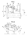
- Figs. 1 and 2 show a speed reduction mechanism in accordance with one embodiment of the present invention.
- a generally disc-shaped drive plate or drive member (first friction member) 12 is fixed to an end of a drive shaft 11 as a drive source such as a crankshaft of an internal combustion engine.
- a fixed plate or fixed member (second non-rotatably secured friction member) 13 is opposite the drive plate 12 and is fitted to a base member or the like.
- a rotor 14 as a frictional wheel is disposed between the drive plate 12 and the fixed plate 13, and frictionally contacts them.
- the rotor 14 is rotatably and oscillationally attached to a speed reduction rotary plate or rotary member 16 disposed between the drive plate 12 and the fixed plate 13 and rotatably supported by the drive shaft 11 through a bearing 15.
- the rotor 14 when the rotor 14 contacts the drive plate 12 at point A and contacts the fixed plate 13 at point C, the rotor 14 can be rotated around a rotary central portion or point B so that the positions of points A and C can be changed. Namely, the distance R1 from the central line O of the drive shaft 11 to point A, and the distance R3 from the central line O to contact point C can be changed where the distance between the central line O to point B is designated by R2.
- Fig. 2 showing the schematic construction of Fig. 1.
- the same constructive portions as those of Fig. 1 are designated by the same reference numerals.
- the drive plate 12 is rotated by angle ⁇
- point A is moved to point A2.
- the speed reduction rotary member 16 is rotated by angle ⁇ smaller than angle ⁇ , and point B is moved to point B1, and contact point C is also moved to contact point C1, where the angle between contact points C and C1 is designated by ⁇ .
- an outer sleeve 22 is press-fitted into a crankshaft 21 of an internal combustion engine as a drive source.
- a drive member (first friction member) 23 is pressed by a crank bolt 24 at an end of the outer sleeve 22 and is fixed to the crankshaft 21.
- the drive member 23 is approximately in the shape of a disc, and a frictional portion 25 approximately having an arc in cross section is annularly formed around the crankshaft 21 on a side of the drive member 23.
- a pulley groove portion 26 is formed in a peripheral portion of the drive member 23, and the speed reduction of the pulley groove portion 26 is not performed.
- a fixed member (second friction member) 28 fitted to the crankshaft 21 is fixed by a bolt 30 to a side wall of a cylinder block 27 through an error absorbing member 29 in a position opposite the drive member 23.
- the fixed member 28 is composed of a frictional portion 31 approximately having an arc in cross section, and a base portion 32, and a compression spring 33 is disposed between the frictional portion 31 and the base portion 32 such that the frictional portion 31 is biased towards the frictional portion 25.
- the frictional portions 31 and 25 are opposite each other such that these portions form a circular shape by continuously extending and connecting their arc shapes to each other.
- a rotor 34 is disposed as a frictional wheel approximately in the shape of a disc between the frictional portions 25 and 31.
- a peripheral portion 34a of the rotor 34 frictionally contacts the frictional portions 25 and 31, and this frictional contact generates a frictional force by the biasing force of the compression spring 33, thereby securing the transmission of the rotary drive force.
- a speed altering rotary member 35 is rotatably supported by the outer sleeve 22 through a bearing 36 between the drive member 23 and the fixed member 28.
- the rotor 34 is rotatably attached to the speed rotary member 35 through a bearing 37.
- Three rotors 34 are attached to the speed rotary member 35, and are spaced apart from each other by an equal angle in the circumferential direction around the crankshaft 21 as a center.
- a pulley groove portion 38 is formed in a peripheral portion of the speed rotary member 35, and an unillustrated belt is wound around the pulley groove portion 38, and is wound around an unillustrated pulley attached to an input shaft of an auxiliary apparatus.
- the fixed member 28 is arranged in a position in which the fixed member 28 is slightly separated from a side face of the cylinder block 27, which is called a misalignment in the following description.
- the misalignment is absorbed by the error absorbing member 29, and the fixed member 28 is fixed to the cylinder block 27.
- the error absorbing member 29 is composed of a cylinder 38 extending through the base portion 32 of the fixed member 28 and having a flange portion, and a pair of O-rings 39 disposed in the outer circumference of the cylinder 38 and pressing the base portion 32 therebetween.
- the drive member 23 is rotated by the rotary drive force of the crankshaft 21, and the speed of this rotation is reduced by the speed reduction mechanism mentioned above, and is then transmitted to the speed altering rotary member 35, and is further transmitted to an input shaft of the auxiliary apparatus through a belt. Accordingly, the rotation of the crankshaft 11 at a high speed is reduced and is transmitted to the auxiliary apparatus so that no high heat is generated in frictional elements of the auxiliary apparatus, etc., thereby improving the durability thereof.
- This speed reduction can be curvedly performed steplessly when the rotor 34 is rotated. Namely, when the number of rotations of the internal combustion engine exceeds a predetermined value at a high speed, the number of transmitted rotations of the auxiliary apparatus can be greatly reduced so as not to rotate the engine excessively.
- the speed reduction mechanism has a canti-lever structure
- the apparatus can be made compact so that the apparatus can be sufficiently disposed even in an engine room having a small space to be utilized.
- the speed reduction is performed by utilizing the rotor 34 as a frictional wheel, so that, even when the rotary drive force of the crankshaft 21 is slightly changed, this slight change can be absorbed by the frictional contact so as not to be transmitted to the belt, thereby preventing the deterioration of the durability of the belt due to such a slight change.
- the speed reduction mechanism is disposed in the crankshaft 21 as a drive shaft, but may be disposed in a driven shaft of an auxiliary apparatus, etc., in which case the operation is the same as the one mentioned in the above embodiment. Further, the speed reduction mechanism is used when the rotational speed of the crankshaft 21 of the internal combustion engine is reduced, but may be used in a place in which it is necessary to dispose the conventional speed reduction mechanism.
- the rotational speed of an internal combustion engine as a drive source is reduced and the rotational force thereof is transmitted to the speed altering rotary member, thereby transmitting the speed reduction rotation to a driven source such as an auxiliary apparatus. Accordingly, no high heat is generated in frictional elements of the auxiliary apparatus, etc., thereby improving the durability thereof.
- the apparatus can be made compact and be sufficiently disposed in a small engine room, etc., and, even when the rotary drive force is slightly changed, this slight change can be absorbed by frictional contact, thereby improving the durability of a belt.
- the disc-shaped rotor 34 is composed of a disc portion 41 having a peripheral portion 34a frictionally contacting the frictional portions 25 and 31, and a central shaft 43 for rotatably supporting the disc portion 41 through a bearing 42.
- the central shaft 43 of the disc-shaped rotor 34 is rotatably supported by a rotary holder 44 approximately having a cylindrical shape.
- a holding hole 45 for receiving and holding and storing the rotor 34 is formed in an approximately central portion of the rotary holder 44.
- the upper and lower ends of the central shaft 43 are fixed to the rotary holder 44 perpendicularly to the axis of the rotary holder 44.
- the rotary holder 44 is disposed in the speed altering rotary member 35 such that the axis of the rotary holder 44 is perpendicular to the radial direction of the speed rotary member 35.
- the rotary holder 44 is stored in a storing elongated hole portion 35a disposed to be perpendicular to the radial direction of the speed rotary member 35.
- Support shaft portions 44a and 44b integrally formed at both ends of the rotary holder 44 are rotatably held and fixed by a pair of fixing plates 47a and 47b therebetween through bearings 46.
- the rotary holder 44 for supporting the rotor 34 is disposed around the crankshaft 21 in the speed rotary member 35 by three ones at an equal angle in the circumferential direction, where two of the rotary holders are not illustrated in the figures.
- the above-mentioned distances R1 and R3 are freely changed by the oscillating movement of the rotor 34, thereby freely changing the speed reduction ratio ⁇ / ⁇ of the speed reduction mechanism.
- Fig. 6 shows the relation between the number of rotations of the internal combustion engine and the number of rotations of the speed reduction rotary member, which is the speed reduction characteristics when the rotor 34 is oscillated.
- linear line A is related to the case in which the speed reduction mechanism is not disposed.
- the reduction ratio ⁇ / ⁇ shows the characteristics illustrated by curve B.
- the speed rotary member is rotated to greatly reduce the number of rotations of the internal combustion engine and the rotational force of the speed rotary member can be transmitted to the auxiliary apparatus, thereby preventing an excessive rotation of the auxiliary apparatus.
- the speed rotary member can be rotated at a number of rotations larger than a predetermined one and this rotational force can be transmitted to the auxiliary apparatus so that the auxiliary apparatus can be sufficiently functioned.
- auxiliary apparatuses such as a compressor for air conditioner, alternator are unnecessarily operated at a high speed
- the internal combustion engine loses the horse power thereof due to such an unnecessary high speed operation.
- the rotational speed of the auxiliary apparatus is variably reduced so as not to excessively rotate the engine, so that the loss of the horse power of the internal combustion engine for rotating the auxiliary apparatus can be reduced. Accordingly, the output of the internal combustion engine can be increased by reducing the lost horse power thereof, and the fuel cost thereof can be reduced.
- disc-shaped rotor is oscillated such that, when one of both edges of disc-shaped rotor in the direction of the rotary central axis of the drive member approaches this rotary central axis, the other of the both edges of the rotor is moved away from the rotary central axis. Accordingly, the rotation of the internal combustion engine can be transmitted to the driven source such as the auxiliary apparatus with the speed reduction changed. Thus, no high heat is generated in frictional elements of the auxiliary apparatus, etc., thereby improving the durability thereof. Further, the fuel cost is reduced since the lost horse power of the internal combustion engine can be reduced. Further, even when the internal combustion engine can be rotated at a low speed, the auxiliary apparatus, etc., can be rotated at a number of rotations larger than a predetermined one, so that the auxiliary apparatus, etc., can be sufficiently functioned.
- a pair of pins 48a and 48b are disposed at both ends of the rotary holder 44.
- three elongated holes 50 are radially disposed in an intermediate portion of the speed altering rotary member 35 disposing the adjacent rotary holder 44 therein, and are spaced apart from each other at an equal angle around a crankshaft 21.
- a centrifugal weight 51 is slidably fitted into each of the elongated holes 50, and a cam plate 52 approximately in the shape of an isosceles triangle is fixed onto a face of the centrifugal weight 51 on the side of fixed member 28.
- a stopping plate 53 is fixed onto a face of the centrifugal weight 51 on the side of drive member 23.
- a pair of elongated holes 54a and 54b are disposed on right and left sides of the cam plate 52.
- the pin 48b of the rotary holder 44 is inserted into the one elongated hole 54b, and an unillustrated pin of adjacent another rotary holder which is not shown is inserted into the other elongated hole 54a.
- the centrifugal weight 51 is slid by the centrifugal force thereof towards the outer circumference of the speed rotary member 35 so that the pin 48b is pushed by the cam plate 52 fixed to the centrifugal weight 51 in the outer circumferential direction of the speed rotary member 35.
- the rotary holder 44 When the pin 48b is pushed in this outer circumferential direction, the rotary holder 44 is rotated in the outer circumferential direction as shown by arrow A in Fig. 8 since the rotary holder 44 is rotatably disposed in the speed rotary member 35, thereby oscillating the disc-shaped rotor 34.
- a pin 60 is disposed on a wall surface of the speed rotary member 35 in the inner circumference thereof, and a tension spring 55 is disposed between the pin 60 and the pin 48b of the rotary holder 44, so that the rotary holder 44 is biased at any time in a direction opposite the direction of arrow A.
- the rotary holder 44 is rotated by the centrifugal weight 51 and the tension spring 55 in the direction of arrow A or the reverse direction thereof, thereby oscillating the disc-shaped rotor 34.
- the distances R1 and R3 mentioned above can be freely changed by the oscillation of the rotor 34, so that the speed reduction ratio of the speed reduction mechanism can be freely changed.
- the centrifugal weight 51, cam plate 52 and stopping plate 53 constitute an oscillating means 61 as a whole.
- the rotor 34 is disposed in the speed rotary member 35 in parallel to the axis of the crankshaft 21, but may be disposed in a state in which the rotor 34 is rotated by a slight angle ⁇ such as an angle less than 1 degree with respect to the axial direction of the crankshaft, as shown in Fig. 13. In such a case, the rotor 34 starts to be more smoothly oscillated when the speed reduction mechanism is started.
- the disc-shaped rotor is oscillated by an oscillating means in accordance with the rotational speed of a drive source such as an internal combustion engine so that the rotation of the drive source can be transmitted to a driven source such as an auxiliary apparatus with the speed reduction ratio changed.
- a drive source such as an internal combustion engine
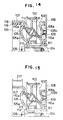
- Fig. 12 shows another embodiment of the present invention.
- a stepless speed change mechanism 103 is disposed in a power transmission system from a crankshaft 101 of an internal combustion engine to a pulley 102 for driving a stepless speed change auxiliary apparatus.
- An outer sleeve 104 is press-fitted into the crankshaft 101, and drive member (first friction member) 105 is pressed by a crank bolt 106 towards an end of the outer sleeve 104, and is fixed to the crankshaft 101.
- the drive member 105 is generally in the shape of a disc, and a frictional portion 105a approximately having an arc in cross section is annularly formed on a side of the drive member 105 around the crankshaft 101 as a center.
- a hub portion 107 approximately having a cylindrical shape is formed in a peripheral portion of the drive member 105.
- a fixed member (second friction member) 108 is fitted into the crankshaft 101, and is fixed to an unillustrated cylinder block in a position opposite the drive member 105.
- the fixed member 108 is composed of a frictional portion 108a approximately having an arc in cross section and a base portion 108b, and a belleville spring 109 is disposed between the frictional portion 108a and the base portion 108b so that the frictional portion 108a is biased by the belleville spring 109 towards the frictional portion 105a.
- the frictional portions 105a and 108a are arranged to be opposite each other such that they form a circular shape by extending and connecting their arc shapes to each other.
- a generally disc-shaped rotor 110 is disposed as a frictional wheel between the frictional portions 105a and 108a.
- a peripheral portion 110a of the rotor 110 frictionally contacts the frictional portions 105a and 108a. This frictional contact generates a frictional force by the biasing force of the belleville spring 109, thereby securing the transmission of the rotary drive force.
- a speed altering rotary member 111 is rotatably supported by the outer sleeve 104 through a bearing 112 between the drive member 105 and the fixed member 108.
- the rotor 110 is rotatably attached to the speed rotary member 111 through a bearing 113.
- the rotor 110 is oscillationally attached to the speed rotary member 111 such that, when one of both edges of the rotor 110 in the direction of the central rotary axis of the crankshaft 101 approaches the crankshaft 101, the other edge of the rotor 110 is moved away from the crankshaft 101.
- the rotor 110 is oscillated by an oscillating mechanism which is not shown.
- a pulley 102 for driving a stepless speed change auxiliary apparatus is integrally formed in a peripheral portion of the speed rotary member 111, and an unillustrated belt is wound around the pulley 102, and is also wound around an unillustrated pulley attached to an input shaft of the auxiliary apparatus.
- a ring 114 is press-fitted into the outer circumference of the hub portion 107 of the drive member 105, and an elastic member 115 made of natural rubber, synthetic rubber, etc., is disposed on the outer circumference of the press-fitted ring 114.
- a cylindrical oscillation-restricting mass 116 is fitted onto the outer circumference of the elastic member 115.
- the rotor 110 When the drive member 105 is rotated by the rotary drive force of the crankshaft 101, the rotor 110 is rotated around itself and is simultaneously revoluted around the central axis of the crankshaft 101, since the rotor 110 contacts both the rotating drive member 105 and the resting fixed member 108.
- the speed rotary member 111 is rotated around the central axis of the crankshaft 101 by the revolution of the rotor 110.
- the rotor 110 is oscillated by an oscillating mechanism in accordance with the rotational speed of the crankshaft 101. Accordingly, the rotational speed of the crankshaft 101 is steplessly changed by the stepless speed change mechanism 103, and the rotation of the crankshaft 101 is transmitted from the pulley 102 through a belt to the stepless speed change auxiliary apparatus.
- the oscillation-restricting mass 116 is disposed in the drive member 105 through the elastic member 115, the torsional oscillation of the crankshaft 101 is transmitted to the elastic member 115 and the oscillation-restricting mass 116, thereby greatly oscillating the elastic member 115 and the oscillation-restricting mass 116. Therefore, the torsional angle of the crankshaft 101 is less than 0.2° until the rotational speed of the internal combustion engine reaches 6000 rpm so that the torsional oscillation is reduced. Accordingly, since the torsional oscillation is reduced, the noise can be restricted and the crankshaft 101 is not damaged by the fatigue thereof, and the crankshaft 101 is not untightened.
- a pulley having the function of an oscillation-restricting mass may be used instead of the oscillation-restricting mass, thereby obtaining the function of the pulley having the same rotational speed as the one of the crankshaft and the speed-reduction function of the pulley 102.
- a pulley 117 having a corrugated shape in cross section has a function of the oscillation-restricting mass, and is disposed to drive the auxiliary apparatus directly connected to the crankshaft, and is fitted onto the outer circumference of the elastic member 115.
- a ring 118 is press-fitted into the inner circumference of the hub portion 107 of the drive member 105, and an elastic member 119 is disposed in the inner circumference of the press-fitted ring 118, and an oscillation-restricting mass 120 is fitted into the inner circumference of the elastic member 119.
- the torsional oscillation of the crankshaft 101 can be reduced by the elastic members 115 and 119, the pulley 117 and the oscillation-restricting mass 120 as in the embodiment shown in Fig. 12.
- Fig. 15 shows another embodiment of the present invention.
- a pulley 217 directly connected to a crankshaft and driving an auxiliary apparatus is attached to an outer circumference of the hub portion 107 of the drive member 105 mentioned above.
- the rotational speed of the pulley 217 is not reduced, and the pulley 217 is rotated at the same speed as the one of the crankshaft. Accordingly, such a pulley 217 may be used when it is necessary to operate the auxiliary apparatus without reducing the rotational speed of the crankshaft, depending on the function of the engine and the kind of the auxiliary apparatus.
- auxiliary drive apparatus of the present invention when used as an auxiliary drive apparatus for an automobile such as a power pump, air compressor, or alternator, etc., which does not need to be operated at a speed higher than a predetermined speed, the rotational speed of the auxiliary drive apparatus can be maintained at the predetermined speed even when the number of rotations of the internal combustion engine is increased.
- the number of rotations of an auxiliary drive apparatus such as a water pump can be increased in accordance with the increase of the number of rotations of the engine since it is important from the view point of the engine cooling to rotate the auxiliary apparatus in proportion to the increase of the number of rotations of the engine.
- the auxiliary drive apparatus can be made compact and the structure thereof can be simplified.
Landscapes
- Engineering & Computer Science (AREA)
- General Engineering & Computer Science (AREA)
- Mechanical Engineering (AREA)
- Transmissions By Endless Flexible Members (AREA)
- Supercharger (AREA)
Claims (11)
- Mécanisme de réduction de la vitesse pour un appareil d'entrainement des auxiliaires dans un moteur à combustion interne, comportant:
un premier élément de friction (12; 105) qui a approximativement la forme d'un disque et, en section droite, la forme d'un arc, et qui est formé annulairement autour d'un axe de rotation;
un second élément de friction (13), fixé sans liberté de rotation, qui a approximativement la forme d'un disque et, en section droite, la forme d'un arc, formé autour d'un axe central, ledit second élément de friction étant disposé en face dudit premier élément de friction;
un élément rotatif (35) modifiant la vitesse, relié à des moyens qui sont prévus pour fournir un mouvement de rotation et comprenant au moins un rotor (34) qui est en liaison, par friction, avec ledit premier et avec ledit second éléments de friction, ce par quoi l'axe de rotation dudit rotor peut être modifié;
un support (44) pour ledit rotor (34), ledit support étant disposé, dans ledit élément rotatif (35) modifiant la vitesse, de façon telle que l'axe du support rotatif soit perpendiculaire à la direction radiale de l'élément rotatif (35) modifiant la vitesse; et
des moyens pour relier ledit premier élément de friction à une source d'entrainement;
mécanisme caractérisé par le fait que ledit élément de rotation (35) modifiant la vitesse comporte:
un élément de commande (48b), en forme de tenon, venant en saillie depuis ledit support (44), ledit élément de commande en forme de tenon pouvant se déplacer sur un angle variable, par rapport audit élément rotatif (35) modifiant la vitesse, pour faire tourner ledit support (44) autour de l'axe de rotation dudit support pour modifier la position dudit axe de rotation dudit rotor (34); et
une masse centrifuge (51) montée, mobile, sur ledit élément rotatif (35) modifiant la vitesse et reliée de façon à déplacer ledit élément de commande (48b) en forme de tenon. - Mécanisme de réduction de vitesse de la revendication 1, dans lequel une première poulie (38) est directement disposée sur une circonférence extérieure dudit élément rotatif (35) modifiant la vitesse pour en fournir le mouvement de rotation.
- Mécanisme de réduction de vitesse des revendications 1 ou 2, dans lequel ledit élément rotatif (35) modifiant la vitesse est un plateau circulaire.
- Mécanisme de réduction de vitesse des revendications 1 ou 2, dans lequel ledit élément rotatif (35) modifiant la vitesse présente une fente (50) dans lequel ladite masse centrifuge (51) est placée avec liberté de coulissement.
- Mécanisme de réduction de vitesse de la revendication 4, dans lequel un ressort (55) est attaché audit élément de commande (48b) en forme de tenon et à ladite masse centrifuge pour positionner, avec liberté de coulissement, ladite masse centrifuge le long de ladite fente.
- Mécanisme de réduction de vitesse de la revendication 5, dans lequel une came (52) est située sur ladite masse centrifuge et est attachée audit ressort (55).
- Mécanisme de réduction de vitesse de la revendication 6, dans lequel ladite came (52) est approximativement un triangle isocèle.
- Mécanisme de réduction de vitesse de la revendication 1, dans lequel ledit rotor (34) est disposé sous un angle inférieur à un degré par rapport à l'axe de rotation de ladite source d'entrainement.
- Mécanisme de réduction de vitesse de la revendication 1, qui comporte en outre des moyens (33) pour contraindre ledit second élément de friction, fixé sans liberté de rotation, en direction dudit rotor.
- Mécanisme de réduction de vitesse de la revendication 1 , qui comporte en outre des moyens formant masse (116) attachés à une circonférence extérieure dudit premier élément de friction (105) par l'intermédiaire d'un élément élastique (115) pour limiter l'oscillation dudit premier élément de friction.
- Mécanisme de réduction de vitesse de la revendication 1 , qui comporte en outre une seconde poulie (117) directement disposée sur une circonférence extérieure dudit premier élément de friction (105).
Applications Claiming Priority (8)
| Application Number | Priority Date | Filing Date | Title |
|---|---|---|---|
| JP53181/87 | 1987-03-10 | ||
| JP5318187A JPS63219955A (ja) | 1987-03-10 | 1987-03-10 | 減速機構 |
| JP6105287A JPS63231052A (ja) | 1987-03-18 | 1987-03-18 | 減速機構 |
| JP61052/87 | 1987-03-18 | ||
| JP71892/87 | 1987-03-27 | ||
| JP7189287A JPS63243561A (ja) | 1987-03-27 | 1987-03-27 | 内燃機関の補機駆動装置 |
| JP23497287A JPS6479463A (en) | 1987-09-21 | 1987-09-21 | Auxiliary machine driving device for internal combustion engine |
| JP234972/87 | 1987-09-21 |
Publications (2)
| Publication Number | Publication Date |
|---|---|
| EP0283855A1 EP0283855A1 (fr) | 1988-09-28 |
| EP0283855B1 true EP0283855B1 (fr) | 1992-06-10 |
Family
ID=27462872
Family Applications (1)
| Application Number | Title | Priority Date | Filing Date |
|---|---|---|---|
| EP88103734A Expired - Lifetime EP0283855B1 (fr) | 1987-03-10 | 1988-03-09 | Appareil d'entraînement d'auxiliaires |
Country Status (3)
| Country | Link |
|---|---|
| US (1) | US4850234A (fr) |
| EP (1) | EP0283855B1 (fr) |
| DE (1) | DE3871831T2 (fr) |
Families Citing this family (4)
| Publication number | Priority date | Publication date | Assignee | Title |
|---|---|---|---|---|
| US5188002A (en) * | 1988-07-25 | 1993-02-23 | Woco Franz-Josef Wolf & Co. | Torsional vibration damper |
| DE19817955A1 (de) * | 1998-04-22 | 1999-10-28 | Schaeffler Waelzlager Ohg | Wälzgetriebe, insbesondere Toroidgetriebe |
| DE102008022306A1 (de) | 2008-05-06 | 2009-11-12 | Schaeffler Kg | Reibradgetriebe, insbesondere Toroidgetriebe, und Reibrad hierfür |
| CA2945465A1 (fr) | 2014-04-14 | 2015-10-22 | Kawasaki Jukogyo Kabushiki Kaisha | Transmission a variation continue toroidale |
Citations (3)
| Publication number | Priority date | Publication date | Assignee | Title |
|---|---|---|---|---|
| US158158A (en) * | 1874-12-22 | Improvement in perforators for telegraph-paper | ||
| DE2139600A1 (de) * | 1970-08-17 | 1972-02-24 | General Motors Corp., Detroit, Mich. (V.StA.) | Von der Antriebsmaschine eines Fahrzeugs abgeleiteter Antrieb für dessen Hilfsgeräte |
| DE3428894A1 (de) * | 1984-08-04 | 1986-02-13 | M.A.N. Maschinenfabrik Augsburg-Nürnberg AG, 8500 Nürnberg | Schwingungsdaempfer zur daempfung rotierender massen |
Family Cites Families (14)
| Publication number | Priority date | Publication date | Assignee | Title |
|---|---|---|---|---|
| US705209A (en) * | 1900-11-24 | 1902-07-22 | Walter E Crane | Variable-speed device. |
| US1175677A (en) * | 1914-10-24 | 1916-03-14 | Roderick Mcclure | Power-transmitting device. |
| AT100369B (de) * | 1921-11-30 | 1925-07-10 | Richard Ing Erban | Reibungsgetriebe. |
| US1847553A (en) * | 1930-05-15 | 1932-03-01 | Aeromarine Plane & Motor Compa | Variable speed transmission |
| US2101844A (en) * | 1935-08-09 | 1937-12-14 | Fraser George Holt | Speed reducer and other transmission |
| US2861472A (en) * | 1953-02-10 | 1958-11-25 | Us Rubber Co | Torsional vibration damper |
| CH345514A (de) * | 1956-07-07 | 1960-03-31 | Ernst Kopp Jean | Stufenlos regelbares Reibungsgetriebe |
| US2977819A (en) * | 1959-01-26 | 1961-04-04 | Fred L Haushalter | Vibration damper |
| GB961674A (en) * | 1960-10-21 | 1964-06-24 | Borg Warner | Planetary gear accessory drive |
| US3596524A (en) * | 1970-01-20 | 1971-08-03 | Trw Inc | Engine accessory drive system |
| US4257495A (en) * | 1978-05-10 | 1981-03-24 | National Research Development Corporation | Damping device |
| GB2035481B (en) * | 1978-11-16 | 1983-01-19 | Cam Gears Ltd | Speed control systems |
| JPS61211552A (ja) * | 1985-03-13 | 1986-09-19 | Toyota Motor Corp | 車輌のクランクダンパプ−リ構造 |
| US4794816A (en) * | 1985-10-15 | 1989-01-03 | Tokai Rubber Industries, Ltd. | Dual-type damper device |
-
1988
- 1988-03-09 EP EP88103734A patent/EP0283855B1/fr not_active Expired - Lifetime
- 1988-03-09 DE DE8888103734T patent/DE3871831T2/de not_active Expired - Lifetime
- 1988-03-10 US US07/166,349 patent/US4850234A/en not_active Expired - Fee Related
Patent Citations (3)
| Publication number | Priority date | Publication date | Assignee | Title |
|---|---|---|---|---|
| US158158A (en) * | 1874-12-22 | Improvement in perforators for telegraph-paper | ||
| DE2139600A1 (de) * | 1970-08-17 | 1972-02-24 | General Motors Corp., Detroit, Mich. (V.StA.) | Von der Antriebsmaschine eines Fahrzeugs abgeleiteter Antrieb für dessen Hilfsgeräte |
| DE3428894A1 (de) * | 1984-08-04 | 1986-02-13 | M.A.N. Maschinenfabrik Augsburg-Nürnberg AG, 8500 Nürnberg | Schwingungsdaempfer zur daempfung rotierender massen |
Also Published As
| Publication number | Publication date |
|---|---|
| DE3871831D1 (de) | 1992-07-16 |
| EP0283855A1 (fr) | 1988-09-28 |
| DE3871831T2 (de) | 1992-12-10 |
| US4850234A (en) | 1989-07-25 |
Similar Documents
| Publication | Publication Date | Title |
|---|---|---|
| CN100513816C (zh) | 曲轴分离器 | |
| US6270436B1 (en) | Continuously variable transmission | |
| EP0475942A1 (fr) | Systeme de transmission a reglage continu | |
| KR0185772B1 (ko) | 무단변속기 | |
| US5368529A (en) | Toroidal type continuously variable transmission | |
| US4617004A (en) | Pulley strap drive | |
| US4875894A (en) | Continuously variable transmission | |
| CA2007851A1 (fr) | Transmission a variation continue, avec poulies de diametre variable reagissant aux forces axiales | |
| EP0283855B1 (fr) | Appareil d'entraînement d'auxiliaires | |
| KR100494886B1 (ko) | 진동감쇠장치 | |
| JP3914307B2 (ja) | 無段変速可能な巻掛け式変速機 | |
| WO2002008639A1 (fr) | Coupleur cvt a couronnes d'entrainement de courroie | |
| AU2001273547A1 (en) | Belt drive ring CVT coupler | |
| US6422371B1 (en) | Centrifugal friction clutch for automatic transmission | |
| JPS5839868A (ja) | ベルト式自動変速機 | |
| JP2001200911A (ja) | 被固定部材の軸方向位置決め構造 | |
| KR100263777B1 (ko) | 풀리 | |
| JP3648383B2 (ja) | 可変径プーリ | |
| JP3988213B2 (ja) | 可変径プーリ | |
| JPH08178003A (ja) | Vベルト式自動変速装置 | |
| JP3727472B2 (ja) | 補機駆動装置 | |
| US4771875A (en) | Multi element rotor for a centrifugal clutch | |
| JP3623334B2 (ja) | 可変径プーリ及びこれを含む無段変速機 | |
| RU1805252C (ru) | Клиноременный вариатор | |
| SU1402740A2 (ru) | Фрикционна передача |
Legal Events
| Date | Code | Title | Description |
|---|---|---|---|
| PUAI | Public reference made under article 153(3) epc to a published international application that has entered the european phase |
Free format text: ORIGINAL CODE: 0009012 |
|
| 17P | Request for examination filed |
Effective date: 19880309 |
|
| AK | Designated contracting states |
Kind code of ref document: A1 Designated state(s): DE FR GB |
|
| 17Q | First examination report despatched |
Effective date: 19900118 |
|
| GRAA | (expected) grant |
Free format text: ORIGINAL CODE: 0009210 |
|
| AK | Designated contracting states |
Kind code of ref document: B1 Designated state(s): DE FR GB |
|
| REF | Corresponds to: |
Ref document number: 3871831 Country of ref document: DE Date of ref document: 19920716 |
|
| ET | Fr: translation filed | ||
| PG25 | Lapsed in a contracting state [announced via postgrant information from national office to epo] |
Ref country code: GB Effective date: 19930309 |
|
| PLBE | No opposition filed within time limit |
Free format text: ORIGINAL CODE: 0009261 |
|
| STAA | Information on the status of an ep patent application or granted ep patent |
Free format text: STATUS: NO OPPOSITION FILED WITHIN TIME LIMIT |
|
| 26N | No opposition filed | ||
| GBPC | Gb: european patent ceased through non-payment of renewal fee |
Effective date: 19930309 |
|
| PG25 | Lapsed in a contracting state [announced via postgrant information from national office to epo] |
Ref country code: FR Effective date: 19931130 |
|
| PG25 | Lapsed in a contracting state [announced via postgrant information from national office to epo] |
Ref country code: DE Effective date: 19931201 |
|
| REG | Reference to a national code |
Ref country code: FR Ref legal event code: ST |