EP0283901A1 - Brûleur à gaz à flamme plate - Google Patents
Brûleur à gaz à flamme plate Download PDFInfo
- Publication number
- EP0283901A1 EP0283901A1 EP88104068A EP88104068A EP0283901A1 EP 0283901 A1 EP0283901 A1 EP 0283901A1 EP 88104068 A EP88104068 A EP 88104068A EP 88104068 A EP88104068 A EP 88104068A EP 0283901 A1 EP0283901 A1 EP 0283901A1
- Authority
- EP
- European Patent Office
- Prior art keywords
- burner
- gas
- hollow body
- plate
- wall
- Prior art date
- Legal status (The legal status is an assumption and is not a legal conclusion. Google has not performed a legal analysis and makes no representation as to the accuracy of the status listed.)
- Granted
Links
Images


Classifications
-
- F—MECHANICAL ENGINEERING; LIGHTING; HEATING; WEAPONS; BLASTING
- F23—COMBUSTION APPARATUS; COMBUSTION PROCESSES
- F23D—BURNERS
- F23D14/00—Burners for combustion of a gas, e.g. of a gas stored under pressure as a liquid
- F23D14/46—Details
- F23D14/62—Mixing devices; Mixing tubes
-
- F—MECHANICAL ENGINEERING; LIGHTING; HEATING; WEAPONS; BLASTING
- F23—COMBUSTION APPARATUS; COMBUSTION PROCESSES
- F23D—BURNERS
- F23D14/00—Burners for combustion of a gas, e.g. of a gas stored under pressure as a liquid
- F23D14/02—Premix gas burners, i.e. in which gaseous fuel is mixed with combustion air upstream of the combustion zone
-
- F—MECHANICAL ENGINEERING; LIGHTING; HEATING; WEAPONS; BLASTING
- F23—COMBUSTION APPARATUS; COMBUSTION PROCESSES
- F23D—BURNERS
- F23D14/00—Burners for combustion of a gas, e.g. of a gas stored under pressure as a liquid
- F23D14/34—Burners specially adapted for use with means for pressurising the gaseous fuel or the combustion air
- F23D14/36—Burners specially adapted for use with means for pressurising the gaseous fuel or the combustion air in which the compressor and burner form a single unit
-
- F—MECHANICAL ENGINEERING; LIGHTING; HEATING; WEAPONS; BLASTING
- F23—COMBUSTION APPARATUS; COMBUSTION PROCESSES
- F23D—BURNERS
- F23D14/00—Burners for combustion of a gas, e.g. of a gas stored under pressure as a liquid
- F23D14/46—Details
- F23D14/48—Nozzles
- F23D14/58—Nozzles characterised by the shape or arrangement of the outlet or outlets from the nozzle, e.g. of annular configuration
-
- F—MECHANICAL ENGINEERING; LIGHTING; HEATING; WEAPONS; BLASTING
- F23—COMBUSTION APPARATUS; COMBUSTION PROCESSES
- F23D—BURNERS
- F23D14/00—Burners for combustion of a gas, e.g. of a gas stored under pressure as a liquid
- F23D14/46—Details
- F23D14/70—Baffles or like flow-disturbing devices
-
- F—MECHANICAL ENGINEERING; LIGHTING; HEATING; WEAPONS; BLASTING
- F23—COMBUSTION APPARATUS; COMBUSTION PROCESSES
- F23D—BURNERS
- F23D14/00—Burners for combustion of a gas, e.g. of a gas stored under pressure as a liquid
- F23D14/46—Details
- F23D14/72—Safety devices, e.g. operative in case of failure of gas supply
- F23D14/78—Cooling burner parts
Definitions
- the invention relates to a gas surface burner for heating boilers according to the preamble of the main claim.
- Such a gas surface burner is known from DE-A-35 03 553.
- a short-burning surface flame standing in layers above the outflow surface can be generated, but it has been observed that, particularly in the peripheral edge region of the poorly burning flame, protruding, i.e. longer-burning flame regions result, which also have negative effects on the measured NOX values to lead.
- protruding i.e. longer-burning flame regions result, which also have negative effects on the measured NOX values to lead.
- Another relevant prior art is represented by the following documents: US-A-1,582,634, DE-A-18 06 936 and DE-A-31 13 416.
- the invention is based on the object, starting from a gas surface burner of the type mentioned, to improve it in such a way that in the form of a surface flame directly behind the opening of the mixing chamber with a relatively low temperature and thus NOX-reducing burning gas-air mixture should also burn in the peripheral edge areas under these conditions.
- this relatively simple measure of arranging a ring-like or frame-like edge cover can achieve that the peripheral edge regions burn largely in the manner of a surface flame, that is to say no protruding flame regions arise and the low NOX values to be aimed at can be better achieved .
- a type of hot air or hot gas recirculation will presumably result in this area, whereby the recirculating hot gases also result in at least similar conditions for the edge areas of the surface flame as they do in the more inner areas Areas of the surface flame.
- the edge covering in such a way that it is provided with a peripheral web on the burner side which extends perpendicular to the surface of the edge cover and which is provided with inflow openings.
- the opening cross-section of the ring-shaped or frame-shaped cover corresponds to the flame-effective cross-section of the surface, i.e. the inner opening edge of the edge cover runs flush with the outer peripheral edge of the flame-effective gas outflow surface, which is either structured in a lattice-like manner can, but which can also consist of a large number of relatively small individual holes.
- the holes located under the opening edge contour have approximately the same distance from one another and the hole density in the region of the opening edge contour corresponds approximately to the hole density on the entire perforated plate.
- the gas supply connection on the box-shaped gas supply housing which is closed except for a necessary edge area with the burner plate, is arranged centrally for the most uniform gas supply distribution under the burner plate, the mouth end being provided with a perforated closure plate and openings arranged in the side wall of the mouth end are whose diameter is larger than that of the holes in the closure plate.
- the easiest way to meet the requirement for equidistant spacing of the holes under the opening edge of the edge cover is that the holes of the burner plate are arranged in the form of a square grid, which, however, presupposes that the flame-retardant surface of the burner plate is also square and the outermost four rows of holes below that Edge of the corresponding square edge cover.
- the holes of the burner plate must have a relatively small diameter, which is of the order of about 1 to 2.5 mm. In order to be able to make such smaller-diameter holes in the plate with as little effort as possible, only punching out is possible.
- the burner plate must have a sufficient thickness in view of the temperature load in order to avoid warping of the plate. For this reason, the burner plate is formed from at least two spot-welded plate lamellae, the total thickness of which is greater than the diameter of the holes. This design of the burner plate means that its individual lamellae are accessible to a punching process for making the holes, which are then simply placed one on top of the other in alignment with the punched holes and spot welded.
- the burner chamber is designed as a hollow body
- this configuration ensures that every area of the burner plate, including the gas inflow channels, can be cooled.
- This training also makes manufacturing of such a burner is facilitated insofar as the hollow body can be easily assembled from two suitably perforated and pre-embossed shells, it being understood that all of the assembly points must be gastight and liquid-tight.
- a practical embodiment of such a gas burning device can consist in that the gas inflow channels are designed in the form of inserted tubes which extend from one wall to the other wall of the hollow body. It is readily possible to arrange the tubes inserted into the hollow body in a gas- and liquid-tight manner, at least on the flame side, projecting beyond the wall of the hollow body in question.
- ring-shaped, outward bends are expediently provided in the two hollow body walls, which can be easily formed when the respective shell is cut and pressed.
- the gas inflow channels in the form of wall impressions of the hollow body wall on the gas supply side and to connect the two walls of the hollow body around the gas outflow openings in a gas-tight and liquid-tight manner, which will be explained in more detail and where there is a possibility of to establish the connection with a correspondingly dimensioned annular spot welding electrode around the respective outflow opening.
- the embossed wall of the hollow body then represents itself similar to a waffle iron, whereby it must of course be ensured that the remaining cavity can be flowed through from the supply to the return connection.
- it can advantageously also be ensured during the pressing process of the flame-side shell that ring-shaped offsets directed towards the flame side arise around the gas outflow openings.
- the design principle of a coolable burner plate and its double-shell design also has the advantage of being able to dimension the sheet metal blanks larger and to keep the peripheral areas around free of gas outflow openings, the hole-free edges of the hollow body then being formed perpendicular to the burner plate surface to form a coolable peripheral wall limitation of the perforated burner plate .
- a water-cooled shaft wall is thus created around and formed by the burner plate itself, which is also advantageous in terms of NOx reduction.
- the aforementioned cover ring can be used here, but does not have to be provided.
- This embodiment can also have an advantageous further development in that one or the other wall of the hollow body, which extends perpendicular to the burner plate surface, is dimensioned longer than the other and in the projecting wall part, which is therefore no longer water-cooled, can flow through at least one gas, the free cross section heat exchanger approximately covering the burner plate at a distance above the burner plate and the short burner shaft together form a water-cooled element, so it is advantageously also easily possible to integrate a suitable heat exchanger without problems, for which the burner plate, so to speak, formed into a pot also forms the holder.
- the gas surface burner consists of a mixing tube 14 provided with a blower connection with a central gas supply tube 13 which has perforations 16 in the area of the mixing tube 14 so that the gas can flow out there and get in with the air supplied by the blower rotor 15 can mix for which the mixing tube in the area of the blower housing 11 is provided with corresponding air inlet slots (not shown).
- This mixing tube 14 is expediently arranged axially adjustable in the blower housing 11, which - as can be seen - is advantageously designed as a flat chamber 12.
- the gas mixing tube 14 opens into a mixing chamber 5 of relatively large cross-section, which is closed on the outflow side with a suitable perforated plate or a grille, which forms the flame-effective surface 1.
- the ring or frame-shaped edge cover 2 is arranged in its peripheral edge region, adapted to the cross-sectional shape of the surface, the opening thereof tion cross section 3 corresponds to the flame-retardant cross section of the surface 1. If this is a simple washer, it is of course fixed at the desired distance by appropriate holding elements (not shown).
- the edge cover on the blower side is provided with a circumferential web 4 which extends perpendicular to the plane of the edge cover 2.
- Either a circumferential gap 6 can be provided between the mixing chamber 5 and the circumferential web 4, but care must be taken that this recirculating hot gas 6 can flow into this circumferential gap 6, as indicated below with a dashed arrow.
- the circumferential web 4 is advantageously provided with openings 7, so that hot gas can recirculate through these openings 7 from the combustion chamber 17 and then flow out again through the edge regions of the opening cross section 3 of the cover 2. This recirculating hot gas seems to create conditions for the edge areas of the flame that are automatically given for the flame areas located further inward, which in a way support each other.
- the circumferential web 4 is provided with a heat-insulating enclosure 8, for example made of ceramic fiber material or the like, which prevents heat radiation from the circumferential web 4.
- the blower-side bottom 9 of the mixing chamber 5 is made of heat-insulating material of the same type, this material being arranged directly on the blower housing 11, which forms a flat chamber 12, in which the blower rotor 15 with a seio motor 10 is eccentrically arranged Mixing chamber 5 leading mixing tube 14 is arranged.
- the openings 7 can be more or less large and arranged in a more or less dense distribution on the circumferential web 4, which need not necessarily be circular holes as shown, but can also be slots or the like. Openings.
- Small axially adjustable guide webs which impart swirl to the gas-air mixture can be arranged within the axially adjustable mixing tube, which then result in a gas for the mediated swirl distribute in the mixing chamber 5 to weaken a massive direct flow to the center area of the surface 1. Possibly. can also be arranged at the closed end of the gas supply pipe in the mixing chamber 5, as indicated by dashed lines, there a perforated shield.
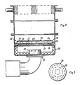
- the surface burner consists of a box-shaped gas supply housing 212 with gas supply connection 27 and perforated burner plate 21 in association, as shown, wherein according to the embodiment, the gas supply housing 212 forms the lower part of a small heat exchanger arranged above it, which does not require any further explanation here.
- the whole structure can practically be viewed as a small boiler.
- the cross section of the gas supply housing 212 and thus also of the attached heating boiler is square according to the exemplary embodiment in FIG. 2, which is not binding, ie the whole could also have a circular cross section.
- the annular or frame-shaped edge cover 22 is arranged over its edge regions, adapted to the cross-sectional shape of the burner plate 21, the opening cross section 23 of which corresponds to the flame-retardant surface of the perforated burner plate 21, ie the outermost holes 25 of the burner plate 21 are located under the opening edge 24 of the edge cover 22, which is provided with lateral openings 213 in the formation or profiling, for example, for the recirculation of hot gases from the region outside the edge cover profile.
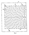
- the outer holes 25 of the burner plate 21 located under the opening edge 24 of the edge cover 22 are, as shown in FIG. 4, arranged at the same or approximately the same distance from one another, the hole density of the burner plate 21 in the region below the opening edge 24 being equal or approximately the hole density of the entire burner plate 21 is the same.
- This arrangement and assignment of the holes 25 would be easiest to implement if the holes 25 of the burner plate 21 were arranged in the form of a square grid. If, in this case, the burner plate were punched out in a circle, the condition of equidistant spacing of the holes under the opening edge 24 and the requirement for approximately the same hole density in the edge region would no longer be met.
- the mouth end of the gas supply connection 27 is arranged centrally below the burner plate, the mouth end 26 being provided with a closure plate 29 provided with holes 28 (FIG. 3), with openings 211 in the side wall 210 of the mouth end 26 all around are arranged, the diameter of which is larger than that of the holes 28 in the closure plate. If these lateral openings 211 were not present, there would be a preferred flow against the center area of the burner plate 21, which would, however, prevent the formation of a surface-burning flame.
- the burner plate 21 is formed from at least two spot-welded plate plates 21 ⁇ , the overall thickness of which is greater than the diameter of the holes 25.
- the thickness of the two plate plates 21 ⁇ 2.5 mm and can therefore still be punched with respect to the holes 25 if, for example, they also have a diameter of 2.5 mm. Due to the aligned assembly and spot welding of the two plate lamellae 21 ⁇ , the burner plate 21 is then sufficiently stable against thermal distortions. 0.5 to 4 gas mixture through openings are preferably provided per cm 2 of burner area.
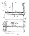
- the burner also consists of a gas supply housing 318 with a gas connection 319 and with a multiplicity of gas outflow openings which are arranged uniformly distributed in a coolable burner plate 31 which closes the housing 318.
- the burner plate 31 is designed as a hollow body 32 and is provided with supply and return connections 33, 34, the gas inflow channels 36 leading to the gas outflow openings 35 of the plate 31 being arranged in the hollow body 32, the walls of which 37 separate the interior of the hollow body 32 from the channels 36, which means nothing else that all areas of the burner plate 31 are directly accessible from the cooling medium.
- the gas inflow channels 36 are designed in the form of gas and liquid-tight tubes 38, which extend from one wall 32 Wand to the other wall 32 ⁇ of the hollow body 32 and, in a preferred embodiment, at least on the flame side via the wall 32 ⁇ of the hollow body 32 are outstandingly arranged.
- the tubes 38 are, as can be seen from the cutting area in FIG. 1, in annular, outwardly directed crimps 310 of the two hollow body walls 32 ⁇ , 32 ⁇ .
- Fig. 7 represents only a portion of the burner plate.
- the gas inflow channels 36 are designed in the form of wall impressions 39 of the gas supply-side hollow body wall 32 ⁇ , the two walls 32 ⁇ , 32 ⁇ of the hollow body 32 being connected to one another in a gas-tight and liquid-tight manner around the gas outflow openings 35.
- the manufacture of such a burning device is reduced to simple sheet metal cutting and punching or embossing processes.
- the wall impressions 39 in the region of the circumferential edges to be set vertically must of course also be eliminated there, like the tubes 38.
- FIG. 5 is preferred, in which the hollow body is formed from two shells and that of the gas outflow openings 35 kept free edges 312 of the hollow body 32 to form a coolable peripheral wall 313 of the perforated burner plate 31 perpendicular to the burner plate surface 314.
- the entire burner plate is shaped into a pot-like structure, the side walls of which can also be cooled directly in the area of the flame front.
- Corresponding embossments 320 in the area of the coolable peripheral wall 313 serve to stiffen the entire pot.
- the wall 32 ⁇ of the hollow body 32 extending perpendicular to the Benner plate surface 314 is also dimensioned longer than the other.
- the resulting and protruding wall part 315 can be used as a holder for a gas that can be flowed through and covers the free cross section approximately above the burner plate 31
- Meleyer 316 are used, which is arranged at a suitable distance above the burner plate 31.
- the hollow body 32 is expediently connected on the return side to the flow connection 317 of the heat exchanger 316, so that there is a continuous flow for the cooling medium for the whole, namely from the burner plate connection to the heat exchanger flow.
- the burner plate or the gas mixture outflow openings on the gas mixture inflow side are covered with a fine-meshed grille 41, which once equalizes the mixture inflow to the openings and in particular counteracts the risk of flashback in the mixture inflow chamber under the burner plate.
- a fine-meshed grille 41 which once equalizes the mixture inflow to the openings and in particular counteracts the risk of flashback in the mixture inflow chamber under the burner plate.
- the arrangement of such a grid 41 or single-mesh screen can also be used in the embodiments according to FIGS. 5 to 7.
Landscapes
- Engineering & Computer Science (AREA)
- Chemical & Material Sciences (AREA)
- Combustion & Propulsion (AREA)
- Mechanical Engineering (AREA)
- General Engineering & Computer Science (AREA)
- Gas Burners (AREA)
Priority Applications (1)
| Application Number | Priority Date | Filing Date | Title |
|---|---|---|---|
| AT88104068T ATE59095T1 (de) | 1987-03-17 | 1988-03-15 | Gas-flaechenbrenner fuer heizungskessel. |
Applications Claiming Priority (6)
| Application Number | Priority Date | Filing Date | Title |
|---|---|---|---|
| DE8703983U | 1987-03-17 | ||
| DE8703983U DE8703983U1 (de) | 1987-03-17 | 1987-03-17 | Gas-Flächenbrenner für Heizungskessel |
| DE8710017U DE8710017U1 (de) | 1987-07-22 | 1987-07-22 | Gasbrennvorrichtung für Heizkessel, Heißwassererzeuger od.dgl. |
| DE8710016U | 1987-07-22 | ||
| DE8710016U DE8710016U1 (de) | 1987-07-22 | 1987-07-22 | Flächenbrenner |
| DE8710017U | 1987-07-22 |
Publications (2)
| Publication Number | Publication Date |
|---|---|
| EP0283901A1 true EP0283901A1 (fr) | 1988-09-28 |
| EP0283901B1 EP0283901B1 (fr) | 1990-12-12 |
Family
ID=27207752
Family Applications (1)
| Application Number | Title | Priority Date | Filing Date |
|---|---|---|---|
| EP88104068A Expired - Lifetime EP0283901B1 (fr) | 1987-03-17 | 1988-03-15 | Brûleur à gaz à flamme plate |
Country Status (3)
| Country | Link |
|---|---|
| EP (1) | EP0283901B1 (fr) |
| DE (1) | DE3861254D1 (fr) |
| ES (1) | ES2019421B3 (fr) |
Cited By (3)
| Publication number | Priority date | Publication date | Assignee | Title |
|---|---|---|---|---|
| GB2270750A (en) * | 1992-09-11 | 1994-03-23 | Stoves Ltd | Mixing chamber for gaseous fuel burner |
| WO2013120716A1 (fr) * | 2012-02-16 | 2013-08-22 | Bekaert Combustion Technology B.V. | Brûleur à gaz à prémélange |
| CN109631037A (zh) * | 2019-01-17 | 2019-04-16 | 扬州斯大锅炉有限公司 | 风冷全预混平面超低氮燃烧器 |
Citations (3)
| Publication number | Priority date | Publication date | Assignee | Title |
|---|---|---|---|---|
| GB2076956A (en) * | 1980-05-29 | 1981-12-09 | Matsushita Electric Industrial Co Ltd | Burner |
| CH653115A5 (fr) * | 1982-03-19 | 1985-12-13 | Zanussi Clima | Bruleur a gaz. |
| US4639213A (en) * | 1984-12-17 | 1987-01-27 | Solaronics, Inc. | Confined spaced infrared burner system and method of operation |
Family Cites Families (1)
| Publication number | Priority date | Publication date | Assignee | Title |
|---|---|---|---|---|
| DE3503553A1 (de) * | 1985-02-02 | 1986-08-07 | Hans Dr.h.c. 3559 Battenberg Vießmann | Gas-geblaesebrenner mit geringer pressung |
-
1988
- 1988-03-15 ES ES88104068T patent/ES2019421B3/es not_active Expired - Lifetime
- 1988-03-15 EP EP88104068A patent/EP0283901B1/fr not_active Expired - Lifetime
- 1988-03-15 DE DE8888104068T patent/DE3861254D1/de not_active Expired - Lifetime
Patent Citations (3)
| Publication number | Priority date | Publication date | Assignee | Title |
|---|---|---|---|---|
| GB2076956A (en) * | 1980-05-29 | 1981-12-09 | Matsushita Electric Industrial Co Ltd | Burner |
| CH653115A5 (fr) * | 1982-03-19 | 1985-12-13 | Zanussi Clima | Bruleur a gaz. |
| US4639213A (en) * | 1984-12-17 | 1987-01-27 | Solaronics, Inc. | Confined spaced infrared burner system and method of operation |
Cited By (5)
| Publication number | Priority date | Publication date | Assignee | Title |
|---|---|---|---|---|
| GB2270750A (en) * | 1992-09-11 | 1994-03-23 | Stoves Ltd | Mixing chamber for gaseous fuel burner |
| GB2270750B (en) * | 1992-09-11 | 1996-08-14 | Stoves Ltd | Improvements in and relating to gas-fired cooking appliances |
| WO2013120716A1 (fr) * | 2012-02-16 | 2013-08-22 | Bekaert Combustion Technology B.V. | Brûleur à gaz à prémélange |
| CN109631037A (zh) * | 2019-01-17 | 2019-04-16 | 扬州斯大锅炉有限公司 | 风冷全预混平面超低氮燃烧器 |
| CN109631037B (zh) * | 2019-01-17 | 2023-11-24 | 扬州斯大锅炉有限公司 | 风冷全预混平面超低氮燃烧器 |
Also Published As
| Publication number | Publication date |
|---|---|
| DE3861254D1 (de) | 1991-01-24 |
| ES2019421B3 (es) | 1991-06-16 |
| EP0283901B1 (fr) | 1990-12-12 |
Similar Documents
| Publication | Publication Date | Title |
|---|---|---|
| DE2318658C2 (de) | Verbrennungseinrichtung für ein Brenngas-Luft-Gemisch | |
| DE3509521C2 (fr) | ||
| DE1922582A1 (de) | Hochdruckgasbrenner | |
| DE69200704T2 (de) | Gasbeheizter Ofen mit erzwungener Konvektion. | |
| EP2397757B1 (fr) | Chapeau de brûleur pour cuisinière à gaz et brûleur doté d'un tel chapeau | |
| DE3633236C2 (fr) | ||
| EP0283901B1 (fr) | Brûleur à gaz à flamme plate | |
| EP0230594B1 (fr) | Chaudière à condensation | |
| EP1632717B1 (fr) | Brûleur à gaz atmosphérique plat | |
| DE3012588C2 (de) | Strahlungsbrenner, insbesondere für gasförmigen Brennstoff | |
| DE8604053U1 (de) | Vormischgasbrenner | |
| EP3450852B1 (fr) | Poste de cuisson à gaz et cuisinière à gaz | |
| DE1601278C3 (de) | Mit einem Gas-Luft-Gemisch betreibbares Strahlungselement | |
| EP0191722B1 (fr) | Brûleur à rampes pour un appareil chauffé au gaz | |
| DE2035563B2 (de) | Brennerkopf für einen Vormischgasbrenner | |
| DE19713407A1 (de) | Atmosphärischer Gasbrenner | |
| DE69307665T2 (de) | Atmosphärischer Gaskessel für Zentralheizung | |
| DE69501673T2 (de) | Verbesserungen an Gasbrennern | |
| DE8710017U1 (de) | Gasbrennvorrichtung für Heizkessel, Heißwassererzeuger od.dgl. | |
| DE2107215C3 (de) | Grillplatte für Gasofen | |
| EP0359102B1 (fr) | Chaudière | |
| DE3425668A1 (de) | Heizungskessel fuer fluessige oder gasfoermige brennstoffe und fuer insbesondere hoehere leistungsbereiche | |
| AT200297B (de) | Bunsenbrenner | |
| DE2200418A1 (de) | Gasbrenner mit seitlichen OEffnungen und mit einer Ablenkeinrichtung,welche die Flammen nach oben ablenkt | |
| AT389752B (de) | Feuerungsanlage |
Legal Events
| Date | Code | Title | Description |
|---|---|---|---|
| PUAI | Public reference made under article 153(3) epc to a published international application that has entered the european phase |
Free format text: ORIGINAL CODE: 0009012 |
|
| AK | Designated contracting states |
Kind code of ref document: A1 Designated state(s): AT BE CH DE ES FR GB IT LI NL SE |
|
| 17P | Request for examination filed |
Effective date: 19880921 |
|
| 17Q | First examination report despatched |
Effective date: 19890126 |
|
| RAP1 | Party data changed (applicant data changed or rights of an application transferred) |
Owner name: VIESSMANN WERKE GMBH & CO. |
|
| GRAA | (expected) grant |
Free format text: ORIGINAL CODE: 0009210 |
|
| AK | Designated contracting states |
Kind code of ref document: B1 Designated state(s): AT BE CH DE ES FR GB IT LI NL SE |
|
| REF | Corresponds to: |
Ref document number: 59095 Country of ref document: AT Date of ref document: 19901215 Kind code of ref document: T |
|
| REF | Corresponds to: |
Ref document number: 3861254 Country of ref document: DE Date of ref document: 19910124 |
|
| ET | Fr: translation filed | ||
| ITF | It: translation for a ep patent filed | ||
| GBT | Gb: translation of ep patent filed (gb section 77(6)(a)/1977) | ||
| PLBE | No opposition filed within time limit |
Free format text: ORIGINAL CODE: 0009261 |
|
| STAA | Information on the status of an ep patent application or granted ep patent |
Free format text: STATUS: NO OPPOSITION FILED WITHIN TIME LIMIT |
|
| 26N | No opposition filed | ||
| PGFP | Annual fee paid to national office [announced via postgrant information from national office to epo] |
Ref country code: BE Payment date: 19920228 Year of fee payment: 5 |
|
| PGFP | Annual fee paid to national office [announced via postgrant information from national office to epo] |
Ref country code: SE Payment date: 19920302 Year of fee payment: 5 |
|
| PGFP | Annual fee paid to national office [announced via postgrant information from national office to epo] |
Ref country code: GB Payment date: 19920313 Year of fee payment: 5 |
|
| PGFP | Annual fee paid to national office [announced via postgrant information from national office to epo] |
Ref country code: ES Payment date: 19920318 Year of fee payment: 5 |
|
| PGFP | Annual fee paid to national office [announced via postgrant information from national office to epo] |
Ref country code: DE Payment date: 19920326 Year of fee payment: 5 Ref country code: CH Payment date: 19920326 Year of fee payment: 5 |
|
| PGFP | Annual fee paid to national office [announced via postgrant information from national office to epo] |
Ref country code: FR Payment date: 19920330 Year of fee payment: 5 |
|
| ITTA | It: last paid annual fee | ||
| PGFP | Annual fee paid to national office [announced via postgrant information from national office to epo] |
Ref country code: NL Payment date: 19920331 Year of fee payment: 5 Ref country code: AT Payment date: 19920331 Year of fee payment: 5 |
|
| PG25 | Lapsed in a contracting state [announced via postgrant information from national office to epo] |
Ref country code: GB Effective date: 19930315 Ref country code: AT Effective date: 19930315 |
|
| PG25 | Lapsed in a contracting state [announced via postgrant information from national office to epo] |
Ref country code: SE Effective date: 19930316 Ref country code: ES Free format text: LAPSE BECAUSE OF NON-PAYMENT OF DUE FEES Effective date: 19930316 |
|
| PG25 | Lapsed in a contracting state [announced via postgrant information from national office to epo] |
Ref country code: LI Effective date: 19930331 Ref country code: CH Effective date: 19930331 Ref country code: BE Effective date: 19930331 |
|
| BERE | Be: lapsed |
Owner name: VIESSMANN WERKE G.M.B.H. & CO. Effective date: 19930331 |
|
| PG25 | Lapsed in a contracting state [announced via postgrant information from national office to epo] |
Ref country code: NL Effective date: 19931001 |
|
| GBPC | Gb: european patent ceased through non-payment of renewal fee |
Effective date: 19930315 |
|
| NLV4 | Nl: lapsed or anulled due to non-payment of the annual fee | ||
| PG25 | Lapsed in a contracting state [announced via postgrant information from national office to epo] |
Ref country code: FR Effective date: 19931130 |
|
| REG | Reference to a national code |
Ref country code: CH Ref legal event code: PL |
|
| PG25 | Lapsed in a contracting state [announced via postgrant information from national office to epo] |
Ref country code: DE Effective date: 19931201 |
|
| REG | Reference to a national code |
Ref country code: FR Ref legal event code: ST |
|
| EUG | Se: european patent has lapsed |
Ref document number: 88104068.7 Effective date: 19931008 |
|
| REG | Reference to a national code |
Ref country code: ES Ref legal event code: FD2A Effective date: 19990405 |
|
| PG25 | Lapsed in a contracting state [announced via postgrant information from national office to epo] |
Ref country code: IT Free format text: LAPSE BECAUSE OF NON-PAYMENT OF DUE FEES;WARNING: LAPSES OF ITALIAN PATENTS WITH EFFECTIVE DATE BEFORE 2007 MAY HAVE OCCURRED AT ANY TIME BEFORE 2007. THE CORRECT EFFECTIVE DATE MAY BE DIFFERENT FROM THE ONE RECORDED. Effective date: 20050315 |