EP2397757B1 - Chapeau de brûleur pour cuisinière à gaz et brûleur doté d'un tel chapeau - Google Patents
Chapeau de brûleur pour cuisinière à gaz et brûleur doté d'un tel chapeau Download PDFInfo
- Publication number
- EP2397757B1 EP2397757B1 EP11168944.4A EP11168944A EP2397757B1 EP 2397757 B1 EP2397757 B1 EP 2397757B1 EP 11168944 A EP11168944 A EP 11168944A EP 2397757 B1 EP2397757 B1 EP 2397757B1
- Authority
- EP
- European Patent Office
- Prior art keywords
- moulding
- burner
- burner cap
- face
- cap according
- Prior art date
- Legal status (The legal status is an assumption and is not a legal conclusion. Google has not performed a legal analysis and makes no representation as to the accuracy of the status listed.)
- Active
Links
Images


Classifications
-
- F—MECHANICAL ENGINEERING; LIGHTING; HEATING; WEAPONS; BLASTING
- F23—COMBUSTION APPARATUS; COMBUSTION PROCESSES
- F23D—BURNERS
- F23D14/00—Burners for combustion of a gas, e.g. of a gas stored under pressure as a liquid
- F23D14/02—Premix gas burners, i.e. in which gaseous fuel is mixed with combustion air upstream of the combustion zone
- F23D14/04—Premix gas burners, i.e. in which gaseous fuel is mixed with combustion air upstream of the combustion zone induction type, e.g. Bunsen burner
- F23D14/06—Premix gas burners, i.e. in which gaseous fuel is mixed with combustion air upstream of the combustion zone induction type, e.g. Bunsen burner with radial outlets at the burner head
-
- F—MECHANICAL ENGINEERING; LIGHTING; HEATING; WEAPONS; BLASTING
- F23—COMBUSTION APPARATUS; COMBUSTION PROCESSES
- F23D—BURNERS
- F23D14/00—Burners for combustion of a gas, e.g. of a gas stored under pressure as a liquid
- F23D14/46—Details
- F23D14/48—Nozzles
- F23D14/58—Nozzles characterised by the shape or arrangement of the outlet or outlets from the nozzle, e.g. of annular configuration
-
- F—MECHANICAL ENGINEERING; LIGHTING; HEATING; WEAPONS; BLASTING
- F23—COMBUSTION APPARATUS; COMBUSTION PROCESSES
- F23D—BURNERS
- F23D2900/00—Special features of, or arrangements for burners using fluid fuels or solid fuels suspended in a carrier gas
- F23D2900/14—Special features of gas burners
- F23D2900/14062—Special features of gas burners for cooking ranges having multiple flame rings
Definitions
- the present invention relates to a burner cap, a burner and a gas stove.
- the EP 2 189 718 A2 shows a burner cap for a gas hob.
- the burner cap has a substantially annular cap body.
- the cap body has a plane.
- An object of the present invention is to provide a burner cap for gas stoves, with which the distribution of the burners can be improved and the heating power can be increased.
- Another object of the present invention is to propose a burner with a burner cap for gas stoves, with which the distribution of the burners improved and the heating power can be increased.
- Another object of the present invention is to propose a gas range with a burner cap for gas stoves, with which the distribution of the burners can be improved and the heat output can be increased.
- a burner cap for gas stoves which comprises an annular cap body, on the underside of a - preferably concave - gas receiving space is formed.
- At the top of the cap body there are at least two projections, which are hollow, wherein the cavity - preferably directly - is in communication with the gas receiving space.
- the projections continuously increase along the circumference of the cap body in the same direction.
- a front end surface is formed, which is enclosed by an inner side surface, an outer side surface and a top surface of the Anformung. On the inner and outer side surface of the Anformung each inner or outer burners are formed.
- the individual formations are preferably the same or identical in construction, shape and size and distributed uniformly along the circumferential direction of the cap body.
- the individual inner and outer firing points are preferably displaced upwardly in accordance with the increase in the height of the respective Anformung, but arranged at a constant distance from the upper surface of the Anformung.
- adjacent inner firing points of a molding and adjacent outer firing points of a molding each have the same distance from each other.
- the cap body and the Anformung are preferably in one piece, in particular centrein Divisionig executed.
- the cap body and the Anformung can be a single component.
- the top surface of the molding with the horizontal plane includes an angle ⁇ with 5 ° ⁇ ⁇ ⁇ 30 °.
- the angle ⁇ is preferably 15 °.
- the number of projections is preferably two to eight.
- the number of projections is particularly preferably three or four.
- the front end face is preferably aligned radially.
- the front end surface or the outer side surface or the inner side surface of the Anformung is tilted toward the inside of the Anformung.
- the outer side surface of the Anformung with the horizontal plane includes an angle ⁇ with 45 ° ⁇ ⁇ ⁇ 90 °.
- the inner side surface of the Anformung forms with the horizontal plane an angle ⁇ with 30 ° ⁇ ⁇ ⁇ 60 °.
- the front end face of the Anformung with the horizontal plane forms an angle ⁇ with 30 ° ⁇ ⁇ ⁇ 80 °.
- the outer and inner side surfaces of the Anformung delimited preferably with its underside in each case to the outer or inner edge of the top of the cap body.
- this is preferably in the top of the cap body in a plane over.
- a rear end surface is formed, which is bounded by the inner side surface, the outer side surface and the upper surface of the Anformung and lower at its top than the lower edge of the central Burning points or the recess is arranged on the front end face of an adjacent Anformung.
- Adjacent moldings are preferably arranged head to toe, the respective rear end face of a front molding with the underside being adjacent to the front end face of an adjacent rear molding.
- Adjacent moldings are preferably arranged at a distance from one another, wherein an air supply duct is formed between the upper side of the cap body and the adjacent moldings.
- the inner combustion points are aligned perpendicular to the inner side surface of the Anformung, the outer focal point perpendicular to the outer side surface of the Anformung and the central firing point or the recess perpendicular to the front end face.
- the cap body has a thickness or height of 5 mm to 20 mm and the Anformung a thickness or height of 2 mm to 10 mm.
- On the side wall of the cap body is preferably at least one circumferential Flammenübertragungsnut.
- a burner for gas stoves comprising a burner sleeve with a gas mixing chamber, an adapted to the burner sleeve and as described above executed annular burner cap and a smaller central burner cap.
- a gas stove comprising a base, piping, valves, a cover plate, a pot carrier, an electronic control system and a burner described above.
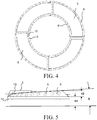
- FIGS. 1 to 5 show an embodiment of a burner cap for gas stoves, which comprises a substantially annular cap body 1, on the underside of a concave gas receiving space 2 is formed.
- a burner cap for gas stoves which comprises a substantially annular cap body 1, on the underside of a concave gas receiving space 2 is formed.
- the four projections 3 which are hollow, wherein the cavity is directly in communication with the gas receiving space 2.
- the four projections 3 continuously increase along the circumference of the cap body 1 in the same direction, ie the Anformung 3 has a thickness or height which increases uniformly, or the top surface 6 of the Anformung 3 extends substantially at a predetermined angle obliquely up.
- a front end face 7 is formed, which is enclosed by an inner side surface 4 of the Anformung, an outer side surface 5 of the Anformung and the upper side surface 6 of the Anformung 3.
- the front end face 7 is radially aligned, i. the front end surface 7 and the upper side of the cap body 1 intersect in a straight line passing through the center of a circle described by the outer edge of the top of the cap body 1. It should be noted that due to the annular configuration of the cap body 1, each of the outer and inner edges of the top of the cap body 1 described circles are arranged concentrically to each other.
- the Anformung 3 is provided on its inner side surface 4 with inner combustion or gas outlets 8 for generating internal flames and on its outer side surface 5 with outer burners or Gasausströmö réelleen 9 for generating external flames.
- located on the outside of the side wall of the cap body 1 according to at least one circumferential Flammenübertragungsnut 12 Fig. 2 and Fig. 5 while on the inside of the side wall of the cap body 1 at least one ring of gas pipe holes 13 according to Fig. 3 is formed, wherein the circumferential Flammenübertragungsnut 12 is connected via the gas line holes 13 with the gas receiving space 2.
- the gas receiving space 2 is in Connection with a gas mixing chamber of the burner holder and serves to receive and forward the fuel gas in the circumferential Flammenübertragungsnut 12 and in the cavity of Anformung 3, wherein the fuel gas respectively from the inner combustion 8, outer burners 9, central burners 10 and from the circulating Flammenübertragungsnut 12th exit to be inflamed.
- the four formations 3 are formed with respect to their structure, the shape and size the same and are distributed uniformly along the circumferential direction of the cap body 1. From the aesthetic point of view, the four formations 3 as a whole form a spiral-shaped structure.
- the individual inner firing points 8 are in each case displaced upward in accordance with the increase in the height of the respective molding 3 but are arranged at a constant distance from the upper surface of the molding 3. The same applies to the outer burners 9.
- the inner combustion stations 8 are arranged at an equal distance from the upper side surface of the respective Anformung 3 as the outer burners 9 to the top surface of the respective Anformung 3. It follows that the inner burners 8 and the outer Burning 9 at the four projections 3 also form a total of a spiral-shaped structure.
- the adjacent inner firing points 8 of an Anformung 3 the same distance from each other. This is also the case with the outer combustion point 9. This ensures a uniform flame distribution.
- the individual inner and outer burners 8, 9 are shifted upward in accordance with the increase in the height of the respective Anformung 3, so that neither the adjacent inner burners 8 nor the adjacent outer burners 9 Anformung 3 in a plane lie. It is understood that in a distance measurement of the straight line distance between the centers of each two adjacent burners to be determined.
- the cap body 1 and the projections 3 are integrally formed, ie they are, for example, fused together at their joint.
- the front end surface 7, the outer side surface 5 and the inner side surface 4 of the Anformung 3 are inclined towards the inside of the Anformung 3, whereby on the one hand a larger area and thus a higher number of burners and a better firing efficiency can be achieved, and saved on the other material becomes.
- the outer side surface 5 of the Anformung 3 with an horizontal plane preferably closes an angle ⁇ with 45 ° ⁇ ⁇ ⁇ 90 °, where ⁇ is particularly preferably 70 °.
- the inner side surface 4 of the Anformung 3 with the horizontal plane an angle ⁇ preferably at 30 ° ⁇ ⁇ ⁇ 60 °, wherein ⁇ is particularly preferably 45 °.
- the front end face 7 of the Anformung 3 with the horizontal plane an angle ⁇ preferably with 30 ° ⁇ ⁇ ⁇ 80 °, particularly preferably with 55 ° ⁇ ⁇ ⁇ 60 °.
- the outer side surface 5 of the Anformung 3 borders with its underside on the outer edge of the top of the cap body 1 and the inner side surface 4 of the Anformung 3 with its underside to the inner edge of the top of the cap body 1.
- a rear end face is formed, which is enclosed by the inner side surface 4, the outer side surface 5 and the upper side surface 6 of the Anformung 3 and lower at its upper side than the lower edge of the central burners 10 on the front end face 7 of an adjacent Anformung 3 is arranged. In this way, a trouble-free outflow of the fuel gas from the central burners 10 can be ensured.
- Adjacent moldings 3 are arranged head to toe, i.
- the inner end 8 is perpendicular to the inner side surface of the Anformung 3, the outer focal point 9 perpendicular to the outer side surface of the Anformung 3 and the central combustion 10th aligned perpendicular to the front end face 7.
- the cap body 1 has a height h1 of 5 mm to 20 mm, preferably 10 mm, and the Anformung 3 a height h2 of 2 mm to 10 mm, preferably 5 mm. Experiments have shown that the height described can lead to optimal combustion performance of the burner cap.
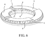
- Fig. 6 shows a further embodiment of a burner cap for gas stoves, which differs from the previously illustrated embodiment in that instead of the central burners 10 in the front end face 7, a groove or recess 11 is formed, which is connected to the cavity of the Anformung 3.
- the recess 11 is used to create a central flame in the combustion process, which should connect the inner flames with the outer flames.
- the recess 11 can additionally serve as a flame transmission groove.
- a rear end face is formed, which is enclosed by the inner side surface 4, the outer side surface 5 and the upper side surface 6 of the Anformung 3 and lower at its top than the lower edge of the recess 11 on the front end face 7 of an adjacent Anformung 3 is arranged. In this way, a trouble-free outflow of the fuel gas from the recess 11 can be sure.
- the present invention further includes an embodiment of a burner for gas stoves, comprising a burner socket with a gas mixing chamber, a burner cap adapted to the burner socket according to one of the embodiments presented above, and a smaller central burner cap.
- the burner cap and the burner holder are matched to each other so that the gas receiving space 2 of the burner cap is in communication with the gas mixing chamber of the burner holder to receive fuel gas from the gas mixing chamber.
- the present invention comprises a gas stove which has a base, pipelines, valves, a cover plate, pot carrier, control electronics and at least one burner with a burner cap according to one of the exemplary embodiments presented above.
Landscapes
- Engineering & Computer Science (AREA)
- Chemical & Material Sciences (AREA)
- Combustion & Propulsion (AREA)
- Mechanical Engineering (AREA)
- General Engineering & Computer Science (AREA)
- Gas Burners (AREA)
- Cookers (AREA)
Claims (15)
- Chapeau de brûleur pour cuisinière à gaz, comprenant un corps formant chapeau (1) annulaire, dont le côté inférieur comporte un espace pour le gaz (2) et dont le côté supérieur présente au moins deux profilés creux (3), un espace creux de chaque profilé (3) étant raccordé à l'espace pour le gaz (2), et les profilés (3) s'élevant en continu dans la même direction le long du pourtour du corps formant chapeau (1), à une extrémité plus élevée du profilé (3) une face frontale (7) avant étant réalisée, laquelle est délimitée par une face latérale intérieure (4), par une face latérale extérieure (5) et par une face latérale supérieure (6) du profilé, et des points de combustion internes étant réalisés respectivement sur chaque face latérale intérieure (4) du profilé (3),
caractérisé en ce que des points de combustion (9) extérieurs sont réalisés sur chaque face latérale extérieure (5) du profilé (3). - Chapeau de brûleur selon la revendication 1, caractérisé en ce que les différents profilés (3) sont réalisés identiques et sont répartis uniformément sur le pourtour du corps formant chapeau (1).
- Chapeau de brûleur selon la revendication 1 ou 2, caractérisé en ce que les points de combustion intérieurs (8) et extérieurs (9) sont décalés vers le haut selon l'augmentation de la hauteur de chaque profilé (3) et sont agencés par rapport à la face latérale supérieure (6) du profilé (3) selon un écartement constant, en ce que les points de combustion (8) intérieurs contigus d'un profilé présentent les uns par rapport aux autres un écartement identique et en ce que les points de combustion (8) extérieurs contigus d'un profilé présentent les uns par rapport aux autres un écartement identique.
- Chapeau de brûleur selon l'une des revendications 1-3, caractérisé en ce que sur la face frontale avant (7) se trouvent des points de combustion (10) centraux.
- Chapeau de brûleur selon l'une des revendications 1-3, caractérisé en ce que sur la face frontale avant (7) se trouve un évidement (11) raccordé à l'espace vide de chaque profilé (3) et qui relie la face latérale intérieure (4) à la face latérale extérieure (5).
- Chapeau de brûleur selon l'une des revendications 1-5, caractérisé en ce que le corps formant chapeau (1) et le profilé (3) sont réalisés en un bloc de même matière.
- Chapeau de brûleur selon l'une des revendications 1-6, caractérisé en ce que la face frontale avant (7) est réalisée radiale.
- Chapeau de brûleur selon l'une des revendications 1-7, caractérisé en ce que la face frontale avant (7), la face latérale extérieure (5) et/ou la face latérale intérieure (4) du profilé (3) sont posées obliquement par rapport au côté intérieur du profilé (3).
- Chapeau de brûleur selon l'une des revendications 1-8, caractérisé en ce que les faces latérales extérieures (5) et intérieures (4) du profilé (3) deviennent, avec leur côté inférieur chacun le bord extérieur ou, selon le cas, intérieur du côté supérieur du corps formant chapeau (1).
- Chapeau de brûleur selon l'une des revendications 1-9, caractérisé en ce que l'extrémité située plus bas du profilé (3) devient le côté supérieur du chapeau de brûleur (1) en un plan.
- Chapeau de brûleur selon l'une des revendications 1-9, caractérisé en ce qu'une face frontale arrière est réalisée sur l'extrémité située plus bas du profilé (3), laquelle est délimitée par la face latérale intérieure (4), par la face latérale extérieure (5) et par la face latérale supérieure (6) du profilé (3), et est disposée sur son côté supérieur plus bas que le bord inférieur des points de combustion (10) centraux ou de l'évidement (11) sur la face frontale avant (7) d'un profilé (3) contigu.
- Chapeau de brûleur selon l'une des revendications 1-9 ou 11, caractérisé en ce que les profilés (3) contigus sont agencés en tête-bêche, en ce qu'une face frontale arrière d'un profilé (3) avant jouxte le côté inférieur sur la face frontale avant (7) d'un profilé (3) arrière contigu.
- Chapeau de brûleur selon l'une des revendications 1-11, caractérisé en ce que les profilés (3) contigus sont écartés l'un de l'autre et qu'un canal d'amenée d'air est créé dans le côté supérieur du corps de chapeau (1) entre les profilés (3) contigus.
- Brûleur pour cuisinière à gaz avec un tube de brûleur présentant un espace de mélange de gaz, un chapeau de brûleur annulaire ajusté au tube de brûleur, selon l'une des revendications 1-13 et un autre chapeau de brûleur central.
- Cuisinière à gaz avec un bâti inférieur, des tuyauteries, des vannes, un dessus de recouvrement, un support de casseroles, un équipement électronique de commande et un brûleur selon la revendication 14.
Applications Claiming Priority (1)
| Application Number | Priority Date | Filing Date | Title |
|---|---|---|---|
| CN201010202881.7A CN102287822B (zh) | 2010-06-18 | 2010-06-18 | 燃气灶用火盖、带有该种火盖的燃烧器及燃气灶 |
Publications (3)
| Publication Number | Publication Date |
|---|---|
| EP2397757A2 EP2397757A2 (fr) | 2011-12-21 |
| EP2397757A3 EP2397757A3 (fr) | 2017-11-15 |
| EP2397757B1 true EP2397757B1 (fr) | 2019-09-11 |
Family
ID=44645328
Family Applications (1)
| Application Number | Title | Priority Date | Filing Date |
|---|---|---|---|
| EP11168944.4A Active EP2397757B1 (fr) | 2010-06-18 | 2011-06-07 | Chapeau de brûleur pour cuisinière à gaz et brûleur doté d'un tel chapeau |
Country Status (2)
| Country | Link |
|---|---|
| EP (1) | EP2397757B1 (fr) |
| CN (1) | CN102287822B (fr) |
Families Citing this family (9)
| Publication number | Priority date | Publication date | Assignee | Title |
|---|---|---|---|---|
| CN103900086B (zh) * | 2014-03-26 | 2015-12-30 | 宁波安佳卫厨电器有限公司 | 一种隐藏式传火槽高效燃烧器 |
| CN104456558B (zh) * | 2014-11-28 | 2017-03-15 | 珠海格力电器股份有限公司 | 燃烧器及具有其的燃气灶 |
| CN104748117A (zh) * | 2015-02-12 | 2015-07-01 | 上海林内有限公司 | 花瓣式大火盖及安装有花瓣式大火盖的燃烧器 |
| CN106895405B (zh) * | 2015-12-18 | 2020-07-14 | 博西华电器(江苏)有限公司 | 燃气燃烧器的火盖、燃气燃烧器及燃气灶 |
| CN106152132B (zh) * | 2016-08-03 | 2018-10-02 | 宁波方太厨具有限公司 | 灶具燃烧器 |
| CN110388645B (zh) * | 2018-04-16 | 2024-08-16 | 宁波方太厨具有限公司 | 一种燃气燃烧器用火盖 |
| CN110887074B (zh) * | 2018-09-09 | 2025-02-07 | 宁波方太厨具有限公司 | 一种灶用聚能罩及应用有该灶用聚能罩的燃气灶 |
| CN109556154B (zh) * | 2018-12-18 | 2023-12-29 | 成都前锋电子有限责任公司 | 一种方便清洗、易调节且燃烧效率高的灶具 |
| CN114440265A (zh) * | 2022-02-25 | 2022-05-06 | 佛山市顺德区美的洗涤电器制造有限公司 | 分气盘、燃烧器以及燃气灶 |
Family Cites Families (8)
| Publication number | Priority date | Publication date | Assignee | Title |
|---|---|---|---|---|
| US5842849A (en) * | 1997-09-05 | 1998-12-01 | Huang; Hsu-Sheng | Gas burner |
| ITVE20050004A1 (it) * | 2005-01-20 | 2006-07-21 | Ohg Defendi S R L | Bruciatore a gas per apparecchiature di cottura. |
| JP3812585B2 (ja) * | 2005-03-18 | 2006-08-23 | 松下電器産業株式会社 | こんろバーナ |
| CN2859238Y (zh) * | 2005-10-28 | 2007-01-17 | 廖珈 | 一种燃气灶火盖 |
| US7871264B2 (en) * | 2006-12-29 | 2011-01-18 | Electrolux Home Products, Inc. | Hub and spoke burner port configuration |
| CN201129728Y (zh) * | 2007-09-25 | 2008-10-08 | 明协华 | 分火器 |
| CN201209862Y (zh) | 2008-01-23 | 2009-03-18 | 周建基 | 一种设有保洁传焰带的火盖 |
| CN101737782B (zh) * | 2008-11-21 | 2012-08-29 | 博西华电器(江苏)有限公司 | 燃气灶炉头火盖及带有该种火盖的炉头 |
-
2010
- 2010-06-18 CN CN201010202881.7A patent/CN102287822B/zh not_active Expired - Fee Related
-
2011
- 2011-06-07 EP EP11168944.4A patent/EP2397757B1/fr active Active
Non-Patent Citations (1)
| Title |
|---|
| None * |
Also Published As
| Publication number | Publication date |
|---|---|
| CN102287822A (zh) | 2011-12-21 |
| EP2397757A2 (fr) | 2011-12-21 |
| EP2397757A3 (fr) | 2017-11-15 |
| CN102287822B (zh) | 2015-11-25 |
Similar Documents
| Publication | Publication Date | Title |
|---|---|---|
| EP2397757B1 (fr) | Chapeau de brûleur pour cuisinière à gaz et brûleur doté d'un tel chapeau | |
| EP2290287B1 (fr) | Chapeau de brûleur pour cuisinière à gaz et brûleur doté d'un tel chapeau | |
| DE69315233T2 (de) | Gaskochherdbrenner mit drei konzentrischen Flammen | |
| EP2211095B1 (fr) | Brûleur à gaz | |
| DE69908468T2 (de) | Gasbrenner für Kochgeräte | |
| DE10012578C2 (de) | Kochfeld | |
| EP2090826A1 (fr) | Brûleur à gaz | |
| EP3278024B1 (fr) | Brûleur à gaz avec couvercle de brûleur | |
| EP2556304B1 (fr) | Support pour récipient et cuisinière à gaz | |
| EP3679301B1 (fr) | Grille, table de cuisson à gaz et procédé de fabrication d'une grille | |
| EP2984410B1 (fr) | Système de support de récipient et cuisinière à gaz | |
| DE69830753T2 (de) | Tiefgezogene brennvorichtung | |
| DE60112818T2 (de) | Kochgerät | |
| DE102013218852A1 (de) | Anordnung von Gasbrennern | |
| DE3018794C2 (de) | Gasherd mit einer wärmeübertragenden Platte und einem Strahlungsbrenner | |
| EP2439449B1 (fr) | Brûleur à gaz pour un réchaud | |
| EP3990832B1 (fr) | Support de casserole, plaque de cuisson à gaz et procédé de production d'un support de casserole | |
| DE69206501T2 (de) | Infrarotstrahlungsbrenner für Glaskeramik-Kochmulde. | |
| EP3450852B1 (fr) | Poste de cuisson à gaz et cuisinière à gaz | |
| DE102008019572B4 (de) | Brennerkrone mit Ausgabelöchern auf verschiedenen Ebenen und abwechselnd, einstückig, mit hoher Leistung für Brenner von Großküchen zum Kochen von Lebensmitteln | |
| DE2107215C3 (de) | Grillplatte für Gasofen | |
| WO2017220089A1 (fr) | Grill et/ou appareil de cuisson | |
| DE69501673T2 (de) | Verbesserungen an Gasbrennern | |
| DE102014208409A1 (de) | Heizkörper für ein Gargerät sowie Gargerät mit einem Heizkörper | |
| DE2107215B2 (de) | Grillplatte fuer gasoefen |
Legal Events
| Date | Code | Title | Description |
|---|---|---|---|
| AK | Designated contracting states |
Kind code of ref document: A2 Designated state(s): AL AT BE BG CH CY CZ DE DK EE ES FI FR GB GR HR HU IE IS IT LI LT LU LV MC MK MT NL NO PL PT RO RS SE SI SK SM TR |
|
| AX | Request for extension of the european patent |
Extension state: BA ME |
|
| PUAI | Public reference made under article 153(3) epc to a published international application that has entered the european phase |
Free format text: ORIGINAL CODE: 0009012 |
|
| RIN1 | Information on inventor provided before grant (corrected) |
Inventor name: LIU, SHENCHANG Inventor name: LUO, HAITAO Inventor name: ZHANG, SHENZHOU Inventor name: MIAO, WEIWEI |
|
| RAP1 | Party data changed (applicant data changed or rights of an application transferred) |
Owner name: BSH HAUSGERAETE GMBH |
|
| PUAL | Search report despatched |
Free format text: ORIGINAL CODE: 0009013 |
|
| AK | Designated contracting states |
Kind code of ref document: A3 Designated state(s): AL AT BE BG CH CY CZ DE DK EE ES FI FR GB GR HR HU IE IS IT LI LT LU LV MC MK MT NL NO PL PT RO RS SE SI SK SM TR |
|
| AX | Request for extension of the european patent |
Extension state: BA ME |
|
| RIC1 | Information provided on ipc code assigned before grant |
Ipc: F23D 14/58 20060101ALI20171011BHEP Ipc: F23D 14/06 20060101AFI20171011BHEP |
|
| STAA | Information on the status of an ep patent application or granted ep patent |
Free format text: STATUS: REQUEST FOR EXAMINATION WAS MADE |
|
| 17P | Request for examination filed |
Effective date: 20180515 |
|
| RBV | Designated contracting states (corrected) |
Designated state(s): AL AT BE BG CH CY CZ DE DK EE ES FI FR GB GR HR HU IE IS IT LI LT LU LV MC MK MT NL NO PL PT RO RS SE SI SK SM TR |
|
| GRAP | Despatch of communication of intention to grant a patent |
Free format text: ORIGINAL CODE: EPIDOSNIGR1 |
|
| STAA | Information on the status of an ep patent application or granted ep patent |
Free format text: STATUS: GRANT OF PATENT IS INTENDED |
|
| INTG | Intention to grant announced |
Effective date: 20190417 |
|
| GRAS | Grant fee paid |
Free format text: ORIGINAL CODE: EPIDOSNIGR3 |
|
| GRAA | (expected) grant |
Free format text: ORIGINAL CODE: 0009210 |
|
| STAA | Information on the status of an ep patent application or granted ep patent |
Free format text: STATUS: THE PATENT HAS BEEN GRANTED |
|
| AK | Designated contracting states |
Kind code of ref document: B1 Designated state(s): AL AT BE BG CH CY CZ DE DK EE ES FI FR GB GR HR HU IE IS IT LI LT LU LV MC MK MT NL NO PL PT RO RS SE SI SK SM TR |
|
| REG | Reference to a national code |
Ref country code: GB Ref legal event code: FG4D Free format text: NOT ENGLISH |
|
| REG | Reference to a national code |
Ref country code: CH Ref legal event code: EP |
|
| REG | Reference to a national code |
Ref country code: AT Ref legal event code: REF Ref document number: 1178901 Country of ref document: AT Kind code of ref document: T Effective date: 20190915 |
|
| REG | Reference to a national code |
Ref country code: DE Ref legal event code: R096 Ref document number: 502011016087 Country of ref document: DE Ref country code: IE Ref legal event code: FG4D Free format text: LANGUAGE OF EP DOCUMENT: GERMAN |
|
| REG | Reference to a national code |
Ref country code: NL Ref legal event code: MP Effective date: 20190911 |
|
| REG | Reference to a national code |
Ref country code: LT Ref legal event code: MG4D |
|
| PG25 | Lapsed in a contracting state [announced via postgrant information from national office to epo] |
Ref country code: FI Free format text: LAPSE BECAUSE OF FAILURE TO SUBMIT A TRANSLATION OF THE DESCRIPTION OR TO PAY THE FEE WITHIN THE PRESCRIBED TIME-LIMIT Effective date: 20190911 Ref country code: HR Free format text: LAPSE BECAUSE OF FAILURE TO SUBMIT A TRANSLATION OF THE DESCRIPTION OR TO PAY THE FEE WITHIN THE PRESCRIBED TIME-LIMIT Effective date: 20190911 Ref country code: SE Free format text: LAPSE BECAUSE OF FAILURE TO SUBMIT A TRANSLATION OF THE DESCRIPTION OR TO PAY THE FEE WITHIN THE PRESCRIBED TIME-LIMIT Effective date: 20190911 Ref country code: BG Free format text: LAPSE BECAUSE OF FAILURE TO SUBMIT A TRANSLATION OF THE DESCRIPTION OR TO PAY THE FEE WITHIN THE PRESCRIBED TIME-LIMIT Effective date: 20191211 Ref country code: LT Free format text: LAPSE BECAUSE OF FAILURE TO SUBMIT A TRANSLATION OF THE DESCRIPTION OR TO PAY THE FEE WITHIN THE PRESCRIBED TIME-LIMIT Effective date: 20190911 Ref country code: NO Free format text: LAPSE BECAUSE OF FAILURE TO SUBMIT A TRANSLATION OF THE DESCRIPTION OR TO PAY THE FEE WITHIN THE PRESCRIBED TIME-LIMIT Effective date: 20191211 |
|
| PG25 | Lapsed in a contracting state [announced via postgrant information from national office to epo] |
Ref country code: ES Free format text: LAPSE BECAUSE OF FAILURE TO SUBMIT A TRANSLATION OF THE DESCRIPTION OR TO PAY THE FEE WITHIN THE PRESCRIBED TIME-LIMIT Effective date: 20190911 Ref country code: LV Free format text: LAPSE BECAUSE OF FAILURE TO SUBMIT A TRANSLATION OF THE DESCRIPTION OR TO PAY THE FEE WITHIN THE PRESCRIBED TIME-LIMIT Effective date: 20190911 Ref country code: AL Free format text: LAPSE BECAUSE OF FAILURE TO SUBMIT A TRANSLATION OF THE DESCRIPTION OR TO PAY THE FEE WITHIN THE PRESCRIBED TIME-LIMIT Effective date: 20190911 Ref country code: RS Free format text: LAPSE BECAUSE OF FAILURE TO SUBMIT A TRANSLATION OF THE DESCRIPTION OR TO PAY THE FEE WITHIN THE PRESCRIBED TIME-LIMIT Effective date: 20190911 Ref country code: GR Free format text: LAPSE BECAUSE OF FAILURE TO SUBMIT A TRANSLATION OF THE DESCRIPTION OR TO PAY THE FEE WITHIN THE PRESCRIBED TIME-LIMIT Effective date: 20191212 |
|
| PG25 | Lapsed in a contracting state [announced via postgrant information from national office to epo] |
Ref country code: PL Free format text: LAPSE BECAUSE OF FAILURE TO SUBMIT A TRANSLATION OF THE DESCRIPTION OR TO PAY THE FEE WITHIN THE PRESCRIBED TIME-LIMIT Effective date: 20190911 Ref country code: EE Free format text: LAPSE BECAUSE OF FAILURE TO SUBMIT A TRANSLATION OF THE DESCRIPTION OR TO PAY THE FEE WITHIN THE PRESCRIBED TIME-LIMIT Effective date: 20190911 Ref country code: PT Free format text: LAPSE BECAUSE OF FAILURE TO SUBMIT A TRANSLATION OF THE DESCRIPTION OR TO PAY THE FEE WITHIN THE PRESCRIBED TIME-LIMIT Effective date: 20200113 Ref country code: RO Free format text: LAPSE BECAUSE OF FAILURE TO SUBMIT A TRANSLATION OF THE DESCRIPTION OR TO PAY THE FEE WITHIN THE PRESCRIBED TIME-LIMIT Effective date: 20190911 Ref country code: NL Free format text: LAPSE BECAUSE OF FAILURE TO SUBMIT A TRANSLATION OF THE DESCRIPTION OR TO PAY THE FEE WITHIN THE PRESCRIBED TIME-LIMIT Effective date: 20190911 |
|
| PG25 | Lapsed in a contracting state [announced via postgrant information from national office to epo] |
Ref country code: CZ Free format text: LAPSE BECAUSE OF FAILURE TO SUBMIT A TRANSLATION OF THE DESCRIPTION OR TO PAY THE FEE WITHIN THE PRESCRIBED TIME-LIMIT Effective date: 20190911 Ref country code: IS Free format text: LAPSE BECAUSE OF FAILURE TO SUBMIT A TRANSLATION OF THE DESCRIPTION OR TO PAY THE FEE WITHIN THE PRESCRIBED TIME-LIMIT Effective date: 20200224 Ref country code: SK Free format text: LAPSE BECAUSE OF FAILURE TO SUBMIT A TRANSLATION OF THE DESCRIPTION OR TO PAY THE FEE WITHIN THE PRESCRIBED TIME-LIMIT Effective date: 20190911 Ref country code: SM Free format text: LAPSE BECAUSE OF FAILURE TO SUBMIT A TRANSLATION OF THE DESCRIPTION OR TO PAY THE FEE WITHIN THE PRESCRIBED TIME-LIMIT Effective date: 20190911 |
|
| REG | Reference to a national code |
Ref country code: DE Ref legal event code: R097 Ref document number: 502011016087 Country of ref document: DE |
|
| PLBE | No opposition filed within time limit |
Free format text: ORIGINAL CODE: 0009261 |
|
| STAA | Information on the status of an ep patent application or granted ep patent |
Free format text: STATUS: NO OPPOSITION FILED WITHIN TIME LIMIT |
|
| PG2D | Information on lapse in contracting state deleted |
Ref country code: IS |
|
| PG25 | Lapsed in a contracting state [announced via postgrant information from national office to epo] |
Ref country code: DK Free format text: LAPSE BECAUSE OF FAILURE TO SUBMIT A TRANSLATION OF THE DESCRIPTION OR TO PAY THE FEE WITHIN THE PRESCRIBED TIME-LIMIT Effective date: 20190911 Ref country code: IS Free format text: LAPSE BECAUSE OF FAILURE TO SUBMIT A TRANSLATION OF THE DESCRIPTION OR TO PAY THE FEE WITHIN THE PRESCRIBED TIME-LIMIT Effective date: 20200112 |
|
| 26N | No opposition filed |
Effective date: 20200615 |
|
| PG25 | Lapsed in a contracting state [announced via postgrant information from national office to epo] |
Ref country code: SI Free format text: LAPSE BECAUSE OF FAILURE TO SUBMIT A TRANSLATION OF THE DESCRIPTION OR TO PAY THE FEE WITHIN THE PRESCRIBED TIME-LIMIT Effective date: 20190911 |
|
| PGFP | Annual fee paid to national office [announced via postgrant information from national office to epo] |
Ref country code: IT Payment date: 20200630 Year of fee payment: 10 |
|
| REG | Reference to a national code |
Ref country code: DE Ref legal event code: R119 Ref document number: 502011016087 Country of ref document: DE |
|
| PG25 | Lapsed in a contracting state [announced via postgrant information from national office to epo] |
Ref country code: MC Free format text: LAPSE BECAUSE OF FAILURE TO SUBMIT A TRANSLATION OF THE DESCRIPTION OR TO PAY THE FEE WITHIN THE PRESCRIBED TIME-LIMIT Effective date: 20190911 |
|
| REG | Reference to a national code |
Ref country code: CH Ref legal event code: PL |
|
| GBPC | Gb: european patent ceased through non-payment of renewal fee |
Effective date: 20200607 |
|
| PG25 | Lapsed in a contracting state [announced via postgrant information from national office to epo] |
Ref country code: LU Free format text: LAPSE BECAUSE OF NON-PAYMENT OF DUE FEES Effective date: 20200607 |
|
| REG | Reference to a national code |
Ref country code: BE Ref legal event code: MM Effective date: 20200630 |
|
| PG25 | Lapsed in a contracting state [announced via postgrant information from national office to epo] |
Ref country code: CH Free format text: LAPSE BECAUSE OF NON-PAYMENT OF DUE FEES Effective date: 20200630 Ref country code: IE Free format text: LAPSE BECAUSE OF NON-PAYMENT OF DUE FEES Effective date: 20200607 Ref country code: LI Free format text: LAPSE BECAUSE OF NON-PAYMENT OF DUE FEES Effective date: 20200630 Ref country code: GB Free format text: LAPSE BECAUSE OF NON-PAYMENT OF DUE FEES Effective date: 20200607 Ref country code: FR Free format text: LAPSE BECAUSE OF NON-PAYMENT OF DUE FEES Effective date: 20200630 |
|
| PG25 | Lapsed in a contracting state [announced via postgrant information from national office to epo] |
Ref country code: BE Free format text: LAPSE BECAUSE OF NON-PAYMENT OF DUE FEES Effective date: 20200630 Ref country code: DE Free format text: LAPSE BECAUSE OF NON-PAYMENT OF DUE FEES Effective date: 20210101 |
|
| REG | Reference to a national code |
Ref country code: AT Ref legal event code: MM01 Ref document number: 1178901 Country of ref document: AT Kind code of ref document: T Effective date: 20200607 |
|
| PG25 | Lapsed in a contracting state [announced via postgrant information from national office to epo] |
Ref country code: AT Free format text: LAPSE BECAUSE OF NON-PAYMENT OF DUE FEES Effective date: 20200607 |
|
| PG25 | Lapsed in a contracting state [announced via postgrant information from national office to epo] |
Ref country code: MT Free format text: LAPSE BECAUSE OF FAILURE TO SUBMIT A TRANSLATION OF THE DESCRIPTION OR TO PAY THE FEE WITHIN THE PRESCRIBED TIME-LIMIT Effective date: 20190911 Ref country code: CY Free format text: LAPSE BECAUSE OF FAILURE TO SUBMIT A TRANSLATION OF THE DESCRIPTION OR TO PAY THE FEE WITHIN THE PRESCRIBED TIME-LIMIT Effective date: 20190911 |
|
| PG25 | Lapsed in a contracting state [announced via postgrant information from national office to epo] |
Ref country code: MK Free format text: LAPSE BECAUSE OF FAILURE TO SUBMIT A TRANSLATION OF THE DESCRIPTION OR TO PAY THE FEE WITHIN THE PRESCRIBED TIME-LIMIT Effective date: 20190911 |
|
| PG25 | Lapsed in a contracting state [announced via postgrant information from national office to epo] |
Ref country code: IT Free format text: LAPSE BECAUSE OF NON-PAYMENT OF DUE FEES Effective date: 20210607 |
|
| PGFP | Annual fee paid to national office [announced via postgrant information from national office to epo] |
Ref country code: TR Payment date: 20230601 Year of fee payment: 13 |