EP0283998A2 - Système pour maintenir, porter et répertorier des cartes et casier de transport adapté - Google Patents
Système pour maintenir, porter et répertorier des cartes et casier de transport adapté Download PDFInfo
- Publication number
- EP0283998A2 EP0283998A2 EP88104490A EP88104490A EP0283998A2 EP 0283998 A2 EP0283998 A2 EP 0283998A2 EP 88104490 A EP88104490 A EP 88104490A EP 88104490 A EP88104490 A EP 88104490A EP 0283998 A2 EP0283998 A2 EP 0283998A2
- Authority
- EP
- European Patent Office
- Prior art keywords
- card
- holding means
- card holding
- retaining
- carrying
- Prior art date
- Legal status (The legal status is an assumption and is not a legal conclusion. Google has not performed a legal analysis and makes no representation as to the accuracy of the status listed.)
- Withdrawn
Links
Images


Classifications
-
- B—PERFORMING OPERATIONS; TRANSPORTING
- B42—BOOKBINDING; ALBUMS; FILES; SPECIAL PRINTED MATTER
- B42F—SHEETS TEMPORARILY ATTACHED TOGETHER; FILING APPLIANCES; FILE CARDS; INDEXING
- B42F19/00—File cards
-
- B—PERFORMING OPERATIONS; TRANSPORTING
- B42—BOOKBINDING; ALBUMS; FILES; SPECIAL PRINTED MATTER
- B42F—SHEETS TEMPORARILY ATTACHED TOGETHER; FILING APPLIANCES; FILE CARDS; INDEXING
- B42F17/00—Card-filing arrangements, e.g. card indexes or catalogues or filing cabinets
- B42F17/02—Card-filing arrangements, e.g. card indexes or catalogues or filing cabinets in which the cards are stored substantially at right angles to the bottom of their containers
- B42F17/08—Construction of the containers, e.g. trays or drawers
Definitions
- the present invention relates to an improved apparatus for holding, carrying and retaining cards, particularly business cards.
- card filing systems are well known in the prior art.
- a multiplicity of filing cards are placed in a filing card retaining means.
- Conventional filing card retaining means include a tray or a wheel in which the filing cards are placed, such as those manufactured by Eldon or by Rolodex respectively.
- the tray card holder or rotary card holder includes one or more card holding means such as tracks, rails, cylindrical rods, etc. onto which the filing cards are movably inserted.
- the filing cards in turn, having mating slots adjacent their lower edge by which the cards may be movably and removably inserted onto the tracks, rails, rods, etc. of the card holding means.
- the business card may be somehow attached to the filing card such as by tape or staples. Since the business card is usually about the same height as the filing card and an allowance must be made for the slots by which the filing card is movably attached to the tracks in the card holder, the business card is often too tall for the card holder trays, thereby preventing the tray from being closed. It is therefore necessary to cut the business card so that it fits onto the filing card so that the tray can be closed while at the same time not interfering with the slots at the lower edge of the filing card. Since telephone numbers and/or addresses are frequently placed adjacent the top or bottom of the card, this information is cut off and therefore must be written onto the body of the card.
- Rolodex type trays have a closing lid to prevent the cards from getting dirty. Others, are left exposed.
- the tray itself does not include an appropriately fitted housing member so that the cards may be stored and thereby reduce the likelihood that they will become soiled.
- the present invention relates to an improved system whereby a business card can be immediately placed onto a card holding means which permits the card to be immediately stored in a card carrying means which can be carried in a coat pocket or purse and further upon return to one's office permits the business card to be immediately removed from the card carrying means and placed in a desk card retaining means such as a card file or rotary file without any need for physical alteration of the business card or transcription of the information from the business card to the filing card.
- the present invention relates to a housing member which perfectly matches the desk card retaining means to keep the cards and desk card retaining means or tray covered when not in use to thereby assure that the cards and tray will not become dirty by means such as food or drink being spilled on them.
- the matching housing member further includes features such as a tray to retain cards before they are alphabetically filed in the desk card retaining means.
- the present invention relates to a matching case member which permits a multiplicity of card carrying means to be stored and carried in a preselected order.
- the user can remove the business cards and associated card holding means from the card retaining means and place them in the card carrying means.
- the matching case member can hold a multiplicity of card carrying members in a preselected order with the associated preselected business cards therein. In this way, a business trip can be efficiently organized with the cards for individuals or business to be called on in a given morning placed in one card carrying means and the cards for individuals or businesses to be called on in the afternoon and during future days to be placed in selected additional card carrying means.
- the present invention further permits the business card to be removed from the card retaining means and placed in the card carrying means for use when the individual is going to a meeting with that person, thereby eliminating the necessity of once again transcribing the information from the card in the card retaining means onto a piece of paper to be taken by the individual to the meeting.
- a card holding means such as a strip member.
- the card holding means comprises at least one retaining means 12 located on one edge 14 of the card holding means.
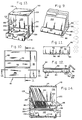
- the strip retaining means are two slots 12, as shown in Figure 1, with each slot having a wide portion 16 located in the body 20 of the card holding means or strip member 10, and a narrow portion 18 opening into the edge 14 of strip member 10 such that the card holding means may be inserted onto a pair of tracks or rails through its narrow portion 18 and retained by its wider portion 16.
- the card holding means or strip member 10 further comprises a self adhesive section 24.
- the self adhesive section 24 is a strip located adjacent an edge 26 directly opposite to the edge along which the strip retaining means 12 are located, and further located on one face 30 of the card holding means 10.
- the self adhesive section 24 is protected by a removable section covering means 32 which completely covers the self adhesive section 24 when the card holding means 10 is not in use, as illustrated in Figure 1 and is peeled off (as partially shown in Figure 2) when the card holding means is to be used.
- the removable section covering means 32 is a paper strip which is removably placed over the self adhesive section.
- a card such as a business card 40 can be permanently attached to the card holding means 10 by aligning the card 40 onto the card holding means 10 and pressing the back of the card onto and against the uncovered self adhesive section 24 until a firm bond is secured.
- the bottom of the card 40 has been aligned just above the upper portion of the strip retaining means 12. It will be appreciated that the business card 40 could be aligned at any location although the embodiment shown in Figure 3 is preferred since it provides the shortest practical combined vertical height of the business card 40 and card holding means 10. Therefore, a card 40 can be easily and permanently retained on the card holding means 10.
- the card holding means is a rectangular strip which is approximately the same length as a conventional business card.
- Conventional business cards are approximately 9 cm (3.5 inches) long and 5.5 cm (2 inches) high.
- the strip is approximately 9 cm (3.5 inches) long and 2.75 cm (1.125 inches) high.
- the two slots extend through the faces of the strip and extend out one edge. They are spaced apart such that the distance 15 between their centers is approximately 2.54 cm (1 inch). This conforms to the distance between the longitudinal centerlines of the tracks on card retaining files such as those made by Eldon or Rolodex.
- the self adhesive section is a strip located on one face of the rectangular strip.
- one convenient method of storing a multiplicity of unused card holding means 10 is to detachably affix two such card holding means 10 to each other along one lengthwise edge by a perforated central strip 11.
- the card holding means 10 are to be used, they are torn apart at the location of the perforated central strip 11.
- the card carrying means or case 50 comprises at least one rail or track 52 which can accommodate the strip retaining means 12 of the card holding means 10.
- a pair of rods or tracks are aligned in generally parallel relationship to each other and spaced apart so that their longitudinal centerlines are approximately the same distance apart as the distance between the centers of the strip retaining means 12 on the card holding members 10.
- the configuration of the remainder of the card carrying means or case 50 is optional and one of many possible embodiments is illustrated in Figure 5.
- the card carrying case 50 comprises a front ledge 54, a bottom 56, a rear portion 58 and a flexible cover 60 which can be opened to permit insertion of the card holding means 10 (with or without business cards attached) and thereafter closed by folding the lower edge 61 of the cover 60 immediately behind the front ledge 54, thereby protecting the card holding means 10 and attached cards 40 inside the card carrying case 50.
- the rods or tracks are held in place by being affixed to the front ledge and rear portion of the card carrying case. As shown in Figure 5, the card holding means 10 can be snapped into place on the rods or tracks 52 through the narrow portion 18 and held therein by the wider portion 16 of the strip retaining means 12.
- the card holding means 10 can be snapped into place on the rods or tracks 52 of the card carrying case 50 and retained thereon for ready use. At such time as a card holding means 10 is needed, it can be easily snapped out of its position in the card carrying case 50 and the card 40 can be permanently affixed to the card holding means 10 as previously described. As shown in Figure 5, the internal height of the card carrying means 50 is large enough to accommodate a conventional business card affixed to the card holding member 10. Through this method, a card 40 can be immediately affixed to a card holding member 10 and thereafter movably and removably held in the card carrying case 50.
- the business cards can be removed from the card carrying case 50 and snapped into place in the card retaining file.
- the card retaining means 60 must comprise at least one rail or track which can accommodate the strip retaining means or slots 12 of the card holding member 10.
- the card retaining means 60 is a file which has a pair of rods or tracks 62 which are aligned in generally parallel relationship to each other and spaced apart so that their longitudinal centerlines are approximately the same distance apart as the distance between the centers of the strip retaining means 12 on the card holding means 10.
- One additional feature on the card retaining file is a well or temporary card placement area 64 located at the front of the file. Cards can be placed in this area and later filed alphabetically. While the card retaining means 60 is shown in Figures 6 and 7 as an open tray, it will be appreciated that it can be an enclosed type file comparable to the ones commercially sold by Eldon Corporation.
- the rotary card retaining means 70 comprises at least one rail or track 72 which can accommodate the strip retaining means 12 of the card holding member 10.
- the rotary card retaining means 70 is a file which has a pair of tracks 72 which are aligned in generally equidistant relationship to each other along a circular path and spaced apart so that their longitudinal centerlines are approximately the same distance apart as the distance between the centers of the strip retaining means 12 on the card holding means 10.
- FIG. 9 is a perspective view of an open card retaining means 80 such as a card file tray. Also shown in Figure 9 is a multiplicity of separator members 100 used to divide the cards along a specific order, such as alphabetical order.
- Figure 10 is a top plan view of the card retaining means 80.
- Figure 11 is a cross-sectional view taken along line 11-11 of Figure 10.
- Figure 12 is a cross-sectional view taken along line 12-12 of Figure 10.
- the body of the card retaining means 80 is formed of one piece construction (as by plastic injection molding) and comprises a rear wall 82, a floor 84, a front wall 86 and a handle 88.
- the front wall 86 and the rear wall 82 are generally parallel to each other and are generally perpendicular to the floor 84.
- the handle 88 extends from the front wall 86 and is preferably offset at an angle thereto.
- a well 90 is formed by and bounded by the front wall 86, the floor 84 and the rear wall 82.
- the card retaining means must comprise at least one rail or track which can accommodate the strip retaining means or slots 12 of the card holding member 10.
- the card retaining means 80 comprises a pair of rods or tracks 92 and 94 respectively which are aligned in generally parallel relationship to each other and spaced apart so that their longitudinal centerlines are approximately the same distance apart as the distance between the centers of the strip retaining means 12 on the card holding means 10.
- the pair of rods 92 and 94 are aligned in the well 90 and as illustrated in Figure 12 extend for the entire length of the well 90 from the front wall 86 to the rear wall 82.
- the rods are part of the one piece construction of the front wall, floor and side wall, and extend upwardly from the floor.
- Rod 92 is supported on stem 96 which extends from floor 84 and rod 94 is supported on stem 98 which extends from floor 84.
- the rod 92 is offset from the stem 96 so that one portion of the circumference of each rod is aligned with the inwardmost portion of its supporting stem, as shown in Figure 11.
- the rod it is also possible for the rod to be centered on its supporting stem.
- the rods could be merely cylindrical tubes which are supported by the front and rear walls, comparable to the illustration of the embodiment shown in Figure 7.
- the card holding means 10 and associated cards 40 are supported on the rods 92 and 94 as previously described.
- the card retaining means 80 can itself be retained within a housing member whose interior dimensions are design to accommodate the card retaining means 80 when it is filled with card holding means 10 and associated cards 40.
- a preferred embodiment of such a housing member 110 is illustrated in Figure 13.
- the housing member 110 is comprised of an open faced chamber which includes and is bounded by a pair of generally parallel and oppositely disposed side walls 112 and 114 and a pair of generally parallel and oppositely disposed walls 116 and 118 which serve as the top and bottom walls respectively.
- a rear wall 120 completes the chamber which is completely open on its front surface area 122.
- all of the walls 112, 114, 116, 118 and 120 are created in a one-piece construction (such as by plastic injection molding) and essentially form a box which is open on one face.
- the embodiment shown in Figure 13 is generally square, but other shapes such as rectangular with walls 112, 114, 116, and 118 being longer than wall 120 are within the spirit and scope of the present invention.
- the interior surface of side walls 112 and 114 further comprise a pair of rails or shelves.
- Interior surface 113 of side wall 112 comprises a pair of rails or shelves 124 and 126. As illustrated in Figure 14, each rail or shelf 124 and 126 abuts rear wall 120 and extends forward to a distance adjacent but not at the front opening 122.
- the interior surface of side wall 114 also comprises a pair of rails or shelves 128 and 130 which are oppositely disposed to the rails or shelves 124 and 126, and are parallel to them, to thereby form two sets of rails.
- Lower rails 124 and 128 are oppositely disposed and parallel to each other.
- Upper rails 126 and 130 are oppositely disposed and parallel to each other.
- Rails 124 and 126 are generally parallel to each other and as illustrated in Figure 14 are set apart by a distance slightly larger than the height of rear wall 82 of card retaining member 80.
- Rails 128 and 130 are generally parallel to each other and are set apart by a distance slightly larger than the height of rear wall 82 of card retaining member 80.
- the distance between lower rails 124 and 128 and the floor 118 is set so that the card retaining means 80 filled with card holding means 10 and associated cards 40 and separator members 100 can fit within the interior space 130 of housing means 110.
- the card retaining means 80 is inserted into the housing means 110 such that the respective edges of the floor 84 slidably rest on a respective one of the lower rails protruding from the interior sidewalls of the housing means 110 and such that the respective edges of the rear wall 82 abuts a respective one of the lower surfaces of the upper rails protruding form the interior sidewalls of the case member, as illustrated in Figure 14.
- the rails 124, 126, 128 and 130 protrude only a sufficient distance so as to provide support for the floor 84 and stabilization on the rear wall 82, and not so far into the space 132 so as to interfere with the business cards 40 or separator members 100.
- the housing member 110 further comprises a slidable tray 140 whose dimensions are designed to fit within space 134.
- the upper portion of the sidewalls of tray 140 abut the lower portions of lower rails 124 and 128 such that the tray 140 can slide in and out of the housing member or means 110 along its floor 118.
- the tray can be used to hold business cards 40 which have not yet been filed in the card retaining means 80.
- the card retaining means 14 is inserted such that the handle 88 protrudes from the open surface 122. It is also within the spirit and scope of the present invention to make the housing member 110 sufficiently deep to accommodate the handle within the space 132 such that the handle 88 does not protrude from the case member 110.
- a least one opening in the rear wall 120 serves to provide a means for mounting the housing member 110 on a wall or other surface.
- the rear wall 120 of housing member 110 includes a pair of openings or mounting means 121 and 123 by which the housing member can be mounted on a wall or other surface (through hooks, nails or comparable apparatus).
- the housing member 110 may also include a multiplicity of stacking means 127 such as Bumpons ⁇ * located on the lower surface 118, as illustrated in Figure 14.
- stacking means 127 such as Bumpons ⁇ * located on the lower surface 118, as illustrated in Figure 14.
- the Bumpons ⁇ provide a nonslip surface by which the housing members can be stacked one on top of the other.
- Comparable stacking means or Bumpons ⁇ 129 can be located on the lower such of the card retaining means 50 (as illustrated in Figure 14) to enable them to be more easily used on a surface, as the Bumpons ⁇ 129 provide a non-slip surface.
- the present invention includes an entire system which comprises the card holder member, the card carrying means, the card retaining means and the housing member or means.
- the housing member and its associated components can be made of plastic or any other suitable material such as pressed cardboard or styrofoam.
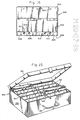
- the case means 150 is illustrated in Figure 15 and includes a conventional case comprising a rectangular shaped base 152 having a floor and four walls and defining an interior space 154 therein.
- the case 150 is closed by a lid 160 which can be hingeably attached to the base 150 at end one.
- the interior space 154 is partitioned into a multiplicity of slots 162, each of which is shaped in the same configuration as a card carrying means and is just large enough to accommodate one card carrying means 50.
- the space 154 is partitioned into two parallel rows of slots as illustrated in Figure 15.
- the slots can be formed of styrofoam, rubber, or other insert material which can be individually formed and then inserted into the case means 150.
- the slots can be made of wood or comparable material and built into the case means 150.
- the case means 50 may include a handle 156.
- the user can remove the business cards and associated card holding means from the card retaining means and place them in the card carrying member.
- the matching case means 150 can hold a multiplicity of card carrying means 50 within each of the respect slots 162 in a preselected order with the associated preselected business cards therein. In this way, a business trip can be efficiently organized with the cards for individuals or business to be called on in a given morning placed in one card carrying means 50 and the cards for individuals or businesses to be called on in the afternoon and during future days to be placed in selected additional card carrying means.
- the card carrying case 50 is to carry the business cards 40 in an alternative embodiment of the present invention which is designed to be used in conjunction with a conventional loose-leaf planner or organizer.
- the planner cards carrying means 200 comprises a back sheet 202 which can be made of plastic, cardboard, or comparable suitable material, and which is generally rectangular in shape and is dimensioned to fit into a conventional loose-leaf planner or organizer.
- the back sheet 202 includes a multiplicity of holes 204 adjacent one longitudinal edge and aligned to fit onto the rings of the loose-leaf planner.
- the preferred embodiment is three holes 204 as illustrated in Figure 16, but any embodiment with two or more holes is within the spirit and scope of the present invention.
- each card carrying section further comprises at least one rail or track which can accommodate the strip retaining means 12 of the card holding means 10.
- each section 205 has a pair of rods or tracks 210 and 212 which are aligned in generally parallel relationship to each other and spaced apart so that their longitudinal centerlines are approximately the same distance apart as the distance between the centers of the strip retaining means 12 on the card holding means 10.
- the rods or tracks 210 and 212 are supported by the front wall 206 and the portion of the back sheet 202 parallel to the front wall 206.
- there are two such sections 205 but it will be appreciated that any multiplicity of sections are within the spirit and scope of the present invention and are limited only by the design of the planner or organizer for which the particular embodiment is designed.
- the two sections 205 are aligned adjacent each other, however they can also be aligned one above the other if the width of the back sheet 202 for the particular embodiment has sufficient room to permit this design.
Landscapes
- Sheet Holders (AREA)
Applications Claiming Priority (4)
| Application Number | Priority Date | Filing Date | Title |
|---|---|---|---|
| US2973587A | 1987-03-24 | 1987-03-24 | |
| US29735 | 1987-03-24 | ||
| US10977087A | 1987-10-16 | 1987-10-16 | |
| US109770 | 1987-10-16 |
Publications (2)
| Publication Number | Publication Date |
|---|---|
| EP0283998A2 true EP0283998A2 (fr) | 1988-09-28 |
| EP0283998A3 EP0283998A3 (fr) | 1990-03-28 |
Family
ID=26705273
Family Applications (1)
| Application Number | Title | Priority Date | Filing Date |
|---|---|---|---|
| EP88104490A Withdrawn EP0283998A3 (fr) | 1987-03-24 | 1988-03-21 | Système pour maintenir, porter et répertorier des cartes et casier de transport adapté |
Country Status (2)
| Country | Link |
|---|---|
| EP (1) | EP0283998A3 (fr) |
| JP (1) | JPS6416699A (fr) |
Cited By (1)
| Publication number | Priority date | Publication date | Assignee | Title |
|---|---|---|---|---|
| GB2222986A (en) * | 1988-09-22 | 1990-03-28 | Neil Robert Ferrans | Business card filing system |
Families Citing this family (2)
| Publication number | Priority date | Publication date | Assignee | Title |
|---|---|---|---|---|
| JPH03208754A (ja) * | 1990-01-11 | 1991-09-11 | Nippondenso Co Ltd | 車両用ワイパ制御装置 |
| US5040216A (en) * | 1990-01-24 | 1991-08-13 | Qualex, Inc. | Photo album assembly and package |
Family Cites Families (4)
| Publication number | Priority date | Publication date | Assignee | Title |
|---|---|---|---|---|
| FR2521911A1 (fr) * | 1982-02-23 | 1983-08-26 | Martin Tim J M | Accessoire pour l'adaptation de documents divers a des classeurs |
| FR2543066A1 (fr) * | 1983-03-21 | 1984-09-28 | Segovia Francois De | Moyens de liaison entre des documents a relier et une reliure |
| US4643452A (en) * | 1985-08-15 | 1987-02-17 | Chang Kwei K | Business card attaching strip |
| AU596818B2 (en) * | 1985-11-08 | 1990-05-17 | Cheng, Amy King Yin | Paper attachment arrangements |
-
1988
- 1988-03-21 EP EP88104490A patent/EP0283998A3/fr not_active Withdrawn
- 1988-03-24 JP JP7081688A patent/JPS6416699A/ja active Pending
Cited By (1)
| Publication number | Priority date | Publication date | Assignee | Title |
|---|---|---|---|---|
| GB2222986A (en) * | 1988-09-22 | 1990-03-28 | Neil Robert Ferrans | Business card filing system |
Also Published As
| Publication number | Publication date |
|---|---|
| JPS6416699A (en) | 1989-01-20 |
| EP0283998A3 (fr) | 1990-03-28 |
Similar Documents
| Publication | Publication Date | Title |
|---|---|---|
| US4949484A (en) | Card holding, carrying and retaining system and specialized housing and carrying member therefor | |
| US4932520A (en) | Waiter's order organizer wallet | |
| US4176743A (en) | Portable desk top tray | |
| US6056377A (en) | Dual-slant file holder | |
| US5316404A (en) | Page with picture pockets and album containing such pages | |
| US4164309A (en) | Document storage and access case | |
| US5040687A (en) | Wall-mounted compact disc display | |
| US4236768A (en) | Record album filing cabinet | |
| US6508525B2 (en) | Scrapbook nook | |
| US20030160052A1 (en) | Mail and related documents/items organizer | |
| DK169591B1 (da) | Anordning til understøtning af ringbind | |
| US5909687A (en) | Automated business card locator | |
| WO1997006961A1 (fr) | Systeme de classement de dossiers | |
| US5393157A (en) | Card organizer for file folders | |
| US2202300A (en) | Holder for desk paraphernalia | |
| US3702132A (en) | Cassette container | |
| US7591093B2 (en) | Pull-out index for file folders and the like | |
| US5545087A (en) | Storage pockets for file folders | |
| US2527277A (en) | Office equipment for handling large binders | |
| EP0283998A2 (fr) | Système pour maintenir, porter et répertorier des cartes et casier de transport adapté | |
| US5011241A (en) | Adjustable storage system for audio and/or video media | |
| US4410094A (en) | Record storage apparatus | |
| US6568531B2 (en) | Sandpaper index file for ease of storage | |
| US5016763A (en) | Printed material organizer | |
| US4305520A (en) | Record storage apparatus |
Legal Events
| Date | Code | Title | Description |
|---|---|---|---|
| PUAI | Public reference made under article 153(3) epc to a published international application that has entered the european phase |
Free format text: ORIGINAL CODE: 0009012 |
|
| AK | Designated contracting states |
Kind code of ref document: A2 Designated state(s): AT BE CH DE ES FR GB GR IT LI LU NL SE |
|
| PUAL | Search report despatched |
Free format text: ORIGINAL CODE: 0009013 |
|
| AK | Designated contracting states |
Kind code of ref document: A3 Designated state(s): AT BE CH DE ES FR GB GR IT LI LU NL SE |
|
| STAA | Information on the status of an ep patent application or granted ep patent |
Free format text: STATUS: THE APPLICATION IS DEEMED TO BE WITHDRAWN |
|
| 18D | Application deemed to be withdrawn |
Effective date: 19900929 |