EP0284078B1 - Verrouillage d'échelles pour affichage d'onde - Google Patents
Verrouillage d'échelles pour affichage d'onde Download PDFInfo
- Publication number
- EP0284078B1 EP0284078B1 EP88104773A EP88104773A EP0284078B1 EP 0284078 B1 EP0284078 B1 EP 0284078B1 EP 88104773 A EP88104773 A EP 88104773A EP 88104773 A EP88104773 A EP 88104773A EP 0284078 B1 EP0284078 B1 EP 0284078B1
- Authority
- EP
- European Patent Office
- Prior art keywords
- waveform
- scale
- displayed
- axis
- signal
- Prior art date
- Legal status (The legal status is an assumption and is not a legal conclusion. Google has not performed a legal analysis and makes no representation as to the accuracy of the status listed.)
- Expired - Lifetime
Links
- 238000000034 method Methods 0.000 claims description 9
- 230000003252 repetitive effect Effects 0.000 claims description 4
- 230000008859 change Effects 0.000 description 3
- 230000006870 function Effects 0.000 description 3
- 238000012935 Averaging Methods 0.000 description 1
- 230000004913 activation Effects 0.000 description 1
- 230000015572 biosynthetic process Effects 0.000 description 1
- 238000010586 diagram Methods 0.000 description 1
- 230000003993 interaction Effects 0.000 description 1
- 230000007704 transition Effects 0.000 description 1
Images


Classifications
-
- G—PHYSICS
- G01—MEASURING; TESTING
- G01R—MEASURING ELECTRIC VARIABLES; MEASURING MAGNETIC VARIABLES
- G01R13/00—Arrangements for displaying electric variables or waveforms
- G01R13/20—Cathode-ray oscilloscopes
- G01R13/22—Circuits therefor
- G01R13/34—Circuits for representing a single waveform by sampling, e.g. for very high frequencies
- G01R13/345—Circuits for representing a single waveform by sampling, e.g. for very high frequencies for displaying sampled signals by using digital processors by intermediate A.D. and D.A. convertors (control circuits for CRT indicators)
-
- G—PHYSICS
- G01—MEASURING; TESTING
- G01R—MEASURING ELECTRIC VARIABLES; MEASURING MAGNETIC VARIABLES
- G01R13/00—Arrangements for displaying electric variables or waveforms
- G01R13/20—Cathode-ray oscilloscopes
- G01R13/22—Circuits therefor
- G01R13/30—Circuits for inserting reference markers, e.g. for timing, for calibrating, for frequency marking
-
- H—ELECTRICITY
- H04—ELECTRIC COMMUNICATION TECHNIQUE
- H04N—PICTORIAL COMMUNICATION, e.g. TELEVISION
- H04N17/00—Diagnosis, testing or measuring for television systems or their details
Definitions
- the present invention relates to waveform displays, and more particularly to a method for locking scales to waveform displays so that the scale is always calibrated with respect to the waveform.
- the axis labels are fixed in position, whether generated as an etched graticule on a face plate over the display screen or as an electronic graticule on the display screen itself.
- the control knobs of the instrument are in the calibrated position, parameters of the waveform can be determined from the axis labels directly. If the gain and time/distance knobs are changed to more closely examine the waveform, the axis labels are no longer calibrated and it is not possible to obtain parameter values for the waveform from them.
- What is desired is a method for locking the scales represented by the axis labels to the waveform display so that gain and time/distance changes for the waveform are applied proportionally to the scales to maintain calibration between the axis labels and the waveform.
- US-A-4,295,135 discloses an electronic background grid generation system for generating a background grid on a raster type video graphics display unit, the background grid being capable of being “panned” and “zoomed” correspondingly with a displayed pictorial image.
- a method of locking a displayed scale to a displayed waveform of a standardised signal comprising the steps of:-
- a waveform display comprising: an input for a standardised signal; processor means for determining absolute reference points of repetitive features of said signal; initial scale generator means for generating an initial axis scale from said absolute reference points; display means for the waveform of said standardised signal and an axis scale; control means for applying a gain factor from a continuously variable range of gain factors to selectively expand said display of said waveform; initial axis scale modifying means for applying the gain factor to said axis scale, said gain factor being a function of said gain factor; whereby calibration is maintained between an axis scales displayed on said display means and said displayed waveform as said displayed waveform is expanded.
- a horizontal reference point such as the leading edge of a horizontal sync pulse in a television video signal
- a vertical reference point such as the black or zero IRE level of a television video signal
- an amplitude scale For a standardized signal, such as the television video signal, certain parameters are constant, such as the distance between horizontal sync pulses and the zero and one hundred or minus forty IRE levels for an NTSC television signal.
- An initial scale is established starting with the reference points according to the established constant parameters. Subsequent gain and time/distance variations to the waveform display also are applied to the scales so that the scales maintain a calibrated relationship with the waveform display.
- the present field/line number can be determined by identifying the vertical sync pattern and incrementing or decrementing the line number according to the number of horizontal sync pulses from the determined initial line. This field/line number also is displayed next to the horizontal sync pulse so that on a waveform monitor display the appropriate horizontal line being displayed is identified.
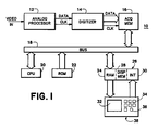
- Fig. 1 is a block diagram of an instrument using the scale to waveform locking method of the present invention.
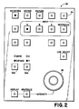
- Fig. 2 is a plan view of a front panel for the instrument of Fig. 1.
- Fig. 3 is a plan view of a waveform display having scales computed according to the present invention.
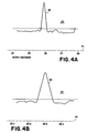
- Figs. 4A and 4B are plan views of a partial waveform display illustrating the operation of the present invention in the horizontal direction.
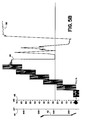
- Figs. 5A and 5B are plan views of a partial waveform display illustrating the operation of the present invention in the vertical direction.
- an instrument 10 having a video input signal, such as a television video signal.
- the video signal is conventionally processed in the analog domain by an analog processor 12, digitized by a digitizer 14, and stored in an acquisition memory 16.
- the acquisition memory 16 is connected to a communications bus 18 to which also are connected a central processing unit (CPU) 20 with associated ROM 22 and RAM 24, and a display interface unit 26.
- the display interface unit 26 includes the RAM 24, a display memory 28 and an interface circuit 30. The contents of the display memory 28 are displayed on a screen 32.
- the digitized video data from the acquisition memory 16 is processed by the CPU 20 according to the functions and parameters input by an operator via function buttons 34 and a rotary encoder knob 36 on a front panel 38, and via interaction with the screen 32.
- the processed data is stored in the display memory 28 together with appropriate scales, cursors and display information. Movement of the waveform display is affected by rotation of the rotary encoder 36, with the axis of movement determined by an X/Y button 34a. Likewise expansion of the waveform display either horizontally or vertically is affected by activation of an EXPAND/MOVE button 34b in conjunction with the selection of the X/Y button 34a while rotating the rotary encoder 36.
- Fig. 3 illustrates the initial formation by the CPU 20 of the axis scales from information provided by absolute reference points on a waveform 40 displayed.
- the time scale along the horizontal axis obtains a zero value from the occurrence of the first horizontal sync pulse 42 that appears on the screen 32, or from the immediately prior sync pulse when no sync pulse appears on the screen 32. Since the horizontal sync pulse 42 in a television video signal occurs at a regular interval, the period is a known nominal parameter and can be more precisely determined by averaging over several horizontal line intervals. With a given starting point and the known interval between sync pulses the scale markers 44 are generated plus and minus from the zero point and loaded into the display memory 28.
- a volt scale 46 provides an absolute magnitude for the waveform 40 and is taken directly from the digitized data stored in the acquisition memory 16. By taking the voltage values from two different data points on the waveform 40 the voltage scale 46 is readily computed.
- an IRE scale 48 is provided. The IRE scale 48 represents a proportional relationship contained within the waveform itself and changes with the input video signal. Initially a zero carrier pulse (ZCP) signal, or one hundred forty IRE bar, is searched for on a specified horizontal line within a frame. If the ZCP signal is found, then the zero and 140 IRE values are determined and the IRE scale 48 is computed by the CPU 20 accordingly.
- ZCP zero carrier pulse
- an NTC-7 or FCC VITS bar 50 is searched for, which defines one hundred IRE.
- one hundred forty IRE is set arbitrarily at one volt.
- Zero IRE always is set at the horizontal sync back porch.
- the amplitude of the horizontal sync pulse 42 which is nominally forty IRE, may be used to generate reference points from which the IRE scale 48 may be calculated.
- the available vertical area may vary depending upon the amount of additional information to be displayed under the waveform display.
- the CPU 20 takes into account the height of the available vertical area as well as the gain in computing the vertical labels and tick marks. For example as shown in Fig. 4A the labels are marked at one micro-second intervals, but when expanded as in Fig. 4B the labels are marked at 0.5 micro-second intervals. Likewise, as shown in Figs. 5A and 5B the volt scale labels are marked at two hundred millivolt intervals and then at one hundred millivolt intervals, while the IRE scale labels change from ten IRE unit intervals to five IRE unit intervals.
- the CPU 20 keeps track of the field/line numbers in a television video signal and labels each displayed waveform with the appropriate field/line number label 52.
- the label 52 is inserted just to the right of the left side scales 46, 48 and above the horizontal scale 44, or right after each displayed horizontal sync pulse and below the zero, or "black", level so as not to interfere with the displayed waveform.
- the present invention provides a method for locking scales to waveform displays by referencing absolute points on the waveform to determine the initial scale, and then applying the same gain factor to the scales as is applied to the waveform when the waveform is expanded. Also the field/line numbers for a television video signal are displayed for the waveform being displayed.
Landscapes
- Engineering & Computer Science (AREA)
- Physics & Mathematics (AREA)
- General Physics & Mathematics (AREA)
- Health & Medical Sciences (AREA)
- Biomedical Technology (AREA)
- General Health & Medical Sciences (AREA)
- Multimedia (AREA)
- Signal Processing (AREA)
- Testing, Inspecting, Measuring Of Stereoscopic Televisions And Televisions (AREA)
- Controls And Circuits For Display Device (AREA)
- Analysing Materials By The Use Of Radiation (AREA)
Claims (5)
- Méthode d'accrochage d'une échelle affichée à une forme d'onde affichée d'un signal normalisé, comprenant les étapes de :(a) détermination de points de référence absolue de particularités répétitives de ladite forme d'onde de signal ;(b) génération d'une échelle d'axe initiale, à partir desdits points de référence absolue ;(c) affichage d'au moins une partie de ladite forme d'onde de signal et de ladite échelle d'axe initiale; et(d) application d'un facteur de gain, choisi dans une plage de facteurs de gain, pour dilater sélectivement ledit affichage de ladite forme d'onde de signal normalisé, d'une quantité désirée, et pour modifier la dite échelle d'axe initiale par ledit facteur de gain, afin de produire une échelle d'axe modifiée ;de sorte que le calibrage est conservé entre ladite échelle d'axe affichée et la forme d'onde affichée, lorsque ladite forme d'onde affichée est dilatée.
- Méthode suivant la revendication 1, dans laquelle la forme d'onde affichée (40) est la forme d'onde d'un signal vidéo et l'étape de détermination comprend :
l'identification de points de synchronisation horizontale (42) de ladite forme d'onde, le long de l'axe horizontal, et
l'identification de niveaux prédéterminés (50) de ladite forme d'onde, le long de l'axe vertical. - Méthode suivant la revendication 2, dans laquelle l'étape de génération comprend :
le calcul d'une échelle de temps (44) pour l'axe horizontal, à partir de la distance entre les points de synchronisation horizontale (42),
le calcul d'une échelle verticale (46,48) à partir desdits niveaux prédéterminés (50), et
la numérotation des divisions des échelles affichées,en fonction du facteur de gain appliqué aux échelles. - Méthode suivant la revendication 2 ou la revendication 3, dans laquelle une échelle de tension (46) ou une échelle IRE (48) est affichée le long de l'axe vertical.
- Affichage de forme d'onde comprenant :
une entrée pour un signal normalisé ;
des moyens de traitement (20) pour déterminer des points de référence absolue de particularités répétitives dudit signal ;
des moyens de génération d'échelle initiale pour engendrer une échelle d'axe initiale à partir desdits points de référence absolue ;
des moyens d'affichage pour la forme d'onde du dit signal normalisé et une échelle d'axe ;
des moyens de commande pour appliquer un facteur de gain, choisi dans une plage continuellement variable de facteurs de gain, afin d'agrandir sélectivement ledit affichage de ladite forme d'onde ;
des moyens de modification d'échelle d'axe initiale, pour appliquer le facteur de gain à ladite échelle d'axe, ce facteur de gain étant fonction dudit facteur de gain ;
de sorte que le calibrage est conservé entre une échelle d'axe affichée sur lesdits moyens d'affichage et ladite forme d'onde affichée, lorsque ladite forme d'onde affichée est agrandie.
Applications Claiming Priority (2)
| Application Number | Priority Date | Filing Date | Title |
|---|---|---|---|
| US30760 | 1987-03-24 | ||
| US07/030,760 US4764721A (en) | 1987-03-24 | 1987-03-24 | Locking scales to waveform displays |
Publications (2)
| Publication Number | Publication Date |
|---|---|
| EP0284078A1 EP0284078A1 (fr) | 1988-09-28 |
| EP0284078B1 true EP0284078B1 (fr) | 1993-10-13 |
Family
ID=21855882
Family Applications (1)
| Application Number | Title | Priority Date | Filing Date |
|---|---|---|---|
| EP88104773A Expired - Lifetime EP0284078B1 (fr) | 1987-03-24 | 1988-03-24 | Verrouillage d'échelles pour affichage d'onde |
Country Status (6)
| Country | Link |
|---|---|
| US (1) | US4764721A (fr) |
| EP (1) | EP0284078B1 (fr) |
| JP (1) | JPH07104363B2 (fr) |
| CA (1) | CA1301970C (fr) |
| DE (1) | DE3884834T2 (fr) |
| DK (1) | DK157888A (fr) |
Families Citing this family (7)
| Publication number | Priority date | Publication date | Assignee | Title |
|---|---|---|---|---|
| US5440676A (en) * | 1988-01-29 | 1995-08-08 | Tektronix, Inc. | Raster scan waveform display rasterizer with pixel intensity gradation |
| US5004975A (en) * | 1990-06-28 | 1991-04-02 | Tektronix, Inc. | Adjustable electronic graticules for measuring waveform distortions |
| NL9001842A (nl) * | 1990-08-20 | 1992-03-16 | Philips Nv | Meetinstrument en tijdbasisschakeling geschikt voor toepassing in een dergelijk meetinstrument. |
| US5138252A (en) * | 1990-11-09 | 1992-08-11 | Hewlett-Packard Company | Automatic scaling for display of modulation domain measurements |
| WO1992017871A1 (fr) * | 1991-04-03 | 1992-10-15 | Magni Systems, Inc. | Reticule adaptatif pour un moniteur de forme d'onde a affichage par trame |
| JP2001144148A (ja) * | 2001-05-12 | 2001-05-25 | Advantest Corp | 半導体試験装置のウエハマップ表示装置 |
| JP5456581B2 (ja) * | 2010-06-01 | 2014-04-02 | 日置電機株式会社 | 測定装置および経過時間表示方法 |
Family Cites Families (9)
| Publication number | Priority date | Publication date | Assignee | Title |
|---|---|---|---|---|
| US3118085A (en) * | 1958-12-29 | 1964-01-14 | Nouvelie D Electronique Soc | Electronic marking apparatus for the generation of marker signs |
| US3204144A (en) * | 1963-02-05 | 1965-08-31 | California Instr Corp | Oscilloscope control circuitry |
| US3873918A (en) * | 1971-11-04 | 1975-03-25 | Coulter Electronics | Particle analyzing apparatus including a system for visually displaying a particle size distribution curve on a 100 percent scale irrespective of the quantity of particles sampled by the apparatus |
| JPS51817A (fr) * | 1974-06-20 | 1976-01-07 | Fujitsu Ltd | |
| US4092567A (en) * | 1976-03-17 | 1978-05-30 | Hewlett-Packard Company | Method and circuit for generating diamond markers |
| JPS5498532A (en) * | 1978-01-23 | 1979-08-03 | Toshiba Corp | Enlarged display system |
| IT1107869B (it) * | 1978-09-20 | 1985-12-02 | Olivetti & Co Spa | Dispositivo e metodo di visualizzazione di immagini per un calcolatore programmabili |
| CH633889A5 (de) * | 1978-11-24 | 1982-12-31 | Bbc Brown Boveri & Cie | Digitalvoltmeter mit elektrooptischer anzeige der wellenform. |
| US4295135A (en) * | 1978-12-18 | 1981-10-13 | Josef Sukonick | Alignable electronic background grid generation system |
-
1987
- 1987-03-24 US US07/030,760 patent/US4764721A/en not_active Expired - Lifetime
-
1988
- 1988-02-29 CA CA000560101A patent/CA1301970C/fr not_active Expired - Fee Related
- 1988-03-22 JP JP63068013A patent/JPH07104363B2/ja not_active Expired - Lifetime
- 1988-03-23 DK DK157888A patent/DK157888A/da not_active IP Right Cessation
- 1988-03-24 DE DE88104773T patent/DE3884834T2/de not_active Expired - Lifetime
- 1988-03-24 EP EP88104773A patent/EP0284078B1/fr not_active Expired - Lifetime
Also Published As
| Publication number | Publication date |
|---|---|
| JPH07104363B2 (ja) | 1995-11-13 |
| JPS63253262A (ja) | 1988-10-20 |
| DE3884834D1 (de) | 1993-11-18 |
| EP0284078A1 (fr) | 1988-09-28 |
| DE3884834T2 (de) | 1994-04-28 |
| DK157888A (da) | 1988-09-25 |
| US4764721A (en) | 1988-08-16 |
| DK157888D0 (da) | 1988-03-23 |
| CA1301970C (fr) | 1992-05-26 |
Similar Documents
| Publication | Publication Date | Title |
|---|---|---|
| US4972138A (en) | Oscilloscope-like user-interface for a logic analyzer | |
| US5758129A (en) | Data display apparatus | |
| EP0105791A1 (fr) | Générateur programmable de modèle d'essai vidéo pour des systèmes d'affichage | |
| EP0283996B1 (fr) | Interface pour curseur pour des affichages de formes d'onde | |
| JPH0782052B2 (ja) | タイミング・パルスのジッタ測定方法 | |
| EP0284078B1 (fr) | Verrouillage d'échelles pour affichage d'onde | |
| US3967266A (en) | Display apparatus having improved cursor enhancement | |
| US4761640A (en) | Positioning cursors at specific points on a waveform display | |
| JPS5852235B2 (ja) | ラスタ走査型表示装置用カ−ソル発生装置 | |
| EP0123381B1 (fr) | Appareil pour l'affichage des données logiques | |
| US4740841A (en) | Correlation of video data between two display formats | |
| US4816897A (en) | Chrominance to luminance delay and gain measurement display | |
| US5387925A (en) | Test signal generator position cursors | |
| US5166779A (en) | Subcarrier to horizontal phase measurement and display for multiple video signals | |
| EP0132925B1 (fr) | Système de diagnostic pour un dispositif d'affichage de type à balayage de trames | |
| JP2531555B2 (ja) | カ―ソル移動制御方法 | |
| NL8004331A (nl) | Methode voor het weergeven van logische signalen. | |
| JPH0749420Y2 (ja) | 遅延掃引表示回路 | |
| EP0586424B1 (fr) | Simulation video de la reponse d'un tube cathodique | |
| JPS6343684B2 (fr) | ||
| JPH06324082A (ja) | デジタル・ストレージ・オシロスコープ | |
| JPS6021396B2 (ja) | クロスヘアカ−ソル発生装置 | |
| JPS6352387B2 (fr) | ||
| JPH0989607A (ja) | 測定器用測定期間信号発生器 | |
| JPH0760162B2 (ja) | 波形表示装置 |
Legal Events
| Date | Code | Title | Description |
|---|---|---|---|
| PUAI | Public reference made under article 153(3) epc to a published international application that has entered the european phase |
Free format text: ORIGINAL CODE: 0009012 |
|
| AK | Designated contracting states |
Kind code of ref document: A1 Designated state(s): DE FR GB NL |
|
| 17P | Request for examination filed |
Effective date: 19881122 |
|
| 17Q | First examination report despatched |
Effective date: 19910521 |
|
| GRAA | (expected) grant |
Free format text: ORIGINAL CODE: 0009210 |
|
| AK | Designated contracting states |
Kind code of ref document: B1 Designated state(s): DE FR GB NL |
|
| PG25 | Lapsed in a contracting state [announced via postgrant information from national office to epo] |
Ref country code: FR Effective date: 19931013 Ref country code: NL Effective date: 19931013 |
|
| REF | Corresponds to: |
Ref document number: 3884834 Country of ref document: DE Date of ref document: 19931118 |
|
| EN | Fr: translation not filed | ||
| NLV1 | Nl: lapsed or annulled due to failure to fulfill the requirements of art. 29p and 29m of the patents act | ||
| PLBE | No opposition filed within time limit |
Free format text: ORIGINAL CODE: 0009261 |
|
| STAA | Information on the status of an ep patent application or granted ep patent |
Free format text: STATUS: NO OPPOSITION FILED WITHIN TIME LIMIT |
|
| 26N | No opposition filed | ||
| REG | Reference to a national code |
Ref country code: GB Ref legal event code: IF02 |
|
| PGFP | Annual fee paid to national office [announced via postgrant information from national office to epo] |
Ref country code: GB Payment date: 20070214 Year of fee payment: 20 |
|
| PGFP | Annual fee paid to national office [announced via postgrant information from national office to epo] |
Ref country code: DE Payment date: 20070226 Year of fee payment: 20 |
|
| PG25 | Lapsed in a contracting state [announced via postgrant information from national office to epo] |
Ref country code: GB Free format text: LAPSE BECAUSE OF EXPIRATION OF PROTECTION Effective date: 20080323 |