EP0284332A2 - Spectromètre de masse quadripolaire à temps de vol focalisant - Google Patents
Spectromètre de masse quadripolaire à temps de vol focalisant Download PDFInfo
- Publication number
- EP0284332A2 EP0284332A2 EP88302470A EP88302470A EP0284332A2 EP 0284332 A2 EP0284332 A2 EP 0284332A2 EP 88302470 A EP88302470 A EP 88302470A EP 88302470 A EP88302470 A EP 88302470A EP 0284332 A2 EP0284332 A2 EP 0284332A2
- Authority
- EP
- European Patent Office
- Prior art keywords
- ion
- focusing
- ions
- flight
- mass spectrometer
- Prior art date
- Legal status (The legal status is an assumption and is not a legal conclusion. Google has not performed a legal analysis and makes no representation as to the accuracy of the status listed.)
- Withdrawn
Links
- 150000002500 ions Chemical class 0.000 claims abstract description 170
- 238000010276 construction Methods 0.000 description 7
- 238000004949 mass spectrometry Methods 0.000 description 5
- 238000001514 detection method Methods 0.000 description 4
- 239000002245 particle Substances 0.000 description 4
- 239000000523 sample Substances 0.000 description 4
- 238000010586 diagram Methods 0.000 description 3
- 238000005259 measurement Methods 0.000 description 3
- 238000000034 method Methods 0.000 description 3
- 238000001228 spectrum Methods 0.000 description 3
- 230000001133 acceleration Effects 0.000 description 2
- 238000007596 consolidation process Methods 0.000 description 2
- 230000005684 electric field Effects 0.000 description 2
- 238000001819 mass spectrum Methods 0.000 description 2
- 239000000463 material Substances 0.000 description 2
- 238000001269 time-of-flight mass spectrometry Methods 0.000 description 2
- 208000036366 Sensation of pressure Diseases 0.000 description 1
- 238000004458 analytical method Methods 0.000 description 1
- 150000001450 anions Chemical class 0.000 description 1
- 239000011324 bead Substances 0.000 description 1
- 150000001768 cations Chemical class 0.000 description 1
- 150000001793 charged compounds Chemical class 0.000 description 1
- 238000006073 displacement reaction Methods 0.000 description 1
- 238000009826 distribution Methods 0.000 description 1
- 230000000694 effects Effects 0.000 description 1
- 230000005670 electromagnetic radiation Effects 0.000 description 1
- 210000003414 extremity Anatomy 0.000 description 1
- 239000012634 fragment Substances 0.000 description 1
- 238000007689 inspection Methods 0.000 description 1
- 230000005596 ionic collisions Effects 0.000 description 1
- 210000003141 lower extremity Anatomy 0.000 description 1
- 238000005036 potential barrier Methods 0.000 description 1
- 230000002265 prevention Effects 0.000 description 1
- 230000001846 repelling effect Effects 0.000 description 1
- 210000001364 upper extremity Anatomy 0.000 description 1
Images
Classifications
-
- H—ELECTRICITY
- H01—ELECTRIC ELEMENTS
- H01J—ELECTRIC DISCHARGE TUBES OR DISCHARGE LAMPS
- H01J49/00—Particle spectrometers or separator tubes
- H01J49/26—Mass spectrometers or separator tubes
- H01J49/34—Dynamic spectrometers
- H01J49/40—Time-of-flight spectrometers
- H01J49/408—Time-of-flight spectrometers with multiple changes of direction, e.g. by using electric or magnetic sectors, closed-loop time-of-flight
Definitions
- This invention relates to time of flight mass spectrometers. It relates more particularly to quadruple focusing time of flight mass spectrometers.
- Time of flight (TOF) mass spectrometers have developed into well established analytical instruments for identifying materials based on a distribution (spectrum) of charged particles differing in mass created by pulsed radiant energy or particle bombardment.
- a sample of material whose spectrum is sought is mounted as a target in an electric field. Bombardment with accelerated particles, such as perfect gas atoms or ions, or high intensity electromagnetic radiation, disrupts the molecules of the target to create a variety of charged particles-e.g., molecular ions, fragments, cations, and/or anions-hereinafter collectively referred to as ions.
- Once an ion of the sample material is created it is accelerated in the electric field toward an electrode of opposite charge. A portion of accelerated ions is allowed to pass through an aperture in the attracting electrode and embark on a flight path which, through creation of an ambient vacuum, can be of extended length.
- the solution to this problem has been to provide a focusing deflection field in the flight path.
- the deflection field causes the partial parcels to traverse one or more arcs.
- the ions of higher kinetic energies in undergoing the same angular deflection traverse arcs of longer radii than ions of lower kinetic energies.
- the time required for ions of differing kinetic energies within each partial parcel to traverse the deflection field is evened out by the unequal arc paths.
- the function of the deflection field is to make the flight time of ions in each partial parcel a function of the ratio of ion mass (m) to charge (e) rather than initial differences in kinetic energies.
- quadruple focusing four deflection arcs are required to bring the partial parcels of ions exiting the deflection field into focus spatially (as measured along the three mutually perpendicular axes of space, usually referred to as X, Y, and Z axes), as well as in terms of elapsed time of flight (t), momentum (mv), and kinetic energy (0.5mv2).
- t time of flight
- mv momentum
- kinetic energy 0.5mv2
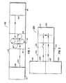
- FIG. 1 A schematic diagram of a conventional quadruple focusing time of flight (QFTOF) mass spectrometer containing a deflection field is shown in Figure 1.
- the mass spectrometer 100 is comprised of a central vacuum chamber 102 defining an ion flight path indicated by arrows 104 extending between an entrance plane 106 and an exit plane 108.
- the ambient pressure in the vacuum chamber is maintained below 1.33 X 10 ⁇ 6 kilopascals ( ⁇ 10 ⁇ 5 torr) to minimize ion collisions with the ambient atmosphere.
- a pulsed ion source 116 emits a parcel of accelerated ions across the entrance plane into the flight path within the vacuum chamber.
- the ion source is also internally evacuated and can therefore be viewed as an extension of the flight path vacuum chamber.
- a receiving unit 118 for the ions traveling along the flight path is located beyond the exit plane.
- the receiving unit forms a second extension of the ion flight path vacuum chamber.
- the conventional QFTOF spectrometer shown in Figure 1 focuses the partial parcels of ions by directing the flight path through the four separate deflection arcs which are arranged to be symmetrical about a central point S in the flight path.
- Each of the deflection arcs lies in a common central reference plane with limited divergence of ions from the central reference plane being permitted.
- QFTOF mass spectrometers are similar to progenitor TOF mass spectrometers lacking focusing deflection fields.
- It is an object of this invention to provide a quadruple focusing time of flight mass spectrometer comprised of (i) means including an entrance plane and an exit plane defining an ion flight path in which parcels of ions divide into partial parcels of equal effective mass, (ii) a pulsed ion source which emits a parcel of accelerated ions across the entrance plane into the flight path, and (iii) means for detecting the partial parcels of ions beyond the exit plane and recording their elapsed time of flight between the entrance and exit planes, the flight path defining means including a deflection zone comprised of first, second, third, and fourth separate focusing means for each in sequence guiding the ions through first, second, third, and fourth deflection arcs, respectively, with limited divergence from a central reference plane, wherein ions enter and exit from the deflection zone traveling in opposite directions.
- the object of the invention is realized by a quadruple focusing time of flight mass spectrometer as described above characterized in that the second and third focusing means share a common central reference plane which is perpendicular to central reference planes of the first and fourth focusing means and the first and second focusing means define a first segment of the ion flight path in the deflection zone which is a mirror image of a second segment of the ion flight path formed by the third and fourth focusing means.
- the QFTOF mass spectrometers of the present invention provide for the first time a QFTOF mass spectrometer construction in which the ion source and detection units can be proximally located if not at least partially integrated. This permits simplification and consolidation of structure. It also is a convenience in initial adjustment and in operation. For example, one operator can simultaneously inspect both the ion source and detection portions of the apparatus. Further, the construction of the vacuum chamber defining the flight path can be highly simplified. The vacuum chamber can be constructed with one closed end so that only one vacuum seal is necessary. Additionally, the length of the flight path in the vacuum chamber can be greatly elongated without complicating adjustment or operation of the apparatus.
- a QFTOF mass spectrometer 200 is shown in Figure 2.
- a pulsed ion source 201 and anion detection unit 203 are located in proximity.
- a vacuum chamber 205 having a closed end 207 is in sealed contact with the source and detection units.
- An ion flight path L lies within the vacuum chamber extending from an entrance plane 209 through a predeflection flight path zone 211, a deflection zone 213, and a return flight path zone 215 to an exit plane 217.
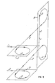
- the flight path of the ions in the deflection zone is best appreciated by reference to Figure 3.
- the focusing units themselves are omitted from Figure 3 so that the deflection arcs and central reference planes of the focusing units can be better viewed.
- a central reference plane P1 of the first focusing unit receives ions traveling along incoming ion flight path L1, deflects the ions through an arc A1 lying in the reference plane, and directs the ions along a second flight path L2 to the second focusing unit.
- the second focusing unit receives the ions on the flight path L2 in a central reference plane P2, deflects the ions through an arc A2 lying in the second reference plane, and directs the ions along a third flight path L3 to a third focusing unit.
- the third focusing unit is oriented to have a central reference plane common to the second focusing unit-i.e., the second and third focusing units share reference plane P2.
- the third focusing unit receives ions following flight path L3, deflects the ions through an arc A3, and directs the ions to the fourth focusing unit along flight path L4.
- the fourth focusing unit receives the ions following flight path L4 in central reference plane P3, deflects the ions through an arc A4 and directs the ions toward the exit plane along flight path L5. While deviation of the flight paths of individual ions above and below the central reference planes occurs, these deviations are small.
- This advantageous effect is achieved orienting the focusing units so that said first and second focusing units define a first segment of the ion flight path in said deflection zone which is a mirror image of a second segment of the ion flight path formed by said third and fourth focusing units, the flight path in the deflection zone can be viewed as two symmetrical segments, one segment extending from the point of entry of the ions into the deflection zone to the point S' and the second segment extending from the point S' to point of exit of the ions from the deflection zone. In addition to being symmetrical the two segments are mirror images.
- the first and second focusing units generate ion flight paths (including deflection arcs) which are mirror images of those generated by the fourth and third focusing units, respectively.
- the symmetry of the mirror image flight path segments refers, of course, to their geometrical configuration only, since individual ions progress from one flight path segment to the next.
- An important contribution to achieving this symmetrical relationship is the orientation of the first and fourth focusing units in separate reference planes with these reference planes perpendicularly intersecting the reference common reference plane of the second and third focusing units.
- the orientation of the focusing units in three separate reference planes is, of course, a significant departure from the prior state of the art, wherein all four focusing units are mounted in a common reference plane.
- each of the arcs A1, A2, A3, and A4 are equal. From mathematical analysis it is known that four identical 269° deflection arcs are ideal for QFTOF mass spectometers. In practice deflection angles of approximately 269° (269° ⁇ 2°) are common in QFTOF mass spectometers. It is to be noted that the lines of flight L1 and L5 are parallel when each of the deflection arcs A1, A2, A3, and A4 are equal, regardless of the specific angle chosen. For example, parallel incoming and exit lines of flight are possible with ideal deflection arcs of exactly 269°C as well as with deflection arcs of only approximately 269°.
- the individual focusing units can be of any convenient conventional construction.
- a pair of focusing electrodes are constructed of an inner electrode presenting an inner ion guiding surface and an outer electrode providing a spaced outer ion guiding surface.
- the two ion guiding surfaces are cylindrical over the desired deflection arc.
- ions traveling along a linear flight path enter the space between the inner and outer electrodes.
- the ions in the flight path all exhibit the same charge polarity. In addition they exhibit a range of kinetic energies above and below an average value.
- the inner and outer electrodes are electrically biased to exhibit the same polarity as the ions.
- the voltage applied to the outer electrode is higher than that applied to the inner electrode.
- the voltages can be selected by known relationships to allow ions of average kinetic energy to traverse the arc defined by the spaced electrodes along a flight path mid-way between the opposed inner and outer ion guiding surfaces.
- the ions are deflected and guided by charge repulsion. Ions of slightly higher than average kinetic energies must approach the outer ion guiding surface somewhat more closely to be repelled and therefore traverse an arc of a slightly longer than average radius. Conversely, ions of slightly lower than average kinetic energies are repelled from the outer electrode ion guiding surface more readily and traverse an arc having a somewhat shorter than average radius. This contributes to focusing partial parcels of ions, as described above.
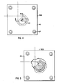
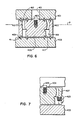
- FIGs 4 to 7 inclusive illustrate a preferred focusing unit 400.
- the electrodes are electrically isolated from the mounting plates by being supported on insulative beads 409 seated in aligned recesses 411 in the mounting plates and electrodes.
- the inner and outer electrodes provide inner and outer ion guiding surfaces 413 and 415, respectively, symmetrically traversing a central reference plane P.
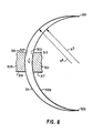
- the inner and outer ion guiding surfaces converge toward their upper and lower edges and, conversely, are most widely spaced in the reference plane (refer to Figure 8 below).
- the inner electrode Below its ion guiding surface the inner electrode is provided with a mounting spindle 417 which can be of any convenient shape.
- the outer electrode below its ion guiding surface is internally recessed at 419 to increase its spacing from the inner electrode.
- the upper mounting plate 401 is provided with a slot 421 over the inner electrode to permit access to a lead attachment screw 423 threaded into the inner electrode.
- a lead mounting screw 425 is threaded into the outer electrode.
- Bolts 427 are employed to compress the mounting plates against the electrodes, thereby holding the electrodes in their desired spatial arrangement.
- the portions of the inner and outer electrodes below their ion guiding surfaces are mere conveniences of construction and are not required. If desired, the ion guiding surfaces can extend from the top to the bottom of both the inner and outer electrodes.
- the mounting plates in the preferred deflection field unit are grounded.
- the mounting plates, being electrically isolated from both electrodes can, if desired, be biased to serve as conventional field plates, but this is not required, since the curvature of the ion guiding surfaces can be entirely relied upon to prevent ion escape from the deflection fields.
- the use of mounting plates to locate the electrodes in position is not required, since the availability of alternative mounting arrangements can be readily appreciated.
- a significant advantage of the focusing unit 400 for conventional focusing units is attributed to the inner and outer electrodes having spaced opposed ion guiding surfaces which are curved in planes normal to the ion flight path.
- the inner electrode presents an ion guiding surface which is convex in planes normal to the ion flight path while the outer electrode presents an ion guiding surface which is concave in planes normal to the ion flight path.
- the inner and outer electrode ion guiding surfaces are more closely spaced at their edges than mediate their edges.
- Inner electrode 301 is shown providing an inner ion guiding surface 303 while spaced outer electrode 305 is shown providing an outer ion guiding surface 307.
- the inner ion guiding surface is defined by the perimeter of a sphere 309 partially shown in section having a radius R3.
- the outer ion guiding surface of the outer electrode is defined by the perimeter of an ellipsoid in this instance as oblate sphere 311 partially shown in section.
- the minor radius of curvature R4 of the ellipsoid or oblate sphere is equal to the radius of curvature of the sphere.
- the opposed upper edges 313 and 315 of the inner and outer electrodes as well as the opposed lower edges 317 and 319 of the these electrodes are closer together than other portions of the inner and outer ion guiding surfaces. This can be visually confirmed merely be noting that the surfaces of the sphere and oblate sphere merge at their upper extremity 321, diverge smoothly until reaching the level of the ideal ion flight path L equally spaced from the upper and lower edges of the inner and outer electrodes, and then converge smoothly toward their common lower extremity 323.
- inner ion guiding surface has a radius of curvature R3 which is equal to the radius of curvature R4 of the outer ion guiding surface.
- the desired reduced edge spacing of the ion guiding surfaces can be realized so long as the radius of curvature R3 is equal to or greater than the radius of curvature R4.
- the inner ion guiding surface conforms to the periphery of a sphere while the outer ion guiding surface conforms to the periphery of an oblate sphere, where R4 is the minor radius of the oblate sphere.
- outer ion guiding surface is a spherical section with the inner ion guiding surface being formed by the major radius of an ellipsoid.
- inner ion guiding surface is formed by the major radius of an ellipsoid.
- neither spherical nor ellipsoidal surface geometries are required. So long as the edge spacing relationship is satisfied any other convenient curved ion guiding surface configuration can be employed. For example, such surface can be generated by the rotation of a parabola, catenary, or other conveniently mathematically generated curve about an axis.
Landscapes
- Chemical & Material Sciences (AREA)
- Analytical Chemistry (AREA)
- Other Investigation Or Analysis Of Materials By Electrical Means (AREA)
Applications Claiming Priority (2)
| Application Number | Priority Date | Filing Date | Title |
|---|---|---|---|
| US31340 | 1987-03-27 | ||
| US07/031,340 US4754135A (en) | 1987-03-27 | 1987-03-27 | Quadruple focusing time of flight mass spectrometer |
Publications (1)
| Publication Number | Publication Date |
|---|---|
| EP0284332A2 true EP0284332A2 (fr) | 1988-09-28 |
Family
ID=21858891
Family Applications (1)
| Application Number | Title | Priority Date | Filing Date |
|---|---|---|---|
| EP88302470A Withdrawn EP0284332A2 (fr) | 1987-03-27 | 1988-03-22 | Spectromètre de masse quadripolaire à temps de vol focalisant |
Country Status (2)
| Country | Link |
|---|---|
| US (1) | US4754135A (fr) |
| EP (1) | EP0284332A2 (fr) |
Families Citing this family (10)
| Publication number | Priority date | Publication date | Assignee | Title |
|---|---|---|---|---|
| US4988628A (en) * | 1989-02-28 | 1991-01-29 | New England Deaconess Hospital Corporation | Method of drug detection |
| US5128543A (en) * | 1989-10-23 | 1992-07-07 | Charles Evans & Associates | Particle analyzer apparatus and method |
| US5013923A (en) * | 1990-03-01 | 1991-05-07 | University Of Toronto Innovations Foundation | Mass recombinator for accelerator mass spectrometry |
| US5180914A (en) * | 1990-05-11 | 1993-01-19 | Kratos Analytical Limited | Mass spectrometry systems |
| US5534699A (en) * | 1995-07-26 | 1996-07-09 | National Electrostatics Corp. | Device for separating and recombining charged particle beams |
| JPH11135060A (ja) * | 1997-10-31 | 1999-05-21 | Jeol Ltd | 飛行時間型質量分析計 |
| US6037586A (en) * | 1998-06-18 | 2000-03-14 | Universite Laval | Apparatus and method for separating pulsed ions by mass as said pulsed ions are guided along a course |
| WO2000017909A1 (fr) * | 1998-09-23 | 2000-03-30 | Varian Australia Pty Ltd | Systeme optique ionique pour spectrometre de masse |
| US6867414B2 (en) * | 2002-09-24 | 2005-03-15 | Ciphergen Biosystems, Inc. | Electric sector time-of-flight mass spectrometer with adjustable ion optical elements |
| US8026480B2 (en) * | 2007-05-22 | 2011-09-27 | Shimadzu Corporation | Mass spectrometer |
Family Cites Families (1)
| Publication number | Priority date | Publication date | Assignee | Title |
|---|---|---|---|---|
| US3863068A (en) * | 1972-07-27 | 1975-01-28 | Max Planck Gesellschaft | Time-of-flight mass spectrometer |
-
1987
- 1987-03-27 US US07/031,340 patent/US4754135A/en not_active Expired - Fee Related
-
1988
- 1988-03-22 EP EP88302470A patent/EP0284332A2/fr not_active Withdrawn
Also Published As
| Publication number | Publication date |
|---|---|
| US4754135A (en) | 1988-06-28 |
Similar Documents
| Publication | Publication Date | Title |
|---|---|---|
| US6727495B2 (en) | Ion mobility spectrometer with high ion transmission efficiency | |
| EP3891777B1 (fr) | Appareil d'analyse simultanée de multiples ions avec un piège à ions linéaire électrostatique | |
| JP3713557B2 (ja) | 小型質量フィルタ | |
| US6661001B2 (en) | Extended bradbury-nielson gate | |
| USRE42111E1 (en) | Multideflector | |
| JPH07508127A (ja) | 低速単色性電子を用いた質量分析方法及び装置 | |
| US20130240725A1 (en) | Method of Mass Selecting Ions and Mass Selector | |
| US6521887B1 (en) | Time-of-flight ion mass spectrograph | |
| EP0284332A2 (fr) | Spectromètre de masse quadripolaire à temps de vol focalisant | |
| US9401268B2 (en) | Mass spectrometer with optimized magnetic shunt | |
| US7186972B2 (en) | Time of flight mass analyzer having improved mass resolution and method of operating same | |
| CN1816383A (zh) | 质谱仪和相关的离子发生器及方法 | |
| US4774408A (en) | Time of flight mass spectrometer | |
| JPH0352180B2 (fr) | ||
| EP2943971B1 (fr) | Spectromètre de masse à secteur magnétique perfectionné | |
| EP0456516B1 (fr) | Dispositif de regroupement de paquets d'ions | |
| US6791077B1 (en) | Mass analyzer allowing parallel processing one or more analytes | |
| US7439520B2 (en) | Ion optics systems | |
| Tabrizchi et al. | Design, construction and calibration of a laser ionization time-of-flight mass spectrometer | |
| US3925662A (en) | High-resolution focussing dipole mass spectrometer | |
| JP2023549626A (ja) | 質量分析計および方法 | |
| Ledford Jr et al. | Mass measurement accuracy of a trapped ion cyclotron resonance mass spectrometer | |
| US2958774A (en) | Omegatron with orbit increment detection | |
| Poschenrieder et al. | New Directional and Energy Focusing Time of Flight Mass Spectrometers for Special Tasks in Vacuum and Surface Physics | |
| Spengler | New instrumental approaches to collision-induced dissociation using a time-of-flight instrument |
Legal Events
| Date | Code | Title | Description |
|---|---|---|---|
| PUAI | Public reference made under article 153(3) epc to a published international application that has entered the european phase |
Free format text: ORIGINAL CODE: 0009012 |
|
| AK | Designated contracting states |
Kind code of ref document: A2 Designated state(s): DE FR GB |
|
| STAA | Information on the status of an ep patent application or granted ep patent |
Free format text: STATUS: THE APPLICATION HAS BEEN WITHDRAWN |
|
| 18W | Application withdrawn |
Withdrawal date: 19890606 |
|
| R18W | Application withdrawn (corrected) |
Effective date: 19890606 |